EP0721043B1 - Dispositif de surveillance pour un câble porteur d'un panneau de porte - Google Patents
Dispositif de surveillance pour un câble porteur d'un panneau de porte Download PDFInfo
- Publication number
- EP0721043B1 EP0721043B1 EP96100122A EP96100122A EP0721043B1 EP 0721043 B1 EP0721043 B1 EP 0721043B1 EP 96100122 A EP96100122 A EP 96100122A EP 96100122 A EP96100122 A EP 96100122A EP 0721043 B1 EP0721043 B1 EP 0721043B1
- Authority
- EP
- European Patent Office
- Prior art keywords
- catching
- door leaf
- cable
- eccentric
- mechanical
- Prior art date
- Legal status (The legal status is an assumption and is not a legal conclusion. Google has not performed a legal analysis and makes no representation as to the accuracy of the status listed.)
- Expired - Lifetime
Links
- 238000012806 monitoring device Methods 0.000 title description 16
- 230000000903 blocking effect Effects 0.000 claims description 19
- 229910000831 Steel Inorganic materials 0.000 claims description 4
- 239000010959 steel Substances 0.000 claims description 4
- 230000009471 action Effects 0.000 claims description 3
- 230000006835 compression Effects 0.000 claims description 2
- 238000007906 compression Methods 0.000 claims description 2
- 238000012544 monitoring process Methods 0.000 claims 10
- 230000002093 peripheral effect Effects 0.000 claims 1
- 239000000725 suspension Substances 0.000 description 33
- 230000001960 triggered effect Effects 0.000 description 8
- 230000015572 biosynthetic process Effects 0.000 description 2
- 238000000034 method Methods 0.000 description 2
- 230000008569 process Effects 0.000 description 2
- 238000012546 transfer Methods 0.000 description 2
- 238000004804 winding Methods 0.000 description 2
- 230000002411 adverse Effects 0.000 description 1
- 230000005540 biological transmission Effects 0.000 description 1
- 238000013461 design Methods 0.000 description 1
- 230000000694 effects Effects 0.000 description 1
- 238000012986 modification Methods 0.000 description 1
- 230000004048 modification Effects 0.000 description 1
- 230000035515 penetration Effects 0.000 description 1
- 230000002040 relaxant effect Effects 0.000 description 1
- 230000001360 synchronised effect Effects 0.000 description 1
- 238000012549 training Methods 0.000 description 1
Images



Classifications
-
- E—FIXED CONSTRUCTIONS
- E05—LOCKS; KEYS; WINDOW OR DOOR FITTINGS; SAFES
- E05D—HINGES OR SUSPENSION DEVICES FOR DOORS, WINDOWS OR WINGS
- E05D13/00—Accessories for sliding or lifting wings, e.g. pulleys, safety catches
- E05D13/003—Anti-dropping devices
- E05D13/006—Anti-dropping devices fixed to the wing, i.e. safety catches
-
- E—FIXED CONSTRUCTIONS
- E05—LOCKS; KEYS; WINDOW OR DOOR FITTINGS; SAFES
- E05Y—INDEXING SCHEME ASSOCIATED WITH SUBCLASSES E05D AND E05F, RELATING TO CONSTRUCTION ELEMENTS, ELECTRIC CONTROL, POWER SUPPLY, POWER SIGNAL OR TRANSMISSION, USER INTERFACES, MOUNTING OR COUPLING, DETAILS, ACCESSORIES, AUXILIARY OPERATIONS NOT OTHERWISE PROVIDED FOR, APPLICATION THEREOF
- E05Y2201/00—Constructional elements; Accessories therefor
- E05Y2201/60—Suspension or transmission members; Accessories therefor
- E05Y2201/622—Suspension or transmission members elements
- E05Y2201/644—Flexible elongated pulling elements
- E05Y2201/654—Cables
-
- E—FIXED CONSTRUCTIONS
- E05—LOCKS; KEYS; WINDOW OR DOOR FITTINGS; SAFES
- E05Y—INDEXING SCHEME ASSOCIATED WITH SUBCLASSES E05D AND E05F, RELATING TO CONSTRUCTION ELEMENTS, ELECTRIC CONTROL, POWER SUPPLY, POWER SIGNAL OR TRANSMISSION, USER INTERFACES, MOUNTING OR COUPLING, DETAILS, ACCESSORIES, AUXILIARY OPERATIONS NOT OTHERWISE PROVIDED FOR, APPLICATION THEREOF
- E05Y2201/00—Constructional elements; Accessories therefor
- E05Y2201/60—Suspension or transmission members; Accessories therefor
- E05Y2201/622—Suspension or transmission members elements
- E05Y2201/658—Members cooperating with flexible elongated pulling elements
- E05Y2201/66—Deflectors; Guides
-
- E—FIXED CONSTRUCTIONS
- E05—LOCKS; KEYS; WINDOW OR DOOR FITTINGS; SAFES
- E05Y—INDEXING SCHEME ASSOCIATED WITH SUBCLASSES E05D AND E05F, RELATING TO CONSTRUCTION ELEMENTS, ELECTRIC CONTROL, POWER SUPPLY, POWER SIGNAL OR TRANSMISSION, USER INTERFACES, MOUNTING OR COUPLING, DETAILS, ACCESSORIES, AUXILIARY OPERATIONS NOT OTHERWISE PROVIDED FOR, APPLICATION THEREOF
- E05Y2900/00—Application of doors, windows, wings or fittings thereof
- E05Y2900/10—Application of doors, windows, wings or fittings thereof for buildings or parts thereof
- E05Y2900/106—Application of doors, windows, wings or fittings thereof for buildings or parts thereof for garages
Definitions
- the invention relates to a monitoring device for a suspension cable Head movable door leaf, guided by rollers in running rails.
- Such monitoring devices are known from the prior art (e.g. DE-A-3 800 404) where a suspension rope is guided around a roller in the lower door leaf area is.
- the suspension cable is attached to the inside of the door leaf, with the suspension cable around a pivotable pawl is guided, which is held under spring force.
- the suspension rope becomes slack, as is the case, for example, when a rope breaks or a spring break of a torsion spring holding the winding shaft for the supporting cable occurs, the pawl is directed by the relaxing spring pivoted onto the running rail, where the pawl either with the running rail or another element attached to the running rail is coming. Accordingly, these are purely mechanical safety gear devices, the component of a generic monitoring device are.
- electrical safety devices are from the prior art known for monitoring devices, which when the Suspension rope, for example if the counterbalance spring breaks, if the rope breaks, if there is a broken connection to a broken spring in the area of the drive motor gearbox and the like cause an electrical shutdown of the drive motor.
- the monitoring devices of the generic type described above Kind according to the state of the art have for a slack rope safety device of a door leaf that can be moved overhead.
- a generic monitoring device an electrical safety device that is switched into the suspension cable and connected to a drive motor for the movement of the door leaf, which can be switched off by the electrical safety device for slack rope, and a mechanical safety device that a on the door leaf Arranged catch member, which catches the door leaf with slack rope with a fixed element relative to the door leaf, the electrical safety device and the mechanical safety device are connected in series such that the electrical and then the mechanical safety device responds.
- a monitoring device designed according to the invention for a suspension cable of a door leaf that can be moved overhead and is guided by rollers in rails thus provides a compulsory sequence, such that first the electrical safety gear responds and switches off the drive motor, which due to self-locking of the engine output gearbox moving into the closed position Can intercept door leaf, so that in case of doubt it is unnecessary, the mechanical Trigger safety gear. For example, breaks a spring and the suspension cable if it goes limp for a short time, the electrical safety gear responds and switches off the motor, which then due to the door leaf moving downwards when the engine is at a standstill, the suspension cable is tensioned again, so that the mechanical Safety gear is not triggered.
- the door leaf In cases when the described process, i.e. that tensioning the suspension rope due to the locking of the drive motor unit, not fast enough takes place, or the suspension cable breaks, the door leaf must be mechanically intercepted become. It then comes after the electrical safety gear, which is a slack rope monitor has, triggered the mechanical safety gear.
- the electrical safety gear and the mechanical safety gear are so far connected in series in the suspension cable.
- the in the suspension line switched on mechanical safety gear preferably works with a spring-loaded pawl such that the pawl actuating Spring is biased. If the suspension cable becomes slack, the pawl is under the their? assigned spring force pivots and gives an about an axis rotatable catch member freely, which in turn under the force of a spring, in particular an angle spring is pivoted in the catching direction.
- a sharp-edged steel is preferably cut on the rotating catch member arranged, which strikes an outer curvature of the running rail and through which Weight of the door leaf moving into the closed position in the track plate is pushed in.
- the intervention is form-fitting to the extent the steel cutting edge pointing obliquely downwards pressed against the track plate under the force of the spring of the catching member becomes.
- the monitoring device is therefore special Significance of the series connection of the electrical safety gear on the one hand and the mechanical safety gear on the other hand with the Inevitable consequence that first the electrical safety gear and then the mechanical safety gear starts.
- This forced sequence is preferably achieved by a slack rope securing element, which is part of the electrical safety gear, the slack rope securing element measures the suspension cable tension and when the Carrying rope initially holds the supporting rope taut so that the reduced supporting rope tension for a certain period of time not on the downstream mechanical safety gear is transmitted. Will the required in this predetermined period Carrier rope tension not rebuilt, so the reduced Transfer the suspension cable tension to the downstream mechanical safety gear, so that this is triggered and the door leaf is intercepted.
- the supporting rope is preferably over a roller at the lower edge region of the door leaf guided and between the electrical safety gear and the mechanical Arrester arranged a pulley for the suspension cable.
- deflection roller it has also proven to be advantageous for the deflection roller to be vertically displaceable to be attached to the door leaf, so that the tension on the one hand via this deflection roller of the suspension cable can be adjusted and on the other hand the pulley for triggering the mechanical safety gear can be used.
- the drive motor should first be switched off Depending on the event of damage, the door leaf can be stopped by the drive motor is held. Only when this causes the door leaf to move further towards the closed position is not excluded, the mechanical safety gear in force. The mechanical safety gear is then trained so that they do not by restarting the drive motor can be pivoted out of their catch position. Rather it is necessary for this that the mechanical safety gear only after rectification all errors that have occurred are put back on hold, i.e. out of action can be transferred with the running rail, especially by hand.
- the catch member is designed as a catch eccentric, with respect to a disk circumference so eccentrically pivoted, and in his on the fixed object, preferably the running rail, with at least one protruding approximately radially to the axis of rotation, preferably pointed teeth Provide protrusion, which, in the event of a catch, rests against the spring Object is pivoted and under the weight of itself in the Closing position moving door leaf in a surface of the fixed object, preferably an outer curvature of the running rail.
- the components of this other embodiment with those of the above described example at least largely functionally the same.
- this other embodiment is included a blocking member assigned to the eccentric catch member, the Shape preferably corresponds approximately to that of the catch member in mirror image.
- the at least one arranged in a comparable manner on the blocking member
- the lead serves to attack the stationary one Object, especially running track, that the in the catching position door leaf is not caused by unauthorized or unwanted attack in Can be shifted towards the open position; it is this Blocking member in the event of a fall, therefore, to defer the door leaf.
- the function described here is basically with only one straight above Advance possible if the attack on the fixed object is appropriate well before reaching the dead center in the context of the respective rotary movement of the two eccentrics takes place.
- these are Catch member and the blocking member are each provided with projections with respect of the catch member from the radial to the closed position and with respect to Blocking member are inclined to the open position of the door leaf, as can be seen from Figure 5 of the embodiment.
- the catch cam and the blocking cam move in the engagement rotational position, which is particularly preferably synchronous happens that the movement of one eccentric from that of the other Eccentric is derived.
- One of the eccentrics, in particular the catch eccentric, which is spring-loaded, in its Engagement position moves, due to a gear connection between the two eccentrics this rotation in opposite directions on the other Eccentric is transmitted.
- the catch member and are preferred the blocking member is arranged on approximately parallel axes and each with approximately peripherally over a partial circumferential area in the opposite direction to the respective pointed teeth Protrusions subsequently provided toothings that mesh with each other.
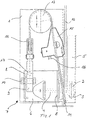
- a door leaf 1 is shown schematically, which in the closed position has a roller 2 in its lower side edge area, which in are each guided a track 3, which run in the vertical direction.
- the rollers 2 are connected to the door leaf 1 via stub axle 4.
- the rails 3 are attached to frame parts 5, which in turn within a building opening arranged on masonry, not shown in the figures are.
- a carrier 6 On the inside of the door leaf 1, a carrier 6 is arranged, which one has mechanical safety device 7, which is described in detail below becomes.
- the carrier 6 is plate-shaped and points to it Narrow side kinks 8, which are essentially parallel to each other run and essentially at right angles to the inner surface of the door leaf 1 are arranged.
- the mechanical catching device 7 has a pawl 9, which is connected by a bolt 10 pivotally attached to a side web 8 of the carrier 6 is.
- the pawl 9 is at one end facing away from the carrier 6 via a Fastening element 11 connected to a support cable 12, which with its Fastening element 11 facing away from an end, not shown, by means of a torsion spring biased shaft is attached.
- the suspension cable runs for this starting from the fastening element 11 via a deflection roller 13 and a Deflection 14, which is preferably designed as a roller and between the roller 2 and the side edge of the door leaf 1 facing this roller is.
- the support cable 12 thus runs at least with a partial area parallel to the frame part 5.
- the deflection roller 13 is parallel to the side edge having the deflection 14 of the door leaf 1 slidably attached to the door leaf 1, so that, for example by means of the deflection roller 13, a predetermined tension in the suspension cable 12 is set can be maintained if the rope becomes slack at first the cable tension is sensed by means of an electrical catching device (15) becomes.
- This electrical catching device is between the deflection roller 13 and the deflection 14 15 turned on in the support cable 12, which with a cable 16 a drive motor, not shown, is connected.
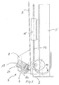
- the pawl 9 has one bore 17 aligned parallel to the surface normal of the door leaf 1, in which a spring 18 is inserted, which has one end on the carrier 6th supports, the spring 18 is biased when the suspension cable 12 is tensioned.
- the in essentially L-shaped pawl 9 is around by the bolt connection 10 shown pivot point rotatably, the pawl 9 on its end opposite the fastening element 11 on a pivotable Catch member 19 supports, which is pivotable about a pivot axis 20 is, the pivot axis 20 parallel to that through the bolt connection 10 formed pivot axis runs.
- the catch member 19 has a shoulder 21, which interacts with the jack 9.
- a cutting edge 22 is made Steel attached, which is aligned towards the running rail 3 and itself with slack suspension rope 12 by the weight of the moving in the closed position Door leaf 1 digs into the running rail 3, so that the cutting edge 22 at activated mechanical catching device 7 with a positive connection of the running rail 3, which prevents the door leaf 1 from falling further.
- the catch member 19 In order to enable safe triggering of the pivotable catch element 19, is the catch member 19 with a spring, not shown - preferably Leg spring - connected, which rotates the catch member 19 about the pivot axis 20, if the pawl 9 disengages from the paragraph 21.
- the drive motor switches off when the suspension cable 12 becomes slack.
- the electrical safety device 15 has a not shown Slack rope securing element, which measures the tension of the supporting rope 12 and when the suspension cable 12 becomes slack, the suspension cable 12 initially holds taut, so that the reduced suspension cable tension does not occur over a certain period of time the downstream mechanical catching device 7 is transmitted.
- Slack rope securing element which measures the tension of the supporting rope 12 and when the suspension cable 12 becomes slack, the suspension cable 12 initially holds taut, so that the reduced suspension cable tension does not occur over a certain period of time the downstream mechanical catching device 7 is transmitted.
- This mode of operation is given if, for example, one out of two Springs break, which keep the winding shaft under tension, so that only for a short time the suspension cable 12 becomes slack.
- the sharp-edged cutting edge 22 preferably engages the outer curvature of the Track 3, where the intervention takes place as possible against a roller 2, so that sufficient back pressure is exerted on the running rail 3, the a, avoiding the engagement of the cutting edge 2 avoiding the track 3 with special needs.
- the series connection of the electrical safety gear 15 is essential in front of the mechanical safety gear 7, so that an inevitable sequence of the two Safety gear 7 and 15 is given, which is initially the electrical safety gear 15 and then triggers the mechanical catching device 17.
- the mechanical Catch device 7 is also designed such that according to her Trigger a renewed commissioning or movement of the door leaf 1 by the Drive motor, not shown, from the catch position is not possible. Rather, the mechanical catching device 7 must be very specifically after removal all errors that have occurred are in their waiting position again, i.e. out of action with the track 3, are transferred. This transfer takes place in the Usually by hand, so that it is ensured that the drive motor starts is impossible before eliminating all sources of error. It can also be provided be that a signal is triggered by means of the mechanical catching device 7 is that a new start of the drive motor after triggering the mechanical Catcher 7 makes impossible.
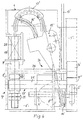
- the triggering element is the catching device here designed as a slide 9 ', which is a columnar central part 9 '' and its dimensions laterally projecting web plates 9 '' 'and on the support 6 'in a straight line in the direction of movement of the door leaf is stored.
- the rope 12 ' passes through a sleeve supported on the carrier 6' 28, the other end engages the upper web plate 9 '' 'and that of one Helical compression spring 18 'is encompassed.
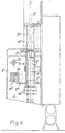
- the catch member 19 ' comprises a stop part 19' 'with an axis 25 rectangular cross section with a catch eccentric 19 '' 'to a twist-proof Unit is connected, as can be seen in particular in Figures 5 and 6.
- the catch eccentric is in a circumferential area which is in the catch position the running rail 3 'is pivoted too, provided with pointed tooth-like projections, here three 23 23 '23' ', in the order of their swivel position the track 3 is formed to protrude increasingly radially and from the Not shown engagement position seen in the direction of the closed position of the Door leaf are inclined so that there is a barbed effect for the Movement to the closed position results.
- the catch member 19 ' is assigned a blocking member 24 which has a blocking eccentric 24 ', which is rotatably supported by an axis 26.
- the blocking eccentric 24 ' corresponds to the catch eccentric 19' '' in a mirror-image arrangement, as can be seen in particular in FIG. 5.
- the two eccentrics are geared connected by teeth 30 and 31, which in each of the eccentrics in the Direction of rotation seen over a partial circumferential area in front of the projections 23 ... or 27 ... are trained. Due to the interlocking teeth 30 31 is the catch eccentric when the catch member is triggered under a pretensioned spring executed rotary movement - in Figure 5 counterclockwise the blocking eccentric 24 '- clockwise in Figure 5 - so that both projections 23 ... and 27 ... come into engagement with the running rail 3 '. Because of the inclination of the running rail 3 'with respect to the vertical, the axis is 26 of the blocking member 24 with respect to the axis 25 by one in FIG. 5 x designated route offset.
- FIGS. 4 to 7 show, are otherwise in relation to the first exemplary embodiment structural modifications for the second embodiment has been made, so the training adapted to the other catching device 7 ' of the carrier 6 ', the formation of the lower edge deflection device 14 'for the rope 12' and the formation of the upper deflection for the rope in the form of a skid 13 '.
- the electrical catching device 15 ' is preferably correct with that of the first embodiment.
Landscapes
- Engineering & Computer Science (AREA)
- Mechanical Engineering (AREA)
- Power-Operated Mechanisms For Wings (AREA)
- Maintenance And Inspection Apparatuses For Elevators (AREA)
- Lift-Guide Devices, And Elevator Ropes And Cables (AREA)
Claims (10)
- Installation de surveillance d'un câble de support (12) d'un panneau de porte (1), relevable, guidé par des galets de roulement (2) dans des rails de roulement (3), comprenant une installation électrique d'accrochage (15) qui coopère avec le câble de support (12) et est reliée à un moteur entraínant le panneau de porte (1), ce moteur étant coupé par l'installation électrique d'accrochage (15) lorsque le câble prend du mou, et une installation mécanique d'accrochage (7) comportant un élément d'accrochage (19) monté sur le panneau de porte (1) et qui lorsque le câble prend du mou, arrive en appui d'accrochage avec un élément fixe par rapport au panneau de porte (1) pour retenir le panneau de porte (1),
l'installation électrique d'accrochage (15) et réinstallation mécanique d'accrochage (7) étant branchées en série pour que l'installation électrique (15) d'accrochage se mette en oeuvre avant l'installation mécanique d'accrochage (7). - Installation de surveillance selon la revendication 1,
caractérisée en ce que
l'élément d'accrochage (19, 19') s'appuie, dans le sens d'une venue en prise contre un élément fixe notamment le rail de roulement (3), étant chargé par un ressort de préférence par un ressort à branches, lorsque le câble (12, 12') est tendu, contre une butée (21, 21') d'un élément de déclenchement, notamment un verrou (9) ou un coulisseau (9'), et qui lorsque le câble (12, 12') se détend, libère l'élément d'accrochage (19, 19') qui bascule en prise notamment par une liaison de forme. - Installation de surveillance selon la revendication 1 ou 2,
caractérisée en ce que
l'élément d'accrochage (19') comporte un excentrique d'accrochage (19"') notamment un organe tournant monté de manière excentrique, qui est muni d'une saillie (23, 23', 23"), qui dépasse de préférence en forme de dents, au niveau tourné vers l'objet fixe de préférence le rail de roulement (3), cette saillie étant au moins sensiblement radiale par rapport à l'axe de rotation de l'excentrique et qui en cas d'accrochage est conduit en appui contre l'objet antagoniste, sous l'effet de la force de ressort, et s'enfonce sous le poids du panneau de porte (1) conduit en position de fermeture, dans la zone d'accrochage de l'objet antagoniste de préférence dans la partie bombée extérieure du rail de roulement (3) notamment au voisinage d'un galet de roulement opposé (2, 2'). - Installation de surveillance selon la revendication 1 ou 2,
caractérisée en ce que
l'élément d'accrochage (19) comporte une arête (22), notamment en acier qui, sous l'effet de la force du ressort est pressée contre l'objet antagoniste fixe, notamment le rail de roulement (3) et s'enfonce dans cet objet antagoniste fixe de préférence la partie bombée extérieure du rail de roulement (3), notamment au voisinage d'un rail de roulement antagoniste (2, 2') sous l'effet du panneau de porte (1) se déplaçant vers sa position de fermeture. - Installation de surveillance selon l'une des revendications 1 à 4,
caractérisée en ce que
l'installation électrique d'accrochage (15, 15') et/ou l'installation mécanique d'accrochage (7, 7') comportent un élément de protection contre un câble détendu qui détecte la tension du câble de tension (12, 12') et qui, lorsque le câble (12, 12') de support tend à prendre du mou, le maintient tout d'abord tendu et protège l'installation mécanique d'accrochage (7, 7') en aval pendant un certain temps contre le relâchement du câble de support, temps pendant lequel la coupure du groupe d'entraínement à moteur rétablit la tension du câble de support si le défaut provoquant provisoirement la disparition de la tension du câble est en dehors du câble de support et du groupe moteur. - Installation de surveillance selon l'une des revendications 1 à 15,
caractérisée en ce que
le câble de support (12, 12') passe sur un renvoi (14, 14') prévu dans la zone du bord inférieur du panneau de porte (1) et en ce qu'entre l'installation électrique d'accrochage (15, 15') et l'installation mécanique de prise (7, 7'), sur le côté intérieur du panneau de porte (1), il y a une autre installation de renvoi (galet de renvoi (13) ou patin de renvoi (13')) pour le câble de support (12, 12'), notamment déplaçable sensiblement verticalement par rapport à l'arête de fermeture du panneau de porte. - Installation de surveillance selon l'une des revendications 1 à 6,
caractérisée en ce qu'
un élément de blocage (24) avec un excentrique de blocage (24') est associé à l'élément d'accrochage (19') et est relié à celui-ci en transmission qui en cas d'accrochage dans la direction opposée, lors d'un début de coulissement dans le sens de l'ouverture du panneau de porte (1), agit en se bloquant contre l'objet antagoniste fixe, notamment le rail de roulement (3). - Installation de surveillance selon la revendication 7,
caractérisée en ce que
l'excentrique d'accrochage (19"') et l'excentrique de blocage (24') sont portés par des axes (25, 26) sensiblement parallèles et pénètrent l'un dans l'autre chaque fois par des dents (30, 31) réalisées de manière sensiblement périphérique sur une partie de la périphérie, ces dents étant prévues en amont des saillies en forme de dents (23, 23', 23", 27, 27', 27") dans le sens de rotation, pour venir en prise avec l'objet antagoniste fixe, notamment le rail de roulement (3), et de préférence là ou les parties en saillie (23, 23', 23") de l'excentrique d'accrochage (19"') sont inclinées par rapport à la direction radiale dans le sens de la fermeture et les parties en saillie (27, 27', 27") de l'excentrique de blocage (24') sont inclinées vers la position d'ouverture du panneau de porte (1). - Installation de surveillance selon l'une des revendications 1 à 8,
caractérisée en ce que
l'excentrique d'accrochage (19"') est engagé solidairement en rotation comme disque sur un axe à quatre pans (25). - Installation de surveillance selon l'une des revendications 1 à 9,
caractérisée en ce que
l'élément de déclenchement (verrou (9) ou coulisseau (9')) est chargé par un ressort précontraint (18, 18') notamment un ressort hélicoïdal de pression.
Applications Claiming Priority (4)
| Application Number | Priority Date | Filing Date | Title |
|---|---|---|---|
| DE19500240 | 1995-01-05 | ||
| DE19500240 | 1995-01-05 | ||
| DE19507323A DE19507323C2 (de) | 1995-01-05 | 1995-03-02 | Überwachungseinrichtung für ein Tragseil eines Torblattes |
| DE19507323 | 1995-03-02 |
Publications (2)
| Publication Number | Publication Date |
|---|---|
| EP0721043A1 EP0721043A1 (fr) | 1996-07-10 |
| EP0721043B1 true EP0721043B1 (fr) | 1999-04-14 |
Family
ID=26011467
Family Applications (1)
| Application Number | Title | Priority Date | Filing Date |
|---|---|---|---|
| EP96100122A Expired - Lifetime EP0721043B1 (fr) | 1995-01-05 | 1996-01-05 | Dispositif de surveillance pour un câble porteur d'un panneau de porte |
Country Status (4)
| Country | Link |
|---|---|
| EP (1) | EP0721043B1 (fr) |
| AT (1) | ATE178968T1 (fr) |
| DK (1) | DK0721043T3 (fr) |
| ES (1) | ES2129894T3 (fr) |
Families Citing this family (6)
| Publication number | Priority date | Publication date | Assignee | Title |
|---|---|---|---|---|
| CA2419185A1 (fr) | 2003-02-19 | 2004-08-19 | Pierre-Louis Foucault | Dispositif de securite en cas de rupture de cable de porte de garage et d'element semblable |
| NO20045605D0 (no) * | 2004-12-22 | 2004-12-22 | Lonevag Beslagfabrikk As | Bunnbrakett for fallsikring av en garasjeport |
| CN103452458A (zh) * | 2013-08-01 | 2013-12-18 | 江苏荣泰门业有限公司 | 带有钢丝绳监控装置的柔性门 |
| DE102019208180B3 (de) * | 2019-06-05 | 2020-08-20 | Brühl Safety GmbH | Absturzsicherung für ein Hubtor, insbesondere Maschinenschutzhubtor |
| CN114729555B (zh) | 2019-11-20 | 2024-12-03 | 亚萨合莱自动门系统有限公司 | 角部支架 |
| CN120097203A (zh) * | 2025-05-12 | 2025-06-06 | 保利长大工程有限公司 | 一种匝道梁板架设用吊装装置 |
Family Cites Families (1)
| Publication number | Priority date | Publication date | Assignee | Title |
|---|---|---|---|---|
| DE3800404A1 (de) * | 1988-01-09 | 1989-07-20 | Werner Bothe | Vorrichtung zur sicherung von sektionaltoren oder dergleichen |
-
1996
- 1996-01-05 EP EP96100122A patent/EP0721043B1/fr not_active Expired - Lifetime
- 1996-01-05 ES ES96100122T patent/ES2129894T3/es not_active Expired - Lifetime
- 1996-01-05 DK DK96100122T patent/DK0721043T3/da active
- 1996-01-05 AT AT96100122T patent/ATE178968T1/de not_active IP Right Cessation
Also Published As
| Publication number | Publication date |
|---|---|
| EP0721043A1 (fr) | 1996-07-10 |
| ES2129894T3 (es) | 1999-06-16 |
| DK0721043T3 (da) | 1999-10-25 |
| ATE178968T1 (de) | 1999-04-15 |
Similar Documents
| Publication | Publication Date | Title |
|---|---|---|
| EP1102910B1 (fr) | Appareil de surveillance de ressort | |
| EP0151427B1 (fr) | Appareil de contrôle pour ressort d'équilibrage | |
| EP2925947B1 (fr) | Porte roulante présentant un vantail en forme de rideau souple | |
| EP1659298B1 (fr) | Entraînement linéaire | |
| EP1965018B1 (fr) | Porte dotée d'un équilibrage du ressort de traction et dispositif d'entraînement correspondant | |
| EP2131003B1 (fr) | Agencement d'arbres rotatifs pour une porte, notamment pour une porte roulante et une telle porte | |
| DE3843917C2 (fr) | ||
| EP0231227B1 (fr) | Dispositif d'accouplement pour l'arbre enrouleur d'une ceinture de securite a inertie avec dispositif de retenue | |
| DE202005015166U1 (de) | Schwenkschiebetür für Fahrzeuge, insbesondere Fahrgasttür für Fahrzeuge des öffentlichen Personennahverkehrs | |
| EP0127749A2 (fr) | Dispositif de sécurité contre le levage et store à lamelles comportant un tel dispositif | |
| EP0721043A1 (fr) | Dispositif de surveillance pour un câble porteur d'un panneau de porte | |
| EP3865651B1 (fr) | Entraînement pour une porte coulissante, porte coulissante pivotante ou marche coulissante avec verrouillage, porte coulissante, porte coulissante pivotante ou marche coulissante et véhicule | |
| EP0698174B1 (fr) | Securite anti-chute pour portes ou volets roulants | |
| EP0731247A2 (fr) | Dispositif de sécurité d'un volet enroulable autour d'un arbre | |
| DE19507323C2 (de) | Überwachungseinrichtung für ein Tragseil eines Torblattes | |
| DE102007037892A1 (de) | Tor mit Zugfederausgleich sowie Antriebsvorrichtung hierfür | |
| EP0722031A1 (fr) | Dispositif de surveillance d'un ressort de torsion précontraint | |
| DE29502273U1 (de) | Getriebe mit selbsttätig wirkender Fangvorrichtung | |
| DE102007033412A1 (de) | Rolltor | |
| DE69702420T2 (de) | Vorrichtung zum Heben einer vertikal beweglichen Tür | |
| EP1225292A2 (fr) | Porte | |
| EP4204656B1 (fr) | Système de sécurité conçu pour un entraînement, équipé d'un mécanisme de traction à circulation, d'une porte, en particulier d'une porte levante, plus particulièrement d'une porte levante à haute vitesse, et porte comprenant ledit système de sécurité | |
| DE2708221C2 (de) | Antrieb für ein Tor | |
| DE10052967A1 (de) | Chrashschutzvorrichtung für Schnelllaufrolltore | |
| DE4128112A1 (de) | Sperrvorrichtung zwischen motor und getriebe |
Legal Events
| Date | Code | Title | Description |
|---|---|---|---|
| PUAI | Public reference made under article 153(3) epc to a published international application that has entered the european phase |
Free format text: ORIGINAL CODE: 0009012 |
|
| AK | Designated contracting states |
Kind code of ref document: A1 Designated state(s): AT BE CH DE DK ES FR GB IE IT LI NL SE |
|
| 17P | Request for examination filed |
Effective date: 19960718 |
|
| RBV | Designated contracting states (corrected) |
Designated state(s): AT BE CH DE DK ES FR GB IE IT LI NL SE |
|
| GRAG | Despatch of communication of intention to grant |
Free format text: ORIGINAL CODE: EPIDOS AGRA |
|
| 17Q | First examination report despatched |
Effective date: 19980505 |
|
| GRAG | Despatch of communication of intention to grant |
Free format text: ORIGINAL CODE: EPIDOS AGRA |
|
| GRAH | Despatch of communication of intention to grant a patent |
Free format text: ORIGINAL CODE: EPIDOS IGRA |
|
| GRAH | Despatch of communication of intention to grant a patent |
Free format text: ORIGINAL CODE: EPIDOS IGRA |
|
| ITF | It: translation for a ep patent filed | ||
| GRAA | (expected) grant |
Free format text: ORIGINAL CODE: 0009210 |
|
| AK | Designated contracting states |
Kind code of ref document: B1 Designated state(s): AT BE CH DE DK ES FR GB IE IT LI NL SE |
|
| REF | Corresponds to: |
Ref document number: 178968 Country of ref document: AT Date of ref document: 19990415 Kind code of ref document: T |
|
| REG | Reference to a national code |
Ref country code: CH Ref legal event code: NV Representative=s name: PATENTANWALTSBUERO EDER AG Ref country code: CH Ref legal event code: EP |
|
| REG | Reference to a national code |
Ref country code: IE Ref legal event code: FG4D Free format text: GERMAN |
|
| REF | Corresponds to: |
Ref document number: 59601632 Country of ref document: DE Date of ref document: 19990520 |
|
| REG | Reference to a national code |
Ref country code: ES Ref legal event code: FG2A Ref document number: 2129894 Country of ref document: ES Kind code of ref document: T3 |
|
| ET | Fr: translation filed | ||
| GBT | Gb: translation of ep patent filed (gb section 77(6)(a)/1977) |
Effective date: 19990716 |
|
| REG | Reference to a national code |
Ref country code: DK Ref legal event code: T3 |
|
| PG25 | Lapsed in a contracting state [announced via postgrant information from national office to epo] |
Ref country code: IE Free format text: LAPSE BECAUSE OF NON-PAYMENT OF DUE FEES Effective date: 20000105 Ref country code: GB Free format text: LAPSE BECAUSE OF NON-PAYMENT OF DUE FEES Effective date: 20000105 Ref country code: DK Free format text: LAPSE BECAUSE OF NON-PAYMENT OF DUE FEES Effective date: 20000105 Ref country code: AT Free format text: LAPSE BECAUSE OF NON-PAYMENT OF DUE FEES Effective date: 20000105 |
|
| PG25 | Lapsed in a contracting state [announced via postgrant information from national office to epo] |
Ref country code: SE Free format text: LAPSE BECAUSE OF NON-PAYMENT OF DUE FEES Effective date: 20000106 |
|
| PG25 | Lapsed in a contracting state [announced via postgrant information from national office to epo] |
Ref country code: ES Free format text: LAPSE BECAUSE OF NON-PAYMENT OF DUE FEES Effective date: 20000107 |
|
| PG25 | Lapsed in a contracting state [announced via postgrant information from national office to epo] |
Ref country code: LI Free format text: LAPSE BECAUSE OF NON-PAYMENT OF DUE FEES Effective date: 20000131 Ref country code: CH Free format text: LAPSE BECAUSE OF NON-PAYMENT OF DUE FEES Effective date: 20000131 Ref country code: BE Free format text: LAPSE BECAUSE OF NON-PAYMENT OF DUE FEES Effective date: 20000131 |
|
| PLBE | No opposition filed within time limit |
Free format text: ORIGINAL CODE: 0009261 |
|
| STAA | Information on the status of an ep patent application or granted ep patent |
Free format text: STATUS: NO OPPOSITION FILED WITHIN TIME LIMIT |
|
| 26N | No opposition filed | ||
| BERE | Be: lapsed |
Owner name: MARANTEC ANTRIEBS- UND STEUERUNGSTECHNIK G.M.B.H. Effective date: 20000131 |
|
| PG25 | Lapsed in a contracting state [announced via postgrant information from national office to epo] |
Ref country code: NL Free format text: LAPSE BECAUSE OF NON-PAYMENT OF DUE FEES Effective date: 20000801 |
|
| GBPC | Gb: european patent ceased through non-payment of renewal fee |
Effective date: 20000105 |
|
| EUG | Se: european patent has lapsed |
Ref document number: 96100122.9 |
|
| REG | Reference to a national code |
Ref country code: CH Ref legal event code: PL |
|
| NLV4 | Nl: lapsed or anulled due to non-payment of the annual fee |
Effective date: 20000801 |
|
| REG | Reference to a national code |
Ref country code: DK Ref legal event code: EBP |
|
| PG25 | Lapsed in a contracting state [announced via postgrant information from national office to epo] |
Ref country code: DE Free format text: LAPSE BECAUSE OF NON-PAYMENT OF DUE FEES Effective date: 20001101 |
|
| REG | Reference to a national code |
Ref country code: IE Ref legal event code: MM4A |
|
| PG25 | Lapsed in a contracting state [announced via postgrant information from national office to epo] |
Ref country code: FR Free format text: LAPSE BECAUSE OF NON-PAYMENT OF DUE FEES Effective date: 20010928 |
|
| REG | Reference to a national code |
Ref country code: ES Ref legal event code: FD2A Effective date: 20010910 |
|
| REG | Reference to a national code |
Ref country code: FR Ref legal event code: ST |
|
| PG25 | Lapsed in a contracting state [announced via postgrant information from national office to epo] |
Ref country code: IT Free format text: LAPSE BECAUSE OF NON-PAYMENT OF DUE FEES Effective date: 20050105 |
|
| PG25 | Lapsed in a contracting state [announced via postgrant information from national office to epo] |
Ref country code: FR Free format text: LAPSE BECAUSE OF NON-PAYMENT OF DUE FEES Effective date: 20000131 |