EP0721737A2 - Machine à diviser et bouler la pâte - Google Patents
Machine à diviser et bouler la pâte Download PDFInfo
- Publication number
- EP0721737A2 EP0721737A2 EP95116468A EP95116468A EP0721737A2 EP 0721737 A2 EP0721737 A2 EP 0721737A2 EP 95116468 A EP95116468 A EP 95116468A EP 95116468 A EP95116468 A EP 95116468A EP 0721737 A2 EP0721737 A2 EP 0721737A2
- Authority
- EP
- European Patent Office
- Prior art keywords
- chamber
- delivery
- measuring
- dough
- piston
- Prior art date
- Legal status (The legal status is an assumption and is not a legal conclusion. Google has not performed a legal analysis and makes no representation as to the accuracy of the status listed.)
- Granted
Links
- 238000009940 knitting Methods 0.000 claims description 29
- 238000004513 sizing Methods 0.000 abstract 3
- 238000004898 kneading Methods 0.000 abstract 1
- 238000006073 displacement reaction Methods 0.000 description 2
- 230000000284 resting effect Effects 0.000 description 2
- 235000013312 flour Nutrition 0.000 description 1
Images


Classifications
-
- A—HUMAN NECESSITIES
- A21—BAKING; EDIBLE DOUGHS
- A21C—MACHINES OR EQUIPMENT FOR MAKING OR PROCESSING DOUGHS; HANDLING BAKED ARTICLES MADE FROM DOUGH
- A21C7/00—Machines which homogenise the subdivided dough by working other than by kneading
- A21C7/005—Machines which homogenise the subdivided dough by working other than by kneading the dough pieces being worked in radially disposed cavities in a rotating drum
-
- A—HUMAN NECESSITIES
- A21—BAKING; EDIBLE DOUGHS
- A21C—MACHINES OR EQUIPMENT FOR MAKING OR PROCESSING DOUGHS; HANDLING BAKED ARTICLES MADE FROM DOUGH
- A21C5/00—Dough-dividing machines
- A21C5/02—Dough-dividing machines with division boxes and ejection plungers
- A21C5/04—Dough-dividing machines with division boxes and ejection plungers with division boxes in a revolving body with radially-working pistons
Definitions
- the invention relates to a dough dividing and knitting machine.
- Dough dividing and knitting machines as are known, for example, from DE 41 42 931 A (corresponding to US Pat. No. 5,242,698), have a dough hopper and a downstream feed chamber with a reciprocatingly driven delivery piston which is used for filling of several measuring chambers arranged in a rotary valve.
- a measuring piston is arranged in each of the measuring chambers, which is displaced during the filling stroke and which, on the other hand, ejects a piece of dough from the respective measuring chamber during the return stroke of the delivery pistons while simultaneously rotating the rotary slide valve.
- the dough pieces then fall into knitting chambers of a knitting device. After being knitted, the knitted dough pieces are output via a transport device and, for example, fed to a proofing cabinet.
- the invention is therefore based on the object of designing a dough dividing and knitting machine in such a way that dough pieces of different recipe can be produced side by side at the same time.
- the measures according to the invention ensure that the doughs of different recipes do not touch each other, but that different dough pieces can be produced from the different doughs simultaneously.
- the further configuration according to the subclaims enables the dough pieces made from doughs of different recipes to also have different weights.
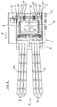
- the dough dividing and knitting machine shown in the drawing has an approximately rectangular frame 1 with side walls 2, 3.
- a dough dividing device 4, a knitting device 5 and a transport device 6 are arranged in the frame 1.
- the dough part device 4 has two conveying chambers 8, 9, which are arranged next to one another and are separated from one another by a dividing wall 7, on each of which a dough hopper 10 or 11 is attached, which can also be formed as a unit divided only by an intermediate wall 12.
- a delivery piston 13 or 14 is displaceable in the delivery direction 15 and opposite to the delivery direction.
- the delivery pistons 13, 14 are driven by a drive motor 16 which is arranged in the lower region of the frame 1 and is designed, for example, as a geared motor.
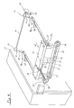
- a crank drive 18 is driven by the drive motor 16 via a chain drive 17. From this a push rod 19 is driven back and forth, which in turn is articulated on a pivot lever 20 which is fixedly connected to an oscillating shaft 21 which is rotatably mounted in bearings 22 which in turn are mounted in the side walls 2, 3 of the frame 1 are.
- On the oscillating shaft 21, two oscillating levers 23, 24 are attached by means of a releasable clamping device 25, so that the angular position of the oscillating levers 23, 24 can be adjusted relative to one another.
- the free ends of the rocker arms 23, 24 facing away from the rocker shaft 21 are each connected to a feed piston 13 and 14 by means of a pivot connection 26.
- the crank mechanism 18 rotates, the delivery pistons 13, 14 thus make a full stroke in the delivery direction 15 and a corresponding return stroke counter to the delivery direction 15.
- the push rod 19 is designed as a hydraulically actuated piston-cylinder drive, the cylinder 27 of which is articulated, for example, on the pivoting lever 20, while the piston rod 28 is articulated on the crank mechanism 18.
- the cylinder 27 is connected via a pressure line 29 to an adjustable pressure relief valve 30. If the counterforce acting on the delivery pistons 13, 14 during a delivery stroke in the direction of delivery 15 is so great that the hydraulic pressure in the cylinder 27 exceeds a predetermined value set at the pressure relief valve 30, then this pressure relief valve 30 opens and the delivery stroke of the delivery pistons 13, 14 becomes interrupted, ie the delivery pistons 13, 14 remain in their position and, when the crank mechanism 18 is turned further, are only taken along again on the return stroke counter to the delivery direction 15. Since pressure relief occurs in the cylinder 27, the pressure control valve 30 is closed again accordingly, the next time the delivery pistons 13, 14 are moved in the delivery direction 15, the push rod 19 has its original length again.
- a rotary slide valve 31 which can be pivoted about an axis 32.
- a measuring unit 33 in which a plurality of measuring chambers 34 are formed which have the same diameter.
- the measuring unit 33 is connected by means of screws 35 to the rotary slide valve 31, so that it can be easily exchanged for another measuring unit 33 with measuring chambers 34 which have a smaller or a larger diameter.
- measuring pistons 36 are slidably arranged, which have a piston surface 37, the curvature of which corresponds to the curvature of the rotary slide valve 31.
- the measuring pistons 36 have a plunger 38 which protrudes from the rotary slide valve 31 and bears at its end opposite the piston surface 37 with a pressure surface 39 against a control roller 40 or 41, the measuring piston 36 associated with the delivery chamber 8 being assigned a control roller 40, a further control roller 41 is assigned to the measuring pistons 36 assigned to the delivery chamber 9.
- the control rollers 40, 41 are each mounted in a pair of forks 42 which are attached to the rotary valve 31. They can be displaced radially in relation to the axis 32 of the rotary slide valve 31 in these forks 42.
- the size of the stroke of the measuring pistons 36 is predetermined by a weight adjustment device 43, by which the weight of a piece of dough 44 divided into a measuring chamber 34 is determined.
- This weight-adjusting device 43 has, in each case on a base body 45, pairs of cam pieces 46 and 47, the control roller 40 resting on a pair of curve pieces 46 and the control roller 41 resting on the other pair of curve pieces 47. If the rotary valve 31 is pivoted about its axis 32, then the respective control roller 40 or 41 is guided along the cam pieces 46 or 47, whereby the measuring piston 36 can perform a stroke, which will be discussed in more detail below.
- the base body 45 is slidably mounted in the frame 1 by means of a guide device 45a.
- a double-armed lever 49 is articulated at the end facing away from the base body 45 and is pivotably mounted in the side wall 2 or the side wall 3 by means of a swivel joint 50 .
- An actuating shaft 51 is rotatably mounted in the side walls 2, 3 of the frame 1, which is rotatable by means of a handwheel 52.
- two cams 53 are attached, which rest against adjusting pins 54 attached with the levers 49.
- This displacement of the base body 45 with the cam pieces 46 and 47 takes place in such a way that, when the rotary slide valve 31 is in a position with measuring chambers 34 open to the delivery chambers 8, 9, the piston surfaces 37 of the measuring piston 36 are always flush with the cylindrical surface 31a of the rotary slide valve 31 lie.
- the displacement of the base body 45 takes place against the force of a prestressed tension spring 48a, which on the one hand engages at least one push rod 48 and on the other hand on the frame 1, so that the adjusting pins 54 are constantly in contact with the respective cam plate 53.
- the curve pieces 47, against which the control roller 41 rests, are attached to a slide 55 which is mounted on the base body 45 so as to be displaceable in the direction of the push rods 48.
- An adjustment is carried out by means of a spindle 57 operated via a handwheel 56, or the like in a set position by means of nuts 58. can be locked in their set position.
- the adjusting shaft 51 or the levers 49 or the push rods 48 are locked in their set position by means of a clamping device 59.
- the rotary valve 31 is also driven by the drive motor 16 via the crank mechanism 18.
- a connecting rod 60 is articulated on the crank mechanism 18, at the other end of which a bent double-armed lever 61 is articulated, which is mounted eccentrically about an axis 62 in the frame 1.
- a push-pull rod 61a is articulated, which in turn is articulated on a pivot lever 63 which is fixedly connected to the rotary slide 31.
- the rotary valve 31 comes in on the one hand a position in which the measuring chambers 34 are open towards the delivery chambers 8 and 9, respectively. On the other hand, it comes into a position shown in FIG. 3, in which the measuring chambers 34 are open to the active device 5 arranged below them.
- the knitting device 5 usually has a knitting drum 64 which is concentrically surrounded by a chamber drum 65. knitting chambers 66 are formed in the chamber drum 65 towards the outside and towards the knitting drum 64, into which dough pieces 44 are placed.
- the chamber drum 65 is wrapped over part of its circumference by a knitting belt 67 which presses the dough pieces 44 against the knitting drum 64 and prevents them from falling out of the knitting chambers 66.
- the endlessly configured knitting belt 67 is guided over various deflection rollers 68 and a tensioning roller 69 and is carried along by the chamber drum 65, which can be driven in rotation, without slippage.
- the knitting drum 64 is in the direction of the common axis 70 of the knitting drum 64 and chamber drum 65 and in the tangential direction, i.e.
- the transport device 6 consists of spread endless conveyor belts 71 and 72 which are guided over deflection rollers 73 and a drive roller 74.
- the number of conveyor belts 71 corresponds to the number of measuring chambers 34 assigned to the conveying chamber 8; the number of conveyor belts 72 corresponds to the number of measuring chambers 34 assigned to the conveying chamber 9.
- the transport device 6 leads, for example, to a downstream proofing cabinet.
- a flour spreader 75 is assigned to the knitting belt 67.
- the machine shown and described works as follows: There is a type of dough 76 in the dough hopper 10; in the other dough hopper 11 there is another type of dough, not shown separately in the drawing.
- the dough 76 located in the respective dough hopper 10 or 11 is sucked into the delivery chambers 8 and 9 and fills them out, as in FIG 1 is shown.
- the delivery pistons 13, 14 are displaced in the direction of the rotary slide valve 31.
- the delivery pistons 13, 14 close the closed sections 8a and 9a of the delivery chambers 8, 9 when they no longer open to the respective dough hopper 10 or 11.
- the rotary slide valve 31 is in a position shown in FIG. 1, in which the measuring chambers 34 are open towards the respective delivery chamber 8 or 9. Due to the conveying stroke of the delivery pistons 13 and 14, the measuring chambers 34 are filled with dough 76, the measuring pistons 36 being displaced until the control roller 40 and 41 assigned to them bears against the cam sections 46 and 47, respectively. As a result, the stroke of the measuring piston 36 is limited and thus the volume and thus in turn the weight of the dough pieces 44 and 44a is determined. If, during this filling stroke or delivery stroke, the pressure in the closed sections 8a or 9a of the delivery chambers 8 or 9 becomes too high, then the pressure limiting valve 30 assigned to the push rod 19 opens, as already described above.
- Dough 76 of different recipe can be found in the two dough hoppers 10, 11. Those divided from the different doughs on the one hand from the delivery chamber 8 and on the other hand from the delivery chamber 9 Pieces of dough 44 and 44a can have different weights, since the weight setting can be different. The different pieces of dough 44, 44a can be removed separately after being knitted.
- the clamping devices 25 can be clamped against one another offset by a small angle on the oscillating shaft 21, so that one delivery piston 13 or 14 leads the other delivery piston 14 or 13 in the delivery stroke 15 in the delivery stroke. It is thereby achieved that the preset filling pressure in the delivery chamber 8 or 9 assigned to the advance delivery piston 13 or 14 is reached sooner than in the delivery chamber 9 or 8 assigned to the lagging delivery piston 14 or 13. As a result, the pressure relief valve 30 already opens when the preset filling pressure is reached in the delivery chamber 8 or 9 assigned to the advance delivery piston 13 or 14. A lower filling pressure is thus achieved in the delivery chamber 9 or 8 assigned to the lagging delivery piston 14 or 13. Since dough is a compressible material, this possibility can be exploited if two different types of dough with a very different consistency and a very different compressibility are used.
- two measuring units 33 can also be provided in the rotary slide valve 31, one of which is assigned to each delivery chamber 8 or 9. These measuring units can have measuring chambers 34 of different diameters.
Landscapes
- Life Sciences & Earth Sciences (AREA)
- Engineering & Computer Science (AREA)
- Food Science & Technology (AREA)
- Manufacturing And Processing Devices For Dough (AREA)
- Knitting Machines (AREA)
- Bakery Products And Manufacturing Methods Therefor (AREA)
Applications Claiming Priority (2)
| Application Number | Priority Date | Filing Date | Title |
|---|---|---|---|
| DE19500851 | 1995-01-13 | ||
| DE19500851A DE19500851A1 (de) | 1995-01-13 | 1995-01-13 | Teigteil- und Wirk-Maschine |
Publications (3)
| Publication Number | Publication Date |
|---|---|
| EP0721737A2 true EP0721737A2 (fr) | 1996-07-17 |
| EP0721737A3 EP0721737A3 (fr) | 1998-01-28 |
| EP0721737B1 EP0721737B1 (fr) | 2001-06-27 |
Family
ID=7751428
Family Applications (1)
| Application Number | Title | Priority Date | Filing Date |
|---|---|---|---|
| EP95116468A Expired - Lifetime EP0721737B1 (fr) | 1995-01-13 | 1995-10-19 | Machine à diviser et bouler la pâte |
Country Status (4)
| Country | Link |
|---|---|
| US (1) | US5897203A (fr) |
| EP (1) | EP0721737B1 (fr) |
| AT (1) | ATE202450T1 (fr) |
| DE (2) | DE19500851A1 (fr) |
Cited By (2)
| Publication number | Priority date | Publication date | Assignee | Title |
|---|---|---|---|---|
| EP1103183A2 (fr) | 1999-11-17 | 2001-05-30 | Werner & Pfleiderer Lebensmitteltechnik GmbH | Dispositif pour le pétrissage |
| WO2014066496A1 (fr) * | 2012-10-23 | 2014-05-01 | Multi-Fill, Inc. | Système et procédé d'alimentation en vrac |
Families Citing this family (10)
| Publication number | Priority date | Publication date | Assignee | Title |
|---|---|---|---|---|
| DE19624401B4 (de) * | 1996-06-19 | 2009-05-07 | Werner & Pfleiderer Lebensmitteltechnik Gmbh | Teigverarbeitungsanlage |
| ES2213996T3 (es) | 1999-12-08 | 2004-09-01 | Centre National De La Recherche Scientifique (Cnrs) | Uso de himenialdisina o sus derivados en la fabricacion de medicamentos. |
| DE20014945U1 (de) | 2000-08-30 | 2001-01-11 | Werner & Pfleiderer Lebensmitteltechnik GmbH, 91550 Dinkelsbühl | Stanzvorrichtung zum Formen von Teiglingen |
| US7837456B2 (en) * | 2007-10-11 | 2010-11-23 | Amf Automation Technologies, Inc. | Dough stream blocker |
| DE102007062386A1 (de) * | 2007-12-22 | 2009-06-25 | Werner & Pfleiderer Lebensmitteltechnik Gmbh | Teigbearbeitungsanlage |
| DE102014102289A1 (de) * | 2014-02-21 | 2015-08-27 | Oka-Spezialmaschinenfabrik Gmbh & Co. Kg | Motivwalze, Teigformmaschine und Verfahren zur Herstellung eines Gebäckstücks |
| JP6041365B2 (ja) * | 2015-02-16 | 2016-12-07 | 株式会社工揮 | 食品生地の分割装置 |
| AT519085B1 (de) * | 2016-10-07 | 2018-04-15 | Koenig Maschinen Gmbh | Programm-Zyklus gesteuerter Ablauf einer Teiltrommel für Teigteil und Wirkmaschine |
| DE102017215606A1 (de) * | 2017-09-05 | 2019-03-07 | Werner & Pfleiderer Lebensmitteltechnik Gmbh | Teigteilvorrichtung sowie Teigbearbeitungsanlage mit einer derartigen Teigteilvorrichtung |
| DE102022204186B3 (de) * | 2022-04-28 | 2023-10-26 | Werner & Pfleiderer Lebensmitteltechnik Gmbh | Teigteilvorrichtung |
Citations (2)
| Publication number | Priority date | Publication date | Assignee | Title |
|---|---|---|---|---|
| DE1126333B (de) | 1960-02-27 | 1962-03-22 | Werner & Pfleiderer | Teigteil- und Rundwirkmaschine |
| DE4142931A1 (de) | 1991-12-24 | 1993-07-01 | Werner & Pfleiderer | Verfahren und vorrichtung zur ansteuerung einer kopfmaschine und wenigstens einer nachfolgeeinrichtung |
Family Cites Families (11)
| Publication number | Priority date | Publication date | Assignee | Title |
|---|---|---|---|---|
| US3125039A (en) * | 1964-03-17 | Metering device for a dough kneading machine | ||
| DE622221C (de) * | 1932-05-03 | 1935-11-23 | Fridolin Winkler | Teigteilmaschine |
| GB521260A (en) * | 1938-11-10 | 1940-05-16 | William Warren Triggs | Improvements relating to mechanism for the delivery of measured quantities of dough or other plastic material |
| FR2113302A5 (en) * | 1970-10-29 | 1972-06-23 | Talleres Balart Sa | Dividing machine for dough - for use in bread mfr |
| AT332822B (de) * | 1971-09-13 | 1976-10-25 | Koenig Helmut | Vorrichtung zum portionieren von teig |
| FR2449273A1 (fr) * | 1979-02-16 | 1980-09-12 | Locolas Claude | Perfectionnements aux diviseuses volumetriques de matieres pateuses |
| FR2598647B1 (fr) * | 1986-05-13 | 1990-02-09 | Festa Michel | Dispositif permettant de separer des parts d'une matiere molle, pateuse ou granuleuse |
| AT392195B (de) * | 1988-12-20 | 1991-02-11 | Koenig Helmut | Vorrichtung zum wirken von portionierten teigstuecken |
| DE3933558A1 (de) * | 1989-10-07 | 1991-04-18 | Holter Gmbh & Co | Nockenblock fuer kontaktsteuerungen |
| US5217739A (en) * | 1991-05-13 | 1993-06-08 | General Mills, Inc. | Method of flipping and aligning a dough sheet |
| CA2113264C (fr) * | 1991-07-12 | 1997-03-25 | Helmut Konig | Dispositif de decoupage de portions de pate |
-
1995
- 1995-01-13 DE DE19500851A patent/DE19500851A1/de not_active Withdrawn
- 1995-10-19 AT AT95116468T patent/ATE202450T1/de not_active IP Right Cessation
- 1995-10-19 EP EP95116468A patent/EP0721737B1/fr not_active Expired - Lifetime
- 1995-10-19 DE DE59509362T patent/DE59509362D1/de not_active Expired - Fee Related
-
1996
- 1996-01-12 US US08/585,896 patent/US5897203A/en not_active Expired - Fee Related
Patent Citations (2)
| Publication number | Priority date | Publication date | Assignee | Title |
|---|---|---|---|---|
| DE1126333B (de) | 1960-02-27 | 1962-03-22 | Werner & Pfleiderer | Teigteil- und Rundwirkmaschine |
| DE4142931A1 (de) | 1991-12-24 | 1993-07-01 | Werner & Pfleiderer | Verfahren und vorrichtung zur ansteuerung einer kopfmaschine und wenigstens einer nachfolgeeinrichtung |
Cited By (3)
| Publication number | Priority date | Publication date | Assignee | Title |
|---|---|---|---|---|
| EP1103183A2 (fr) | 1999-11-17 | 2001-05-30 | Werner & Pfleiderer Lebensmitteltechnik GmbH | Dispositif pour le pétrissage |
| DE19955293B4 (de) * | 1999-11-17 | 2008-11-13 | Werner & Pfleiderer Lebensmitteltechnik Gmbh | Wirk-Vorrichtung |
| WO2014066496A1 (fr) * | 2012-10-23 | 2014-05-01 | Multi-Fill, Inc. | Système et procédé d'alimentation en vrac |
Also Published As
| Publication number | Publication date |
|---|---|
| DE59509362D1 (de) | 2001-08-02 |
| ATE202450T1 (de) | 2001-07-15 |
| EP0721737A3 (fr) | 1998-01-28 |
| EP0721737B1 (fr) | 2001-06-27 |
| DE19500851A1 (de) | 1996-07-18 |
| US5897203A (en) | 1999-04-27 |
Similar Documents
| Publication | Publication Date | Title |
|---|---|---|
| EP0721737B1 (fr) | Machine à diviser et bouler la pâte | |
| DE3610010A1 (de) | Vorrichtung zum abteilen von portionspackungen eines unterteilbaren fuellgutes in einer flexiblen schlauchhuelle | |
| EP0685396A1 (fr) | Dispositif de transport pour le transport intermittent de récipients | |
| EP1449438B1 (fr) | Installation de traitement de pâte | |
| DE3630077C2 (fr) | ||
| EP1447005A2 (fr) | Installation de traitement de pâte | |
| DE10238707A1 (de) | Teigteilmaschine | |
| EP0612660B1 (fr) | Dispositif de dosage de matières pulvérulentes plus spécifiquement | |
| DE2907568C2 (de) | Maschine zum Herstellen von gleichen Teigteilchen | |
| DE10009300A1 (de) | Verfahren und Einrichtung zum Herstellen von gleich großen runden Teigstücken | |
| DE10305378B4 (de) | Portioniereinheit | |
| DE69402454T2 (de) | Verdichtungseinheit für Gruppen von flachen Produkten angeordnet auf einer Kante Seite an Seite | |
| DE2915348C2 (de) | Vorrichtung zum Portionieren von Teig für Brötchen oder Kleienbrote | |
| DE2807188C2 (fr) | ||
| DE3011863A1 (de) | Vorrichtung zum portionieren von teig fuer broetchen oder kleinbrote | |
| DE3409517C2 (de) | Vorrichtung zum Fördern pastoser Massen | |
| DE2312360C3 (de) | Tragbare, handgeführte Vibrationsschleifmaschine | |
| DE3247621A1 (de) | Vorrichtung zum portionieren von teig fuer broetchen oder kleinbrote | |
| DE658052C (de) | Hydraulische Walzenheb- und Senkvorrichtung an Vollgattern und anderen Holzbearbeitungsmaschinen | |
| EP4442415A1 (fr) | Dispositif pour couper ou découper de la pâte | |
| AT383472B (de) | Vorrichtung zum gleichmaessigen portionieren von teig | |
| DE1452554A1 (de) | Metallformmaschine | |
| DE284878C (fr) | ||
| DE943104C (de) | Feinverstellung fuer Materialvorschub | |
| DE2613174B2 (de) | Vorrichtung zur Steuerung von Greifern in Bogenrotationsdruckmaschinen |
Legal Events
| Date | Code | Title | Description |
|---|---|---|---|
| PUAI | Public reference made under article 153(3) epc to a published international application that has entered the european phase |
Free format text: ORIGINAL CODE: 0009012 |
|
| AK | Designated contracting states |
Kind code of ref document: A2 Designated state(s): AT BE DE FR GB IT NL SE |
|
| PUAL | Search report despatched |
Free format text: ORIGINAL CODE: 0009013 |
|
| AK | Designated contracting states |
Kind code of ref document: A3 Designated state(s): AT BE DE FR GB IT NL SE |
|
| 17P | Request for examination filed |
Effective date: 19980116 |
|
| GRAG | Despatch of communication of intention to grant |
Free format text: ORIGINAL CODE: EPIDOS AGRA |
|
| GRAG | Despatch of communication of intention to grant |
Free format text: ORIGINAL CODE: EPIDOS AGRA |
|
| GRAH | Despatch of communication of intention to grant a patent |
Free format text: ORIGINAL CODE: EPIDOS IGRA |
|
| 17Q | First examination report despatched |
Effective date: 20001205 |
|
| GRAH | Despatch of communication of intention to grant a patent |
Free format text: ORIGINAL CODE: EPIDOS IGRA |
|
| GRAA | (expected) grant |
Free format text: ORIGINAL CODE: 0009210 |
|
| AK | Designated contracting states |
Kind code of ref document: B1 Designated state(s): AT BE DE FR GB IT NL SE |
|
| PG25 | Lapsed in a contracting state [announced via postgrant information from national office to epo] |
Ref country code: IT Free format text: LAPSE BECAUSE OF FAILURE TO SUBMIT A TRANSLATION OF THE DESCRIPTION OR TO PAY THE FEE WITHIN THE PRE;WARNING: LAPSES OF ITALIAN PATENTS WITH EFFECTIVE DATE BEFORE 2007 MAY HAVE OCCURRED AT ANY TIME BEFORE 2007. THE CORRECT EFFECTIVE DATE MAY BE DIFFERENT FROM THE ONE RECORDED.SCRIBED TIME-LIMIT Effective date: 20010627 |
|
| REF | Corresponds to: |
Ref document number: 202450 Country of ref document: AT Date of ref document: 20010715 Kind code of ref document: T |
|
| ET | Fr: translation filed | ||
| GBT | Gb: translation of ep patent filed (gb section 77(6)(a)/1977) |
Effective date: 20010629 |
|
| REF | Corresponds to: |
Ref document number: 59509362 Country of ref document: DE Date of ref document: 20010802 |
|
| PGFP | Annual fee paid to national office [announced via postgrant information from national office to epo] |
Ref country code: AT Payment date: 20010907 Year of fee payment: 7 |
|
| PGFP | Annual fee paid to national office [announced via postgrant information from national office to epo] |
Ref country code: GB Payment date: 20010912 Year of fee payment: 7 |
|
| PG25 | Lapsed in a contracting state [announced via postgrant information from national office to epo] |
Ref country code: SE Free format text: LAPSE BECAUSE OF FAILURE TO SUBMIT A TRANSLATION OF THE DESCRIPTION OR TO PAY THE FEE WITHIN THE PRESCRIBED TIME-LIMIT Effective date: 20010927 |
|
| PGFP | Annual fee paid to national office [announced via postgrant information from national office to epo] |
Ref country code: FR Payment date: 20011017 Year of fee payment: 7 |
|
| PGFP | Annual fee paid to national office [announced via postgrant information from national office to epo] |
Ref country code: NL Payment date: 20011026 Year of fee payment: 7 |
|
| PG25 | Lapsed in a contracting state [announced via postgrant information from national office to epo] |
Ref country code: BE Free format text: LAPSE BECAUSE OF NON-PAYMENT OF DUE FEES Effective date: 20011031 |
|
| PGFP | Annual fee paid to national office [announced via postgrant information from national office to epo] |
Ref country code: DE Payment date: 20011218 Year of fee payment: 7 |
|
| REG | Reference to a national code |
Ref country code: GB Ref legal event code: IF02 |
|
| BERE | Be: lapsed |
Owner name: WERNER & PFLEIDERER LEBENSMITTELTECHNIK G.M.B.H. Effective date: 20011031 |
|
| PLBE | No opposition filed within time limit |
Free format text: ORIGINAL CODE: 0009261 |
|
| STAA | Information on the status of an ep patent application or granted ep patent |
Free format text: STATUS: NO OPPOSITION FILED WITHIN TIME LIMIT |
|
| 26N | No opposition filed | ||
| PG25 | Lapsed in a contracting state [announced via postgrant information from national office to epo] |
Ref country code: GB Free format text: LAPSE BECAUSE OF NON-PAYMENT OF DUE FEES Effective date: 20021019 Ref country code: AT Free format text: LAPSE BECAUSE OF NON-PAYMENT OF DUE FEES Effective date: 20021019 |
|
| PG25 | Lapsed in a contracting state [announced via postgrant information from national office to epo] |
Ref country code: NL Free format text: LAPSE BECAUSE OF NON-PAYMENT OF DUE FEES Effective date: 20030501 Ref country code: DE Free format text: LAPSE BECAUSE OF NON-PAYMENT OF DUE FEES Effective date: 20030501 |
|
| GBPC | Gb: european patent ceased through non-payment of renewal fee |
Effective date: 20021019 |
|
| PG25 | Lapsed in a contracting state [announced via postgrant information from national office to epo] |
Ref country code: FR Free format text: LAPSE BECAUSE OF NON-PAYMENT OF DUE FEES Effective date: 20030630 |
|
| NLV4 | Nl: lapsed or anulled due to non-payment of the annual fee |
Effective date: 20030501 |
|
| REG | Reference to a national code |
Ref country code: FR Ref legal event code: ST |