EP0721818A1 - Verfahren und vorrichtung zur herstellung von laser-geschweissten röhren - Google Patents
Verfahren und vorrichtung zur herstellung von laser-geschweissten röhren Download PDFInfo
- Publication number
- EP0721818A1 EP0721818A1 EP95926013A EP95926013A EP0721818A1 EP 0721818 A1 EP0721818 A1 EP 0721818A1 EP 95926013 A EP95926013 A EP 95926013A EP 95926013 A EP95926013 A EP 95926013A EP 0721818 A1 EP0721818 A1 EP 0721818A1
- Authority
- EP
- European Patent Office
- Prior art keywords
- welding
- metal band
- laser
- cutting
- edges
- Prior art date
- Legal status (The legal status is an assumption and is not a legal conclusion. Google has not performed a legal analysis and makes no representation as to the accuracy of the status listed.)
- Granted
Links
Images









Classifications
-
- B—PERFORMING OPERATIONS; TRANSPORTING
- B23—MACHINE TOOLS; METAL-WORKING NOT OTHERWISE PROVIDED FOR
- B23K—SOLDERING OR UNSOLDERING; WELDING; CLADDING OR PLATING BY SOLDERING OR WELDING; CUTTING BY APPLYING HEAT LOCALLY, e.g. FLAME CUTTING; WORKING BY LASER BEAM
- B23K26/00—Working by laser beam, e.g. welding, cutting or boring
-
- B—PERFORMING OPERATIONS; TRANSPORTING
- B21—MECHANICAL METAL-WORKING WITHOUT ESSENTIALLY REMOVING MATERIAL; PUNCHING METAL
- B21C—MANUFACTURE OF METAL SHEETS, WIRE, RODS, TUBES, PROFILES OR LIKE SEMI-MANUFACTURED PRODUCTS OTHERWISE THAN BY ROLLING; AUXILIARY OPERATIONS USED IN CONNECTION WITH METAL-WORKING WITHOUT ESSENTIALLY REMOVING MATERIAL
- B21C37/00—Manufacture of metal sheets, rods, wire, tubes, profiles or like semi-manufactured products, not otherwise provided for; Manufacture of tubes of special shape
- B21C37/06—Manufacture of metal sheets, rods, wire, tubes, profiles or like semi-manufactured products, not otherwise provided for; Manufacture of tubes of special shape of tubes or metal hoses; Combined procedures for making tubes, e.g. for making multi-wall tubes
- B21C37/08—Making tubes with welded or soldered seams
- B21C37/083—Supply, or operations combined with supply, of strip material
-
- B—PERFORMING OPERATIONS; TRANSPORTING
- B21—MECHANICAL METAL-WORKING WITHOUT ESSENTIALLY REMOVING MATERIAL; PUNCHING METAL
- B21C—MANUFACTURE OF METAL SHEETS, WIRE, RODS, TUBES, PROFILES OR LIKE SEMI-MANUFACTURED PRODUCTS OTHERWISE THAN BY ROLLING; AUXILIARY OPERATIONS USED IN CONNECTION WITH METAL-WORKING WITHOUT ESSENTIALLY REMOVING MATERIAL
- B21C37/00—Manufacture of metal sheets, rods, wire, tubes, profiles or like semi-manufactured products, not otherwise provided for; Manufacture of tubes of special shape
- B21C37/06—Manufacture of metal sheets, rods, wire, tubes, profiles or like semi-manufactured products, not otherwise provided for; Manufacture of tubes of special shape of tubes or metal hoses; Combined procedures for making tubes, e.g. for making multi-wall tubes
- B21C37/08—Making tubes with welded or soldered seams
- B21C37/0807—Tube treating or manipulating combined with, or specially adapted for use in connection with tube making machines, e.g. drawing-off devices, cutting-off
- B21C37/0811—Tube treating or manipulating combined with, or specially adapted for use in connection with tube making machines, e.g. drawing-off devices, cutting-off removing or treating the weld bead
-
- B—PERFORMING OPERATIONS; TRANSPORTING
- B23—MACHINE TOOLS; METAL-WORKING NOT OTHERWISE PROVIDED FOR
- B23K—SOLDERING OR UNSOLDERING; WELDING; CLADDING OR PLATING BY SOLDERING OR WELDING; CUTTING BY APPLYING HEAT LOCALLY, e.g. FLAME CUTTING; WORKING BY LASER BEAM
- B23K13/00—Welding by high-frequency current heating
-
- B—PERFORMING OPERATIONS; TRANSPORTING
- B23—MACHINE TOOLS; METAL-WORKING NOT OTHERWISE PROVIDED FOR
- B23K—SOLDERING OR UNSOLDERING; WELDING; CLADDING OR PLATING BY SOLDERING OR WELDING; CUTTING BY APPLYING HEAT LOCALLY, e.g. FLAME CUTTING; WORKING BY LASER BEAM
- B23K13/00—Welding by high-frequency current heating
- B23K13/01—Welding by high-frequency current heating by induction heating
- B23K13/02—Seam welding
- B23K13/025—Seam welding for tubes
-
- B—PERFORMING OPERATIONS; TRANSPORTING
- B23—MACHINE TOOLS; METAL-WORKING NOT OTHERWISE PROVIDED FOR
- B23K—SOLDERING OR UNSOLDERING; WELDING; CLADDING OR PLATING BY SOLDERING OR WELDING; CUTTING BY APPLYING HEAT LOCALLY, e.g. FLAME CUTTING; WORKING BY LASER BEAM
- B23K26/00—Working by laser beam, e.g. welding, cutting or boring
- B23K26/20—Bonding
- B23K26/21—Bonding by welding
- B23K26/24—Seam welding
- B23K26/26—Seam welding of rectilinear seams
- B23K26/262—Seam welding of rectilinear seams of longitudinal seams of tubes
-
- B—PERFORMING OPERATIONS; TRANSPORTING
- B23—MACHINE TOOLS; METAL-WORKING NOT OTHERWISE PROVIDED FOR
- B23K—SOLDERING OR UNSOLDERING; WELDING; CLADDING OR PLATING BY SOLDERING OR WELDING; CUTTING BY APPLYING HEAT LOCALLY, e.g. FLAME CUTTING; WORKING BY LASER BEAM
- B23K26/00—Working by laser beam, e.g. welding, cutting or boring
- B23K26/20—Bonding
- B23K26/21—Bonding by welding
- B23K26/24—Seam welding
- B23K26/28—Seam welding of curved planar seams
- B23K26/282—Seam welding of curved planar seams of tube sections
-
- B—PERFORMING OPERATIONS; TRANSPORTING
- B23—MACHINE TOOLS; METAL-WORKING NOT OTHERWISE PROVIDED FOR
- B23K—SOLDERING OR UNSOLDERING; WELDING; CLADDING OR PLATING BY SOLDERING OR WELDING; CUTTING BY APPLYING HEAT LOCALLY, e.g. FLAME CUTTING; WORKING BY LASER BEAM
- B23K26/00—Working by laser beam, e.g. welding, cutting or boring
- B23K26/60—Preliminary treatment
Definitions
- the present invention relates to a method for producing welded tubes from metal bands by using laser welding and an apparatus for producing the same.
- Laser welding makes high-speed welding possible, since the welding method has higher energy density at its heat source and therefore has a deeper melting depth than other welding methods. In addition, since the total amount of heat input can be decreased, the performance at welded sections can be made superior. For these reasons, laser welding has become a focus of attention as a welding method for producing steel tubes and application of laser welding to production of steel tubes is proceeding. When producing welded tubes by laser welding, welding beads of which inner and outer surfaces are swollen are formed at the outer and/or inner surfaces of welded sections in the same way as other fusion welding methods. It is therefore necessary to cut these beads. However, because of the reasons described below, it was not easy to cut the welding beads, and the machinability of the welding beads was inferior.
- Laser welding is characterized in that the amount of welding heat input is small.
- the cooling speed of the welding beads after welding is high since the amount of welding heat input is small, and the temperature of the welding beads is fairly low at the cutting position.
- the welding beads having been cooled to a low temperature have high material strength and thus require high cutting force, thereby reducing the machinability thereof.
- chatter is generated on the cutting surfaces.
- a very hard built-up edge is apt to be generated at the tip of a cutting tool. In case that such a built-up edge is formed, gouge and chatter are generated on the cutting surfaces.
- the welding beads When the material of the metal band is non-austenitic steel, such as carbon steel, since the amount of welding heat input is small and the welding beads are cooled quickly, the welding beads may be sometimes subjected to martensitic transformation. In this case, the welding beads become very hard and cannot be cut.
- One object of the present invention is to provide a method for producing laser-welded tubes and an apparatus for producing the same, wherein the cutting of welding beads formed on a laser-welded tube having been produced can be done easily and the accuracy of the finished dimensions of the welded tube can be improved by preheating the metal band to be welded at the time of producing a welded tube by using laser welding.
- Another object of the invention is to provide a method for producing welded tubes and an apparatus for producing the same, wherein welding beads can be cut securely before the beads become hard by making a cutting tool movable in the transfer direction at a production line.
- the abutting edges of a metal band are preheated to a predetermined temperature before laser welding, the abutting edges of the metal band are then welded by laser welding and welding beads generated on the outer and/or inner surfaces of the welded tube having been produced are eliminated by cutting.
- the predetermined temperature is determined depending on the thickness of the metal band and the time from the start of laser welding to the cutting of the welding beads. More specifically, the temperature satisfies the following condition (1).
- T Predetermined temperature (°C) at the edges of the metal band before laser welding
- t Time (minutes) from the start of laser welding to the cutting of the welding beads
- a Thickness (mm) of a metal band to be welded
- Preheating the edges of the metal band before welding prevents the hardening of the welding beads due to quick cooling at the welded section after laser welding, thereby allowing the welding beads on the welded tube having been produced to be cut.
- the apparatus for producing laser-welded tubes in accordance with the invention has preheating means for preheating the edges of a metal band, laser-welding means for forming a welded tube by laser-welding the preheated abutting edges of the metal band, and cutting means for cutting and eliminating welding beads from the welded tube having been formed.
- the cutting tool of the cutting means is movable in the longitudinal direction of the welded tube.
- the apparatus is provided with adjusting means for adjusting the preheating power of the preheating means and/or an adjusting means for adjusting the speed of transfer at a production line, so as to satisfy the above-mentioned condition (1).
- the apparatus can easily satisfy the above-mentioned condition (1).
- the line speed is low, for example, time t from the start of laser welding to the elimination of the welding beads can be shortened by moving the cutting tool toward the laser welding means.
- the above-mentioned condition (1) is thus satisfied and the welding beads can be cut.
- FIG. 1 is a view showing the structure of an apparatus for producing laser-welded tubes in accordance with the invention
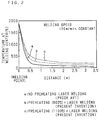
- FIG. 2 is a graph showing the temperature drops at welded sections in various welding methods
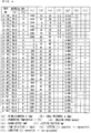
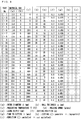
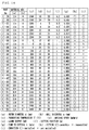
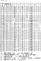
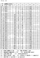
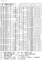
- FIG. 3 is a table showing the examples of the first test results obtained by using the method for producing laser-welded tubes in accordance the invention
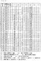
- FIG. 4 is a table showing the examples of the first test results obtained by using the method for producing laser-welded tubes in accordance with the invention
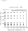
- FIG. 5 is a graph showing the examples of the first test results shown in FIGS. 4 and 5
- FIG. 6 is a table showing the examples of the second test results obtained by using the method for producing laser-welded tubes in accordance with the invention
- FIG. 1 is a view showing the structure of an apparatus for producing laser-welded tubes in accordance with the invention
- FIG. 2 is a graph showing the temperature drops at welded sections in various welding methods
- FIG. 3 is a table showing the examples of the first test results obtained by using the method for producing laser-welded tubes in accordance the invention
- FIG. 7 is a table showing the examples of the second test results obtained by using the method for producing laser-welded tubes in accordance with the invention
- FIG. 8 is a graph showing the examples of the second test results shown in FIGS. 7 and 8
- FIG. 9 is a table showing the examples of the third test results obtained by using the method for producing laser-welded tubes in accordance with the invention
- FIG. 10 is a table showing the examples of the third test results obtained by using the method for producing laser-welded tubes in accordance with the invention
- FIG. 11 is a graph showing the examples of the third test results shown in FIGS. 9 and 10
- FIG. 12 is a table showing the examples of the fourth test results obtained by using the method for producing laser-welded tubes in accordance with the invention
- FIG. 13 is a table showing the examples of the fourth test results obtained by using the method for producing laser-welded tubes in accordance with the invention
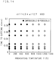
- FIG. 14 is a graph showing the examples of the fourth test results shown in FIGS. 12 and 13
- FIG. 15 is a table showing the examples of the fifth test results obtained by using the method for producing laser-welded tubes in accordance with the invention
- FIG. 16 is a table showing the examples of the fifth test results obtained by using the method for producing laser-welded tubes in accordance with the invention
- FIG. 17 is a graph showing the examples of the fifth test results shown in FIGS. 15 and 16
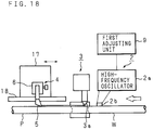
- FIG. 18 is an outline view of an apparatus for producing laser-welded tubes provided with a movable cutting tool in accordance with the invention
- FIG. 19 is an outline view of another apparatus for producing laser-welded tubes provided with a movable cutting tool in accordance with the invention
- FIGS. 20 (A), 20 (B) and 20 (C) are views showing an embodiment of a rotary bead cutting tool.
- FIG. 1 is a view showing the structure of an apparatus for producing laser-welded tubes in accordance with the invention.
- An apparatus 1 for producing laser-welded tubes has a high-frequency heating unit 2, a laser welding unit 3 and a bead cutting unit 4 arranged in the transfer direction of metal band W (in the direction of the hollow arrow shown in the figure) from the upstream side to the downstream side.
- the high-frequency heating unit 2 has a high-frequency oscillator 2a and contact tips 2b, 2b which receive high-frequency current from the oscillator 2a and supply the high-frequency current to edges W1, W1 of metal band W before welding.
- the laser welding unit 3 has a laser oscillator (not shown), a light-guiding tube (not shown) and a welding torch 3a.
- the bead cutting unit 4 has a fixed cutting tool 5 and a tool holder 6 for holding the fixed cutting tool 5.
- squeeze rolls 7, 7 are provided to control the abutting shape of edges W1, W1 of metal band W. Furthermore, on the upstream side of the production line shown in FIG. 1, a breakdown stand having a plurality of horizontal rolls for performing initial forming including the forming of the edges of metal band W, a cluster stand having a plurality of side rolls for performing the forming of the central section of metal band W and a fin-pass stand having a plurality of horizontal rolls for performing finish forming are provided in the order from the upstream side. In FIG. 1, only the horizontal roll 8 on the most downstream side of the fin-pass stand is shown and other sections are not shown.
- the high-frequency current from the high-frequency oscillator 2a of the high-frequency heating unit 2 is controlled by power adjustment at a first adjusting unit 9.
- the rotation speeds of the rolls of the above-mentioned stands are adjusted by a second adjusting unit 10.
- the second adjusting unit 10 controls the transfer speed of metal band W (welded tube P) at the production line.
- Metal band W is transferred in the direction indicated by the hollow arrow in FIG. 1 and metal band W is gradually formed into a cylindrical shape by the forming rolls provided on the breakdown stand, cluster stand and fin-pass stand. Edges W1, W1 of metal band W to be welded are then preheated by the high-frequency heating unit 2. After preheating, edges W1, W1 of metal band W are joined by the laser welding unit 3 while edges W1, W1 are set securely in the abutting condition by the squeeze rolls 7, 7 to form welded tube P. Welded tube P produced in this way is transferred to the downstream side and welding beads are cut and eliminated by the fixed cutting tool 5 of the bead cutting unit 4.
- the preheating power at the high-frequency heating unit 2 is adjusted by the first adjusting unit 9 and the transfer speed of metal band W (welding tube P) at the production line is adjusted by the second adjusting unit 10.
- edges W1, W1 of metal band W are preheated by the high-frequency heating unit 2 so that temperature T at edges W1, W1 of metal band W before laser welding satisfies the condition (2) described below.
- FIG. 2 is a graph showing the temperature drops at the welded sections in various welding methods. By setting the welding point to "0" when a test material is fed at a transfer speed of 10 m/minute, this graph shows the distance of the downstream movement from the zero welding point on the abscissa and shows the temperature at the welding center on the ordinate.
- the preheating temperature in accordance with the invention is the temperature at the edges of the metal band before laser welding.
- the temperature drop is extremely significant although the temperature at the welding center is the same, when compared with the two examples of the laser welding method of the invention with preheating conducted (indicated by lines b and c). This significant drop is the cause of the problem encountered in the conventional method, that is, the welding beads are hardened and cannot be cut.
- the outer diameter d (mm) of the test material represents the finished outer diameter of the welded tube.
- the wall thickness a (mm) of the test material represents the thickness of metal band W (the finished wall thickness of the welded tube to be produced).
- Preheating temperature T (°C) represents the temperature at edges W1, W1 of metal band W before laser welding.
- the welding speed (m/sec) represents the transfer speed of metal band W (welded tube P).
- Laser output (kW) represents the output of the laser welding unit 3.
- the cutting position (m) represents the distance from the laser welding unit 3 to the bead cutting unit 4.
- the time to cutting t (min) represents time from the start of laser welding to the cutting of welding beads (the time for transferring welded tube P from the laser welding unit 3 to the bead cutting unit 4).
- the possibility of cutting represents whether the cutting of the welding beads can be done actually ( ⁇ ) or not (X) at the bead cutting unit 4.
- the conformity to condition represents whether the above-mentioned condition (2) can be satisfied ( ⁇ ) or not (X).
- Each test result includes a test result obtained by simulation.
- the graphs in FIGS. 5, 8, 11, 14 and 17 are respectively based on the test results shown in FIGS. 3 and 4, FIGS. 6 and 7, FIGS. 9 and 10, FIGS. 12 and 13, and FIGS. 15 and 16, and show whether cutting is possible or not ( ⁇ : possible, ⁇ : impossible) with the abscissa used to represent preheating temperature T and the ordinate used to represent time to cutting t.
- the results of the first test example are shown in FIGS. 3, 4 and 5. The conditions of the first test example are described below.
- FIG. 18 shows the structure of the embodiment.
- a bead cutting unit 4 having a fixed cutting tool 5 and a tool holder 6 for holding the cutting tool is mounted on a slider 17.
- the slider 17 is movable reciprocally along a horizontal bed 18 in the direction of the production line. Parts similar to those described in FIG. 1 are denoted by the same reference numbers and the descriptions for these parts are omitted.
- Metal band W is transferred in the direction indicated by the hollow arrow in the figure and subjected to preheating by a high-frequency heating unit 2, laser welding by a laser welding unit 3 and cutting by the bead cutting unit 4 in the same way as described in FIG. 1 to produce a welded tube P.
- the bead cutting unit 4 (fixed cutting tool 5) is movable in parallel with the transfer line as shown by arrows in the figure.
- the cutting of the welding beads can be done while the time from the start of laser welding to the cutting of the welded beads is shortened substantially by moving the slider 17, on which the bead cutting unit 4 (fixed cutting tool 5) is mounted, toward the laser welding unit 3.
- FIG. 19 shows a structure of an apparatus for producing laser-welded tubes in accordance with another embodiment of the invention provided with a movable cutting tool.
- a fixed cutting tool 5 is set at the tip of a mandrel 21 which is inserted movably in the longitudinal direction inside tube-shaped metal band W.
- This embodiment produces the same effect as the embodiment shown in FIG. 18.
- the depth of cut of the fixed cutting tool 5 can be adjusted by rocking a roll 22 vertically around the fulcrum thereof.
- FIGS. 20 (A) to (C) show an embodiment of a rotary bead cutting tool.
- a rotary cutting tool 30 has a housing 31, a bearing 32 and a ring cutter 33.
- the ring cutter 33 is set in a condition inclined by angle ⁇ from the line perpendicular to the axis of tube-shaped metal band W as viewed in a single plane.
- the ring cutter 33 is rotated on its own axis by a component of the force.
- the ring cutter 33 cuts the outer surface of the welding bead as shown in FIG. 20 (B).
- laser welding is performed after the edges of a metal band to be welded are preheated to form a tube.
- the welding beads generated on the outer and/or inner surfaces of the welded section are cut and eliminated immediately after welding by using a cutting tool. Preheating before welding restrains the welded section from quick cooling and prevents the welding beads from hardening quickly.
- the welding beads can be cut and the finished dimensions of the welded tube can have higher accuracy.
- the welding speed can be raised as the laser output during laser welding is larger, the selection ranges of the cutting position and preheating temperature can be extended significantly.
- the cutting tool is set movable in the method for producing laser-welded tubes in accordance with the invention, the time from the start of laser welding to the cutting of the welding beads can be changed. For this reason, when the line speed is low for example, the welding beads can be cut by moving the cutting tool toward the welding position.
Landscapes
- Engineering & Computer Science (AREA)
- Mechanical Engineering (AREA)
- Physics & Mathematics (AREA)
- Optics & Photonics (AREA)
- Plasma & Fusion (AREA)
- Laser Beam Processing (AREA)
Applications Claiming Priority (4)
| Application Number | Priority Date | Filing Date | Title |
|---|---|---|---|
| JP175021/94 | 1994-07-27 | ||
| JP17502194 | 1994-07-27 | ||
| JP17502194 | 1994-07-27 | ||
| PCT/JP1995/001464 WO1996003249A1 (en) | 1994-07-27 | 1995-07-21 | Method of manufacturing laser welded pipes and apparatus for manufacturing the same |
Publications (3)
| Publication Number | Publication Date |
|---|---|
| EP0721818A1 true EP0721818A1 (de) | 1996-07-17 |
| EP0721818A4 EP0721818A4 (de) | 1997-12-17 |
| EP0721818B1 EP0721818B1 (de) | 2000-03-15 |
Family
ID=15988836
Family Applications (1)
| Application Number | Title | Priority Date | Filing Date |
|---|---|---|---|
| EP95926013A Expired - Lifetime EP0721818B1 (de) | 1994-07-27 | 1995-07-21 | Verfahren und vorrichtung zur herstellung von laser-geschweissten röhren |
Country Status (5)
| Country | Link |
|---|---|
| EP (1) | EP0721818B1 (de) |
| KR (1) | KR100265699B1 (de) |
| CA (1) | CA2170055A1 (de) |
| DE (1) | DE69515628T2 (de) |
| WO (1) | WO1996003249A1 (de) |
Cited By (5)
| Publication number | Priority date | Publication date | Assignee | Title |
|---|---|---|---|---|
| WO1998010884A1 (de) * | 1996-09-13 | 1998-03-19 | Fraunhofer-Gesellschaft zur Förderung der angewandten Forschung e.V. | Verfahren zum strahlschweissen von härtbaren stählen mittels kurzzeitwärmebehandlung |
| WO1998025727A1 (fr) * | 1996-12-10 | 1998-06-18 | Obschestvo S Ogranichennoi Otvetstvennostju 'lastr' | Procede de fabrication de tubes a soudure longitudinale par soudage laser et dispositif prevu a cet effet |
| EP0842716A3 (de) * | 1996-11-16 | 2000-10-11 | Alcatel | Verfahren und Vorrichtung zur Herstellung von Metallröhrchen grosser Länge |
| WO2001007194A1 (de) * | 1999-07-23 | 2001-02-01 | Linde Aktiengesellschaft | Verfahren und vorrichtung zum schweissen mit kompensation des schweissverzugs |
| CN102821905A (zh) * | 2010-03-30 | 2012-12-12 | 锂电池科技有限公司 | 用于伽伐尼电池的导体的接触元件 |
Families Citing this family (3)
| Publication number | Priority date | Publication date | Assignee | Title |
|---|---|---|---|---|
| ATE199332T1 (de) * | 1996-06-11 | 2001-03-15 | Kawasaki Steel Co | Verfahren und vorrichtung zur herstellung von stahlrohren |
| KR101444849B1 (ko) * | 2010-01-07 | 2014-09-29 | 삼성테크윈 주식회사 | 회전 기계의 회전부 제조 방법 |
| CN113631319B (zh) * | 2019-03-27 | 2024-02-27 | 株式会社博迈立铖 | 焊接管的制造方法及焊接管的制造装置 |
Family Cites Families (4)
| Publication number | Priority date | Publication date | Assignee | Title |
|---|---|---|---|---|
| JPS61270339A (ja) * | 1985-05-27 | 1986-11-29 | Kobe Steel Ltd | 耐溝食性に優れた溶接管の製造方法 |
| US5140123A (en) * | 1990-05-25 | 1992-08-18 | Kusakabe Electric & Machinery Co., Ltd. | Continuous manufacturing method for a metal welded tube and a manufacturing apparatus therefor |
| JPH04258390A (ja) * | 1991-02-07 | 1992-09-14 | Sumitomo Metal Ind Ltd | フェライト系ステンレス鋼溶接管の製造方法 |
| JP2650558B2 (ja) * | 1992-03-30 | 1997-09-03 | 住友金属工業株式会社 | 高加工性溶接鋼管の製造方法 |
-
1995
- 1995-07-21 EP EP95926013A patent/EP0721818B1/de not_active Expired - Lifetime
- 1995-07-21 KR KR1019950704256A patent/KR100265699B1/ko not_active Expired - Fee Related
- 1995-07-21 CA CA002170055A patent/CA2170055A1/en not_active Abandoned
- 1995-07-21 DE DE69515628T patent/DE69515628T2/de not_active Expired - Fee Related
- 1995-07-21 WO PCT/JP1995/001464 patent/WO1996003249A1/ja not_active Ceased
Cited By (6)
| Publication number | Priority date | Publication date | Assignee | Title |
|---|---|---|---|---|
| WO1998010884A1 (de) * | 1996-09-13 | 1998-03-19 | Fraunhofer-Gesellschaft zur Förderung der angewandten Forschung e.V. | Verfahren zum strahlschweissen von härtbaren stählen mittels kurzzeitwärmebehandlung |
| US6365866B1 (en) | 1996-09-13 | 2002-04-02 | Fraunhofer-Gesellschaft zur Föderung der angewandten Forschung e.V. | Method for beam welding of hardenable steels by means of short-time heat treatment |
| EP0842716A3 (de) * | 1996-11-16 | 2000-10-11 | Alcatel | Verfahren und Vorrichtung zur Herstellung von Metallröhrchen grosser Länge |
| WO1998025727A1 (fr) * | 1996-12-10 | 1998-06-18 | Obschestvo S Ogranichennoi Otvetstvennostju 'lastr' | Procede de fabrication de tubes a soudure longitudinale par soudage laser et dispositif prevu a cet effet |
| WO2001007194A1 (de) * | 1999-07-23 | 2001-02-01 | Linde Aktiengesellschaft | Verfahren und vorrichtung zum schweissen mit kompensation des schweissverzugs |
| CN102821905A (zh) * | 2010-03-30 | 2012-12-12 | 锂电池科技有限公司 | 用于伽伐尼电池的导体的接触元件 |
Also Published As
| Publication number | Publication date |
|---|---|
| DE69515628T2 (de) | 2000-11-02 |
| CA2170055A1 (en) | 1996-02-08 |
| DE69515628D1 (de) | 2000-04-20 |
| EP0721818A4 (de) | 1997-12-17 |
| KR100265699B1 (ko) | 2000-09-15 |
| KR960702359A (ko) | 1996-04-27 |
| WO1996003249A1 (en) | 1996-02-08 |
| EP0721818B1 (de) | 2000-03-15 |
Similar Documents
| Publication | Publication Date | Title |
|---|---|---|
| US5968380A (en) | Method for producing laser-welded tubes and apparatus for producing the same | |
| EP0880423B1 (de) | Stanzmesser und herstellungsverfahren | |
| EP0933159B1 (de) | Herstellungsverfahren eines geschweissten Stahlrohres | |
| JPS58119481A (ja) | レ−ザ溶接方法 | |
| EP0721818B1 (de) | Verfahren und vorrichtung zur herstellung von laser-geschweissten röhren | |
| JPS6293028A (ja) | レ−ザによる板材の曲げ加工方法 | |
| WO1997029878A1 (en) | Cutting die and method of making | |
| JP2861836B2 (ja) | フェライト系ステンレス鋼のレーザ溶接方法 | |
| JPH0857642A (ja) | 溶接鋼管の製造方法 | |
| JPS6156746A (ja) | 継目無鋼管の拡管加工法 | |
| CN113631319A (zh) | 焊接管的制造方法及焊接管的制造装置 | |
| JPWO1996003249A1 (ja) | レーザ溶接管の製造方法及びその製造装置 | |
| WO2023153018A1 (ja) | レーザビーム溶接方法とその溶接機ならびに突合せ溶接継手 | |
| JP2001287061A (ja) | マルテンサイト系ステンレス溶接鋼管の製造方法 | |
| JP2867790B2 (ja) | フィンパスロール及び溶接管製造装置 | |
| US4376882A (en) | Method of resistance flash butt welding | |
| JPH0924480A (ja) | 溶接鋼管の製造方法 | |
| JPS6156792A (ja) | 極薄肉溶接管の製造方法 | |
| RU2804202C1 (ru) | Способ механической обработки стальной заготовки аустенитного класса с дроблением стружки | |
| US3944775A (en) | Welding process | |
| JPH08285030A (ja) | ボールネジおよびその製造方法 | |
| JPH0515986A (ja) | レーザーによる製管溶接方法 | |
| JP2924675B2 (ja) | 溶接形鋼の製造方法 | |
| JPH03114685A (ja) | 金属帯のレーザ溶接に供せられる突き合わせ開先の形成方法 | |
| JPS58165913A (ja) | 電縫管の溶接ビ−ド切削方法 |
Legal Events
| Date | Code | Title | Description |
|---|---|---|---|
| PUAI | Public reference made under article 153(3) epc to a published international application that has entered the european phase |
Free format text: ORIGINAL CODE: 0009012 |
|
| 17P | Request for examination filed |
Effective date: 19950926 |
|
| AK | Designated contracting states |
Kind code of ref document: A1 Designated state(s): DE FR GB IT |
|
| A4 | Supplementary search report drawn up and despatched |
Effective date: 19971029 |
|
| AK | Designated contracting states |
Kind code of ref document: A4 Designated state(s): DE FR GB IT |
|
| GRAG | Despatch of communication of intention to grant |
Free format text: ORIGINAL CODE: EPIDOS AGRA |
|
| 17Q | First examination report despatched |
Effective date: 19990521 |
|
| GRAG | Despatch of communication of intention to grant |
Free format text: ORIGINAL CODE: EPIDOS AGRA |
|
| GRAH | Despatch of communication of intention to grant a patent |
Free format text: ORIGINAL CODE: EPIDOS IGRA |
|
| GRAH | Despatch of communication of intention to grant a patent |
Free format text: ORIGINAL CODE: EPIDOS IGRA |
|
| GRAA | (expected) grant |
Free format text: ORIGINAL CODE: 0009210 |
|
| AK | Designated contracting states |
Kind code of ref document: B1 Designated state(s): DE FR GB IT |
|
| REF | Corresponds to: |
Ref document number: 69515628 Country of ref document: DE Date of ref document: 20000420 |
|
| ET | Fr: translation filed | ||
| ITF | It: translation for a ep patent filed | ||
| PLBE | No opposition filed within time limit |
Free format text: ORIGINAL CODE: 0009261 |
|
| STAA | Information on the status of an ep patent application or granted ep patent |
Free format text: STATUS: NO OPPOSITION FILED WITHIN TIME LIMIT |
|
| 26N | No opposition filed | ||
| REG | Reference to a national code |
Ref country code: GB Ref legal event code: IF02 |
|
| PGFP | Annual fee paid to national office [announced via postgrant information from national office to epo] |
Ref country code: FR Payment date: 20030711 Year of fee payment: 9 |
|
| PGFP | Annual fee paid to national office [announced via postgrant information from national office to epo] |
Ref country code: GB Payment date: 20030716 Year of fee payment: 9 |
|
| PGFP | Annual fee paid to national office [announced via postgrant information from national office to epo] |
Ref country code: DE Payment date: 20030731 Year of fee payment: 9 |
|
| PG25 | Lapsed in a contracting state [announced via postgrant information from national office to epo] |
Ref country code: GB Free format text: LAPSE BECAUSE OF NON-PAYMENT OF DUE FEES Effective date: 20040721 |
|
| PG25 | Lapsed in a contracting state [announced via postgrant information from national office to epo] |
Ref country code: DE Free format text: LAPSE BECAUSE OF NON-PAYMENT OF DUE FEES Effective date: 20050201 |
|
| GBPC | Gb: european patent ceased through non-payment of renewal fee |
Effective date: 20040721 |
|
| PG25 | Lapsed in a contracting state [announced via postgrant information from national office to epo] |
Ref country code: FR Free format text: LAPSE BECAUSE OF NON-PAYMENT OF DUE FEES Effective date: 20050331 |
|
| REG | Reference to a national code |
Ref country code: FR Ref legal event code: ST |
|
| PG25 | Lapsed in a contracting state [announced via postgrant information from national office to epo] |
Ref country code: IT Free format text: LAPSE BECAUSE OF NON-PAYMENT OF DUE FEES Effective date: 20050721 |