EP0721841A2 - Flüssigkeitsausstosskopf, Vorrichtung zum Ausstossen von Flüssigkeit und Verfahren zum Ausstossen von Flüssigkeit - Google Patents
Flüssigkeitsausstosskopf, Vorrichtung zum Ausstossen von Flüssigkeit und Verfahren zum Ausstossen von Flüssigkeit Download PDFInfo
- Publication number
- EP0721841A2 EP0721841A2 EP96300242A EP96300242A EP0721841A2 EP 0721841 A2 EP0721841 A2 EP 0721841A2 EP 96300242 A EP96300242 A EP 96300242A EP 96300242 A EP96300242 A EP 96300242A EP 0721841 A2 EP0721841 A2 EP 0721841A2
- Authority
- EP
- European Patent Office
- Prior art keywords
- liquid
- bubble
- movable member
- flow path
- free end
- Prior art date
- Legal status (The legal status is an assumption and is not a legal conclusion. Google has not performed a legal analysis and makes no representation as to the accuracy of the status listed.)
- Granted
Links
Images


Classifications
-
- B—PERFORMING OPERATIONS; TRANSPORTING
- B41—PRINTING; LINING MACHINES; TYPEWRITERS; STAMPS
- B41J—TYPEWRITERS; SELECTIVE PRINTING MECHANISMS, i.e. MECHANISMS PRINTING OTHERWISE THAN FROM A FORME; CORRECTION OF TYPOGRAPHICAL ERRORS
- B41J2/00—Typewriters or selective printing mechanisms characterised by the printing or marking process for which they are designed
- B41J2/005—Typewriters or selective printing mechanisms characterised by the printing or marking process for which they are designed characterised by bringing liquid or particles selectively into contact with a printing material
- B41J2/01—Ink jet
- B41J2/015—Ink jet characterised by the jet generation process
-
- B—PERFORMING OPERATIONS; TRANSPORTING
- B41—PRINTING; LINING MACHINES; TYPEWRITERS; STAMPS
- B41J—TYPEWRITERS; SELECTIVE PRINTING MECHANISMS, i.e. MECHANISMS PRINTING OTHERWISE THAN FROM A FORME; CORRECTION OF TYPOGRAPHICAL ERRORS
- B41J2/00—Typewriters or selective printing mechanisms characterised by the printing or marking process for which they are designed
- B41J2/005—Typewriters or selective printing mechanisms characterised by the printing or marking process for which they are designed characterised by bringing liquid or particles selectively into contact with a printing material
- B41J2/01—Ink jet
- B41J2/135—Nozzles
- B41J2/14—Structure thereof only for on-demand ink jet heads
- B41J2/14016—Structure of bubble jet print heads
- B41J2/14032—Structure of the pressure chamber
- B41J2/14048—Movable member in the chamber
-
- B—PERFORMING OPERATIONS; TRANSPORTING
- B41—PRINTING; LINING MACHINES; TYPEWRITERS; STAMPS
- B41J—TYPEWRITERS; SELECTIVE PRINTING MECHANISMS, i.e. MECHANISMS PRINTING OTHERWISE THAN FROM A FORME; CORRECTION OF TYPOGRAPHICAL ERRORS
- B41J2/00—Typewriters or selective printing mechanisms characterised by the printing or marking process for which they are designed
- B41J2/005—Typewriters or selective printing mechanisms characterised by the printing or marking process for which they are designed characterised by bringing liquid or particles selectively into contact with a printing material
- B41J2/01—Ink jet
- B41J2/135—Nozzles
- B41J2/14—Structure thereof only for on-demand ink jet heads
- B41J2/14016—Structure of bubble jet print heads
- B41J2/14024—Assembling head parts
-
- B—PERFORMING OPERATIONS; TRANSPORTING
- B41—PRINTING; LINING MACHINES; TYPEWRITERS; STAMPS
- B41J—TYPEWRITERS; SELECTIVE PRINTING MECHANISMS, i.e. MECHANISMS PRINTING OTHERWISE THAN FROM A FORME; CORRECTION OF TYPOGRAPHICAL ERRORS
- B41J2/00—Typewriters or selective printing mechanisms characterised by the printing or marking process for which they are designed
- B41J2/005—Typewriters or selective printing mechanisms characterised by the printing or marking process for which they are designed characterised by bringing liquid or particles selectively into contact with a printing material
- B41J2/01—Ink jet
- B41J2/135—Nozzles
- B41J2/14—Structure thereof only for on-demand ink jet heads
- B41J2/14016—Structure of bubble jet print heads
- B41J2/14032—Structure of the pressure chamber
- B41J2/1404—Geometrical characteristics
-
- B—PERFORMING OPERATIONS; TRANSPORTING
- B41—PRINTING; LINING MACHINES; TYPEWRITERS; STAMPS
- B41J—TYPEWRITERS; SELECTIVE PRINTING MECHANISMS, i.e. MECHANISMS PRINTING OTHERWISE THAN FROM A FORME; CORRECTION OF TYPOGRAPHICAL ERRORS
- B41J2/00—Typewriters or selective printing mechanisms characterised by the printing or marking process for which they are designed
- B41J2/005—Typewriters or selective printing mechanisms characterised by the printing or marking process for which they are designed characterised by bringing liquid or particles selectively into contact with a printing material
- B41J2/01—Ink jet
- B41J2/135—Nozzles
- B41J2/14—Structure thereof only for on-demand ink jet heads
- B41J2002/14362—Assembling elements of heads
-
- B—PERFORMING OPERATIONS; TRANSPORTING
- B41—PRINTING; LINING MACHINES; TYPEWRITERS; STAMPS
- B41J—TYPEWRITERS; SELECTIVE PRINTING MECHANISMS, i.e. MECHANISMS PRINTING OTHERWISE THAN FROM A FORME; CORRECTION OF TYPOGRAPHICAL ERRORS
- B41J2/00—Typewriters or selective printing mechanisms characterised by the printing or marking process for which they are designed
- B41J2/005—Typewriters or selective printing mechanisms characterised by the printing or marking process for which they are designed characterised by bringing liquid or particles selectively into contact with a printing material
- B41J2/01—Ink jet
- B41J2/135—Nozzles
- B41J2/14—Structure thereof only for on-demand ink jet heads
- B41J2002/14379—Edge shooter
-
- B—PERFORMING OPERATIONS; TRANSPORTING
- B41—PRINTING; LINING MACHINES; TYPEWRITERS; STAMPS
- B41J—TYPEWRITERS; SELECTIVE PRINTING MECHANISMS, i.e. MECHANISMS PRINTING OTHERWISE THAN FROM A FORME; CORRECTION OF TYPOGRAPHICAL ERRORS
- B41J2202/00—Embodiments of or processes related to ink-jet or thermal heads
- B41J2202/01—Embodiments of or processes related to ink-jet heads
- B41J2202/21—Line printing
Definitions
- a head cartridge comprising: a liquid ejecting head as defined above; and a liquid container for containing the liquid to be supplied to the liquid ejecting head.
- a liquid ejecting apparatus for ejecting recording liquid by generation of a bubble. comprising: a liquid ejecting head as defined above; and driving signal supply means for supplying a driving signal for ejecting the liquid through the liquid ejecting head.
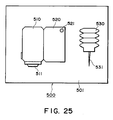
- a head kit comprising: a liquid ejecting head as defined above: a liquid container for containing the liquid to be supplied to the liquid ejecting head; and liquid filling means for filling the liquid into the liquid container.
- upstream and downstream are defined with respect to a general liquid flow from a liquid supply source to the ejection outlet through the bubble generation region (movable member).
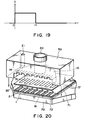
- Fig. 20 is an exploded perspective view of the liquid ejection head in accordance with the present invention.
- Fig. 21 is an exploded perspective view of a liquid ejection head cartridge.
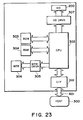
- Fig. 22 is a perspective view of a liquid ejection apparatus, depicting the general structure thereof.
- Fig. 23 is a block diagram of the apparatus illustrated in Fig. 22.
- Fig. 24 is a perspective view of a liquid ejection recording system.
- Fig. 25 is a schematic drawing of a head kit.
- the liquid ejecting head of this embodiment comprises a heat generating element 2 (a heat generating resistor of 40 ⁇ m x 105 ⁇ m in this embodiment) as the ejection energy generating element for supplying thermal energy to the liquid to eject the liquid, an element substrate 1 on which said heat generating element 2 is provided, and a liquid flow path 10 formed above the element substrate correspondingly to the heat generating element 2.
- the liquid flow path 10 is in fluid communication with a common liquid chamber 13 for supplying the liquid to a plurality of such liquid flow paths 10 which is in fluid communication with a plurality of the ejection outlets 18.
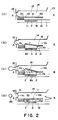
- the movable member disposed faced to the bubble is displaced from the normal first position to the displaced second position on the basis of the pressure of the bubble generation or the bubble per se, and the displacing or displaced movable member 31 is effective to direct the pressure produced by the generation of the bubble and/or the growth of the bubble per se toward the ejection outlet 18 (downstream side).
- the bubble 40 is controlled so that it grows in the direction in which the pressure generated by the bubble 40 can easily escape or be released, and in which the bubble 40 easily shifts in volumetric terms. In other words, the growth of the bubble is uniformly directed toward the free end of the movable member. This also is thought to contribute to the improvement of the ejection efficiency.
- the movable member 31 having been displaced to the second position returns to the initial position (first position) of Figure 2, (a) by the restoring force provided by the spring property of the movable member per se and the negative pressure due to the contraction of the bubble.
- the liquid flows back from the common liquid chamber side as indicated by V D1 and V D2 and from the ejection outlet side as indicated by V C so as to compensate for the volume reduction of the bubble in the bubble generation region 11 and to compensate for the volume of the ejected liquid.
- the number of the common liquid chambers may be one.
- first and second liquid flow paths there is a separation wall 30 of an elastic material such as metal so that the first flow path and the second flow path are separated.
- the first liquid flow path 14 and the second liquid flow path 16 are preferably isolated by the partition wall. however, when the mixing to a certain extent is permissible, the complete isolation is not inevitable.
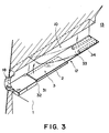
- a partition wall 30 is disposed, with a space for constituting a second liquid flow path, above an element substrate 1 provided with a heat generating resistor portion as the heat generating element 2 and wiring electrodes (not shown) for applying an electric signal to the heat generating resistor portion.
- the configuration of the first liquid passage 16 is such that its resistance against the motion of the member is smaller near the free end 32 of the movable member 31 than near the supporting portion 33 of the movable member 31.
- the structure in accordance with the present invention can further improve the uniformity in the ejection characteristic among the plural liquid passages.
- the present invention may be applied only to these specific regions.
- the employment of the structure in accordance with the present invention can also stabilize the ejection characteristic.
- the flow resistance is reduced on the free end side compared to that on the supporting portion side, by modifying the ceiling structure of the first liquid passage.
- it may be reduced by other means such as modifying the structures of the lateral walls of the first liquid passage; for example, the portion with lower flow resistance may be created by making the liquid passage width greater than the movable member width, and the portion with higher flow resistance may be created by making the liquid passage width less than the movable member width.
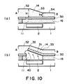
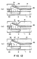
- Figure 10 is a schematic section of the essential portion of the liquid ejection head which offers the same effects as the preceding embodiment, and depicts the specific liquid passage structure thereof.
- the structure in this embodiment is basically the same as that illustrated in Figure 8.
- a ceiling height h1 on the free end side of the movable member 31 is greater than a ceiling height h2 on the supporting portion side of the movable member 31, and the ceiling section between the high and low sections forms a straight slope.
- an engagement portion 57 is provided, which regulates the upward movement of the movable member 31 by coming in contact with the free end portion 32 of the movable member 31 as the movable member 31 is moved.
- the provision of this engagement portion 57 assures more reliable regulation of the free end portion 32, further improving the durability of the movable member.
- the durability of the movable member can be drastically improved.
- the movable member displays relatively small rigidity, it can be prevented from being excessively flexed: therefore, the bubble is prevented from growing in directions (toward ceiling, or in the upstream direction) different from the direction of the ejection orifice, and also, the pressure from the bubble is prevented from being transmitted in directions other than the direction of the ejection orifice. As a result, it is possible to prevent the loss of ejection efficiency.
- metal material such as tantalum (Ta) or the like is used as the anti-cavitation layer.
- the aforementioned element substrate 1 is disposed on a supporting member 70 of aluminum or the like.
- the wall 72 of the second liquid passage and the wall 71 of the second common liquid chamber 17 are disposed on this substrate 1.
- the partition wall 30, a part of which constitutes a moving member 31, is placed on top of them.
- a grooved member 50 is disposed, which comprises: plural grooves constituting first liquid passages 14; a first common liquid chamber 15; a supply passage 20 for supplying the first common liquid chamber 15 with first liquid; and a supply passage 21 for supplying the second common liquid chamber 17 with second liquid.
- Figure 21 is a schematic exploded perspective view of a liquid ejection head cartridge including the above-described liquid ejecting head, and the liquid ejection head cartridge comprises generally a liquid ejecting head portion 200 and a liquid container 80.
Landscapes
- Physics & Mathematics (AREA)
- Geometry (AREA)
- Particle Formation And Scattering Control In Inkjet Printers (AREA)
- Ink Jet (AREA)
- Application Of Or Painting With Fluid Materials (AREA)
- Nozzles (AREA)
- Ink Jet Recording Methods And Recording Media Thereof (AREA)
Priority Applications (1)
| Application Number | Priority Date | Filing Date | Title |
|---|---|---|---|
| EP02079443A EP1281521B1 (de) | 1995-01-13 | 1996-01-12 | Flüssigkeitsausstosskopf, und Flüssigkeitsausstossverfahren |
Applications Claiming Priority (6)
| Application Number | Priority Date | Filing Date | Title |
|---|---|---|---|
| JP410995 | 1995-01-13 | ||
| JP410995 | 1995-01-13 | ||
| JP4109/95 | 1995-01-13 | ||
| JP12844895 | 1995-05-26 | ||
| JP12844895 | 1995-05-26 | ||
| JP128448/95 | 1995-05-26 |
Related Child Applications (1)
| Application Number | Title | Priority Date | Filing Date |
|---|---|---|---|
| EP02079443A Division EP1281521B1 (de) | 1995-01-13 | 1996-01-12 | Flüssigkeitsausstosskopf, und Flüssigkeitsausstossverfahren |
Publications (3)
| Publication Number | Publication Date |
|---|---|
| EP0721841A2 true EP0721841A2 (de) | 1996-07-17 |
| EP0721841A3 EP0721841A3 (de) | 1997-04-16 |
| EP0721841B1 EP0721841B1 (de) | 2003-05-14 |
Family
ID=26337827
Family Applications (2)
| Application Number | Title | Priority Date | Filing Date |
|---|---|---|---|
| EP96300242A Expired - Lifetime EP0721841B1 (de) | 1995-01-13 | 1996-01-12 | Flüssigkeitsausstosskopf, Vorrichtung zum Ausstossen von Flüssigkeit und Verfahren zum Ausstossen von Flüssigkeit |
| EP02079443A Expired - Lifetime EP1281521B1 (de) | 1995-01-13 | 1996-01-12 | Flüssigkeitsausstosskopf, und Flüssigkeitsausstossverfahren |
Family Applications After (1)
| Application Number | Title | Priority Date | Filing Date |
|---|---|---|---|
| EP02079443A Expired - Lifetime EP1281521B1 (de) | 1995-01-13 | 1996-01-12 | Flüssigkeitsausstosskopf, und Flüssigkeitsausstossverfahren |
Country Status (10)
| Country | Link |
|---|---|
| US (2) | US6334669B1 (de) |
| EP (2) | EP0721841B1 (de) |
| KR (1) | KR100197927B1 (de) |
| CN (1) | CN1070111C (de) |
| AT (2) | ATE240209T1 (de) |
| AU (1) | AU4092296A (de) |
| CA (1) | CA2167143C (de) |
| DE (2) | DE69628062T2 (de) |
| SG (1) | SG42312A1 (de) |
| TW (1) | TW312658B (de) |
Cited By (31)
| Publication number | Priority date | Publication date | Assignee | Title |
|---|---|---|---|---|
| EP0811495A3 (de) * | 1996-06-07 | 1998-08-19 | Canon Kabushiki Kaisha | Flüssigkeitsausstosskopf, Kopfkassette und Vorrichtung zum Ausstossen von Flüssigkeit |
| EP0818316A3 (de) * | 1996-07-01 | 1998-09-30 | Canon Kabushiki Kaisha | Kassette als Flüssigkeitsstrahlkopf und zugehöriger Flüssigkeitsbehälter |
| EP0819532A3 (de) * | 1996-07-12 | 1998-11-04 | Canon Kabushiki Kaisha | Flüssigkeitsausstosskopf, Wiederherstellungsverfahren und Herstellungsverfahren für einen Flüssigkeitsausstosskopf und diesen Kopf verwendende Flüssigkeitsausstossvorrichtung |
| EP0818314A3 (de) * | 1996-07-12 | 1999-02-10 | Canon Kabushiki Kaisha | Flüssigkeitsbehälter, Kopfpatrone, Flüssigkeitsausstossgerät und Steuerverfahren |
| EP0920998A3 (de) * | 1997-12-05 | 2000-07-05 | Canon Kabushiki Kaisha | Flüssigkeitsausstosskopf, Flüssigkeitsausstossverfahren, Kopfkassette und Flüssigkeitsausstossvorrichtung |
| EP0920996A3 (de) * | 1997-12-05 | 2000-07-05 | Canon Kabushiki Kaisha | Flüssigkeitsausstosskopf, Herstellungsverfahren des Flüssigkeitsausstosskopfes, Kassette mit diesem Flüssigkeitsausstosskopf und Flüssigkeitsausstossvorrichtung |
| EP0982136A3 (de) * | 1998-08-21 | 2000-08-30 | Canon Kabushiki Kaisha | Flüssigkeitsausstosskopf, Flüssigkeitsausstossverfahren und Flüssigkeitsausstossvorrichtung |
| EP0976562A3 (de) * | 1998-07-28 | 2000-08-30 | Canon Kabushiki Kaisha | Flüssigkeitsausstosskopf und Flüssigkeitsausstossverfahren |
| EP0976561A3 (de) * | 1998-07-28 | 2000-09-06 | Canon Kabushiki Kaisha | Flüssigkeitsausstosskopf, Flüssigkeitsausstossverfahren und Flüssigkeitsausstossvorrichtung |
| EP1005991A3 (de) * | 1998-12-03 | 2000-11-22 | Canon Kabushiki Kaisha | Flüssigkeitsausstosskopf, Verfahren zur Herstellung und Flüssigkeitsausstossapparat |
| EP1072413A3 (de) * | 1999-07-27 | 2001-04-18 | Canon Kabushiki Kaisha | Verfahren zum Ausstossen von Flüssigkeit, Flüssigkeitsausstosskopf, Flüssigkeitsausstossgerät das einen solchen Flüssigkeitsausstosskopf verwendet |
| EP1072415A3 (de) * | 1999-07-27 | 2001-04-18 | Canon Kabushiki Kaisha | Verfahren zum Ausstossen von Flüssigkeit, Flüssigkeitsausstosskopf und Flüssigkeitsausstossgerät |
| EP1072414A3 (de) * | 1999-07-27 | 2001-04-18 | Canon Kabushiki Kaisha | Flüssigkeitsausstosskopf, Kopfkassette und Flüssigkeitsausstossgerät |
| US6357865B1 (en) * | 1998-10-15 | 2002-03-19 | Xerox Corporation | Micro-electro-mechanical fluid ejector and method of operating same |
| EP1080906A3 (de) * | 1999-09-03 | 2002-04-24 | Canon Kabushiki Kaisha | Flüssigkeitsausstosskopf, Flüssigkeitsausstossverfahren, und Flüssigkeitsausstossvorrichtung |
| US6390604B2 (en) | 1996-06-07 | 2002-05-21 | Canon Kabushiki Kaisha | Liquid discharge method and apparatus employing a movable inelastic separation film |
| US6409296B1 (en) * | 1999-07-27 | 2002-06-25 | Canon Kabushiki Kaisha | Liquid discharge method, liquid discharge head and liquid discharge apparatus |
| EP1186412A3 (de) * | 2000-07-31 | 2002-08-28 | Canon Kabushiki Kaisha | Flüssigkeitsausstosskopf und Flüssigkeitsausstossgerät |
| US6474792B2 (en) | 2000-07-31 | 2002-11-05 | Canon Kabushiki Kaisha | Liquid discharge head, method for manufacturing liquid discharge head, head cartridge on which liquid discharge head is mounted, and liquid discharge apparatus |
| CN1093794C (zh) * | 1996-07-12 | 2002-11-06 | 佳能株式会社 | 喷液头、利用此喷液头的喷液头盒以及喷液装置 |
| US6491834B1 (en) * | 1998-12-03 | 2002-12-10 | Canon Kabushiki Kaisha | Method for manufacturing liquid discharge head, liquid discharge head, head cartridge, and liquid discharge recording apparatus |
| US6505915B2 (en) | 1995-09-22 | 2003-01-14 | Canon Kabushiki Kaisha | Liquid ejection head, apparatus and recovery method for them |
| US6513914B2 (en) | 2000-07-31 | 2003-02-04 | Canon Kabushiki Kaisha | Liquid discharging head, method for manufacturing liquid discharging head, and liquid discharging apparatus |
| US6521137B2 (en) | 2000-02-15 | 2003-02-18 | Canon Kabushiki Kaisha | Method for manufacturing liquid discharge head |
| US6637867B2 (en) * | 1998-09-14 | 2003-10-28 | Canon Kabushiki Kaisha | Liquid discharge head, head cartridge provided with such head, liquid discharge apparatus and method for discharging liquid |
| US6663237B2 (en) * | 2000-09-04 | 2003-12-16 | Canon Kabushiki Kaisha | Ink jet recording method, recording unit and ink jet recording apparatus |
| AU774899B2 (en) * | 1996-06-07 | 2004-07-15 | Canon Kabushiki Kaisha | Liquid discharging head, head cartridge and liquid discharging apparatus |
| EP0819537B1 (de) * | 1996-07-09 | 2005-04-06 | Canon Kabushiki Kaisha | Flüssigkeitsausstosskopf, Flüssigkeitsausstosskopfkassette, Vorrichtung zum Ausstossen von Flüssigkeit, Drucksystem und Kit für einen Flüssigkeitsausstosskopf |
| AU2003271389B2 (en) * | 1998-08-21 | 2005-07-07 | Canon Kabushiki Kaisha | Liquid Discharge Head, Liquid Discharge Method and Liquid Discharge Apparatus |
| AU2003268873B2 (en) * | 1998-07-28 | 2006-03-16 | Canon Kabushiki Kaisha | Liquid Discharge Head, Liquid Discharge Method, and Liquid Discharge Apparatus |
| CN1322978C (zh) * | 1999-06-30 | 2007-06-27 | 西尔弗布鲁克研究股份有限公司 | 喷嘴设备 |
Families Citing this family (20)
| Publication number | Priority date | Publication date | Assignee | Title |
|---|---|---|---|---|
| TW332799B (en) | 1995-01-13 | 1998-06-01 | Canon Kk | The liquid ejecting head, device and method of liquid ejecting |
| AU4092296A (en) * | 1995-01-13 | 1996-08-08 | Canon Kabushiki Kaisha | Liquid ejecting head, liquid ejecting device and liquid ejecting method |
| US5821962A (en) * | 1995-06-02 | 1998-10-13 | Canon Kabushiki Kaisha | Liquid ejection apparatus and method |
| JP3408060B2 (ja) * | 1995-09-22 | 2003-05-19 | キヤノン株式会社 | 液体吐出方法および装置とこれらに用いられる液体吐出ヘッド |
| JPH1024584A (ja) | 1996-07-12 | 1998-01-27 | Canon Inc | 液体吐出ヘッドカートリッジおよび液体吐出装置 |
| JP3652016B2 (ja) | 1996-07-12 | 2005-05-25 | キヤノン株式会社 | 液体吐出ヘッドおよび液体吐出方法 |
| US6374482B1 (en) | 1997-08-05 | 2002-04-23 | Canon Kabushiki Kaisha | Method of manufacturing a liquid discharge head |
| US6293654B1 (en) * | 1998-04-22 | 2001-09-25 | Hewlett-Packard Company | Printhead apparatus |
| DE60029282T2 (de) | 1999-09-03 | 2007-07-05 | Canon K.K. | Flüssigkeitsausstoßkopf, Flüsigkeitsausstoßverfahren und Vorrichtung zum Ausstoßen von Flüssigkeit |
| JP3584193B2 (ja) | 2000-02-15 | 2004-11-04 | キヤノン株式会社 | 液体吐出ヘッド、液体吐出装置及び前記液体吐出ヘッドの製造方法 |
| US6431672B1 (en) * | 2001-03-01 | 2002-08-13 | Hewlett-Packard Company | Ink container having dual capillary members with differing capillary pressures for precise ink level sensing |
| US6945453B1 (en) * | 2001-08-13 | 2005-09-20 | Bank One Delaware N.A. | System and method for funding a collective account by use of an electronic tag |
| JP3826749B2 (ja) * | 2001-08-22 | 2006-09-27 | 株式会社日立製作所 | シャント抵抗を備えた電力変換装置 |
| JP2003311982A (ja) * | 2002-04-23 | 2003-11-06 | Canon Inc | 液体吐出ヘッド |
| US6755509B2 (en) * | 2002-11-23 | 2004-06-29 | Silverbrook Research Pty Ltd | Thermal ink jet printhead with suspended beam heater |
| JP6090560B2 (ja) * | 2012-10-12 | 2017-03-08 | セイコーエプソン株式会社 | 液体噴射装置 |
| JP6562694B2 (ja) | 2014-05-30 | 2019-08-21 | キヤノン株式会社 | 液体吐出ヘッド、液体吐出装置、および液体吐出ヘッドと液体収納容器の電気接続方法 |
| JP6494352B2 (ja) | 2014-05-30 | 2019-04-03 | キヤノン株式会社 | 液体吐出ヘッド |
| CN106513682B (zh) * | 2016-09-19 | 2019-02-15 | 南京钛陶智能系统有限责任公司 | 一种用于三维打印的液态原料喷射方法及其装置 |
| CN116499882B (zh) * | 2023-06-28 | 2023-09-22 | 四川省公路规划勘察设计研究院有限公司 | 一种建筑物的压力测量方法及设备 |
Family Cites Families (42)
| Publication number | Priority date | Publication date | Assignee | Title |
|---|---|---|---|---|
| CA1127227A (en) | 1977-10-03 | 1982-07-06 | Ichiro Endo | Liquid jet recording process and apparatus therefor |
| JPS5581172A (en) | 1978-12-14 | 1980-06-18 | Canon Inc | Liquid injection type recording method and device |
| US4417251A (en) | 1980-03-06 | 1983-11-22 | Canon Kabushiki Kaisha | Ink jet head |
| JPS57102366A (en) | 1980-12-18 | 1982-06-25 | Canon Inc | Ink jet head |
| US4450455A (en) | 1981-06-18 | 1984-05-22 | Canon Kabushiki Kaisha | Ink jet head |
| US4437100A (en) | 1981-06-18 | 1984-03-13 | Canon Kabushiki Kaisha | Ink-jet head and method for production thereof |
| US4558333A (en) | 1981-07-09 | 1985-12-10 | Canon Kabushiki Kaisha | Liquid jet recording head |
| US4611219A (en) | 1981-12-29 | 1986-09-09 | Canon Kabushiki Kaisha | Liquid-jetting head |
| JPS58220756A (ja) | 1982-06-18 | 1983-12-22 | Canon Inc | インクジエツト記録ヘツドの製造方法 |
| JPS58220754A (ja) | 1982-06-18 | 1983-12-22 | Canon Inc | インクジエツト記録ヘツド |
| US4609427A (en) | 1982-06-25 | 1986-09-02 | Canon Kabushiki Kaisha | Method for producing ink jet recording head |
| JPS5919168A (ja) | 1982-07-26 | 1984-01-31 | Canon Inc | インクジエツト記録ヘツド |
| US4480259A (en) | 1982-07-30 | 1984-10-30 | Hewlett-Packard Company | Ink jet printer with bubble driven flexible membrane |
| US4496960A (en) | 1982-09-20 | 1985-01-29 | Xerox Corporation | Ink jet ejector utilizing check valves to prevent air ingestion |
| US4487662A (en) * | 1982-09-20 | 1984-12-11 | Xerox Corporation | Electrodeposition method for check valve |
| JPS59123672A (ja) | 1982-12-28 | 1984-07-17 | Canon Inc | 液体噴射ヘッド及び液体噴射記録装置 |
| US4646110A (en) | 1982-12-29 | 1987-02-24 | Canon Kabushiki Kaisha | Liquid injection recording apparatus |
| JPH0616527B2 (ja) * | 1983-07-29 | 1994-03-02 | 関西日本電気株式会社 | 半導体ウエ−ハダイシング用接着シ−ト |
| JPS61110557A (ja) | 1984-11-05 | 1986-05-28 | Canon Inc | 液体噴射記録ヘツド |
| US4646120A (en) | 1985-03-21 | 1987-02-24 | The United States Of America As Represented By The Secretary Of The Army | Photodiode array |
| JPS6169467A (ja) | 1985-06-11 | 1986-04-10 | Seiko Epson Corp | 記録液滴吐出型記録装置 |
| JPH0698923B2 (ja) | 1985-11-08 | 1994-12-07 | 日本鋼管株式会社 | 容器内流体中の移動装置 |
| JPS62156969A (ja) | 1985-12-28 | 1987-07-11 | Canon Inc | 液体噴射記録ヘツド |
| JPS62222854A (ja) * | 1986-03-25 | 1987-09-30 | Nec Corp | インクジエツトヘツド |
| JPS6328654A (ja) * | 1986-07-23 | 1988-02-06 | Nec Corp | インクジエツトヘツドのインク整流機構 |
| JPS63197652A (ja) | 1987-02-13 | 1988-08-16 | Canon Inc | インクジエツト記録ヘツドおよびその製造方法 |
| JPS63199972A (ja) | 1987-02-13 | 1988-08-18 | Canon Inc | 弁素子の製造方法 |
| US4994825A (en) | 1988-06-30 | 1991-02-19 | Canon Kabushiki Kaisha | Ink jet recording head equipped with a discharging opening forming member including a protruding portion and a recessed portion |
| ES2076217T3 (es) | 1988-10-31 | 1995-11-01 | Canon Kk | Aparato para la impresion por chorros de liquido. |
| US5208604A (en) | 1988-10-31 | 1993-05-04 | Canon Kabushiki Kaisha | Ink jet head and manufacturing method thereof, and ink jet apparatus with ink jet head |
| JP2883113B2 (ja) | 1989-08-24 | 1999-04-19 | 富士ゼロックス株式会社 | インクジェットプリントヘッド |
| EP0578329B1 (de) | 1989-09-18 | 1996-03-13 | Canon Kabushiki Kaisha | Tintenstrahlaufzeichnungskopf und Tintenstrahlgerät mit diesem Kopf |
| AU635562B2 (en) | 1989-09-18 | 1993-03-25 | Canon Kabushiki Kaisha | Recording head with cover |
| ES2094746T3 (es) | 1989-09-18 | 1997-02-01 | Canon Kk | Aparato para chorros de tinta. |
| EP0436047A1 (de) * | 1990-01-02 | 1991-07-10 | Siemens Aktiengesellschaft | Flüssigkeitsstrahlaufzeichnungskopf für Tintendruckeinrichtungen |
| JPH03240546A (ja) | 1990-02-19 | 1991-10-25 | Silk Giken Kk | インクジェット式印字ヘッド |
| JP3032282B2 (ja) * | 1990-11-19 | 2000-04-10 | 株式会社リコー | 液滴噴射記録装置 |
| ES2092588T3 (es) * | 1991-03-20 | 1996-12-01 | Canon Kk | Cabezal de impresion por chorros de liquido, y aparato para impresion por chorros de liquido que lo utiliza. |
| JPH05124189A (ja) * | 1991-11-01 | 1993-05-21 | Matsushita Electric Ind Co Ltd | インク吐出装置 |
| US5278585A (en) * | 1992-05-28 | 1994-01-11 | Xerox Corporation | Ink jet printhead with ink flow directing valves |
| JPH0687214A (ja) | 1992-09-04 | 1994-03-29 | Sony Corp | インクジェットプリントヘッドとインクジェットプリンタ及びその駆動方法 |
| AU4092296A (en) * | 1995-01-13 | 1996-08-08 | Canon Kabushiki Kaisha | Liquid ejecting head, liquid ejecting device and liquid ejecting method |
-
1996
- 1996-01-11 AU AU40922/96A patent/AU4092296A/en not_active Abandoned
- 1996-01-11 TW TW085100305A patent/TW312658B/zh not_active IP Right Cessation
- 1996-01-12 EP EP96300242A patent/EP0721841B1/de not_active Expired - Lifetime
- 1996-01-12 EP EP02079443A patent/EP1281521B1/de not_active Expired - Lifetime
- 1996-01-12 CN CN96100640A patent/CN1070111C/zh not_active Expired - Fee Related
- 1996-01-12 CA CA002167143A patent/CA2167143C/en not_active Expired - Fee Related
- 1996-01-12 SG SG1996000184A patent/SG42312A1/en unknown
- 1996-01-12 AT AT96300242T patent/ATE240209T1/de not_active IP Right Cessation
- 1996-01-12 DE DE69628062T patent/DE69628062T2/de not_active Expired - Lifetime
- 1996-01-12 DE DE69635216T patent/DE69635216T2/de not_active Expired - Lifetime
- 1996-01-12 AT AT02079443T patent/ATE304944T1/de not_active IP Right Cessation
- 1996-01-13 KR KR1019960000590A patent/KR100197927B1/ko not_active Expired - Fee Related
- 1996-01-16 US US08/586,260 patent/US6334669B1/en not_active Expired - Lifetime
-
2001
- 2001-06-15 US US09/880,758 patent/US6595626B2/en not_active Expired - Fee Related
Cited By (52)
| Publication number | Priority date | Publication date | Assignee | Title |
|---|---|---|---|---|
| US6663230B2 (en) | 1995-09-22 | 2003-12-16 | Canon Kabushiki Kaisha | Liquid ejection head, apparatus and recovery method for them |
| EP0764531B1 (de) * | 1995-09-22 | 2003-02-12 | Canon Kabushiki Kaisha | Flüssigkeitsausstosskopf, Vorrichtung zum Ausstossen von Flüssigkeit und Verfahren zur Wiederherstellung derselben |
| US6505915B2 (en) | 1995-09-22 | 2003-01-14 | Canon Kabushiki Kaisha | Liquid ejection head, apparatus and recovery method for them |
| CN1093793C (zh) * | 1996-06-07 | 2002-11-06 | 佳能株式会社 | 喷墨头、打印盒和喷墨装置 |
| AU774899B2 (en) * | 1996-06-07 | 2004-07-15 | Canon Kabushiki Kaisha | Liquid discharging head, head cartridge and liquid discharging apparatus |
| EP0811495A3 (de) * | 1996-06-07 | 1998-08-19 | Canon Kabushiki Kaisha | Flüssigkeitsausstosskopf, Kopfkassette und Vorrichtung zum Ausstossen von Flüssigkeit |
| EP0811492B1 (de) * | 1996-06-07 | 2003-09-17 | Canon Kabushiki Kaisha | Verfahren und Vorrichtung zum Ausstossen von Flüssigkeit |
| US6390604B2 (en) | 1996-06-07 | 2002-05-21 | Canon Kabushiki Kaisha | Liquid discharge method and apparatus employing a movable inelastic separation film |
| US6488365B1 (en) | 1996-06-07 | 2002-12-03 | Canon Kabushiki Kaisha | Liquid discharging head |
| EP0818316A3 (de) * | 1996-07-01 | 1998-09-30 | Canon Kabushiki Kaisha | Kassette als Flüssigkeitsstrahlkopf und zugehöriger Flüssigkeitsbehälter |
| US6247806B1 (en) | 1996-07-01 | 2001-06-19 | Canon Kabushiki Kaisha | Liquid ejection head cartridge and liquid container usable therewith |
| EP0819537B1 (de) * | 1996-07-09 | 2005-04-06 | Canon Kabushiki Kaisha | Flüssigkeitsausstosskopf, Flüssigkeitsausstosskopfkassette, Vorrichtung zum Ausstossen von Flüssigkeit, Drucksystem und Kit für einen Flüssigkeitsausstosskopf |
| US6151049A (en) * | 1996-07-12 | 2000-11-21 | Canon Kabushiki Kaisha | Liquid discharge head, recovery method and manufacturing method for liquid discharge head, and liquid discharge apparatus using liquid discharge head |
| CN1093794C (zh) * | 1996-07-12 | 2002-11-06 | 佳能株式会社 | 喷液头、利用此喷液头的喷液头盒以及喷液装置 |
| US6106111A (en) * | 1996-07-12 | 2000-08-22 | Canon Kabushiki Kaisha | Liquid container, head cartridge, liquid ejecting apparatus and liquid ejection control method |
| EP0818314A3 (de) * | 1996-07-12 | 1999-02-10 | Canon Kabushiki Kaisha | Flüssigkeitsbehälter, Kopfpatrone, Flüssigkeitsausstossgerät und Steuerverfahren |
| EP0819532A3 (de) * | 1996-07-12 | 1998-11-04 | Canon Kabushiki Kaisha | Flüssigkeitsausstosskopf, Wiederherstellungsverfahren und Herstellungsverfahren für einen Flüssigkeitsausstosskopf und diesen Kopf verwendende Flüssigkeitsausstossvorrichtung |
| US6196667B1 (en) | 1997-12-05 | 2001-03-06 | Canon Kabushiki Kaisha | Liquid discharging head, method of manufacturing the liquid discharging head, head cartridge carrying the liquid discharging head thereon and liquid discharging apparatus |
| EP0920996A3 (de) * | 1997-12-05 | 2000-07-05 | Canon Kabushiki Kaisha | Flüssigkeitsausstosskopf, Herstellungsverfahren des Flüssigkeitsausstosskopfes, Kassette mit diesem Flüssigkeitsausstosskopf und Flüssigkeitsausstossvorrichtung |
| EP0920998A3 (de) * | 1997-12-05 | 2000-07-05 | Canon Kabushiki Kaisha | Flüssigkeitsausstosskopf, Flüssigkeitsausstossverfahren, Kopfkassette und Flüssigkeitsausstossvorrichtung |
| US6439700B1 (en) | 1997-12-05 | 2002-08-27 | Canon Kabushiki Kaisha | Liquid discharge head, liquid discharge method, head cartridge and liquid discharge device |
| EP0976561A3 (de) * | 1998-07-28 | 2000-09-06 | Canon Kabushiki Kaisha | Flüssigkeitsausstosskopf, Flüssigkeitsausstossverfahren und Flüssigkeitsausstossvorrichtung |
| AU2003268873B2 (en) * | 1998-07-28 | 2006-03-16 | Canon Kabushiki Kaisha | Liquid Discharge Head, Liquid Discharge Method, and Liquid Discharge Apparatus |
| US6386832B1 (en) | 1998-07-28 | 2002-05-14 | Canon Kabushiki Kaisha | Liquid discharge head, liquid discharge method, and liquid discharge apparatus |
| EP0976562A3 (de) * | 1998-07-28 | 2000-08-30 | Canon Kabushiki Kaisha | Flüssigkeitsausstosskopf und Flüssigkeitsausstossverfahren |
| US6585491B2 (en) | 1998-07-28 | 2003-07-01 | Canon Kabushiki Kaisha | Liquid discharge apparatus having a heating element |
| AU766832B2 (en) * | 1998-07-28 | 2003-10-23 | Canon Kabushiki Kaisha | Liquid discharging head and liquid discharging method |
| US6450776B1 (en) | 1998-07-28 | 2002-09-17 | Canon Kabushiki Kaisha | Liquid discharging head and liquid discharging method |
| AU2003271389B2 (en) * | 1998-08-21 | 2005-07-07 | Canon Kabushiki Kaisha | Liquid Discharge Head, Liquid Discharge Method and Liquid Discharge Apparatus |
| US6409317B1 (en) | 1998-08-21 | 2002-06-25 | Canon Kabushiki Kaisha | Liquid discharge head, liquid discharge method and liquid discharge apparatus |
| EP0982136A3 (de) * | 1998-08-21 | 2000-08-30 | Canon Kabushiki Kaisha | Flüssigkeitsausstosskopf, Flüssigkeitsausstossverfahren und Flüssigkeitsausstossvorrichtung |
| CN1118373C (zh) * | 1998-08-21 | 2003-08-20 | 佳能株式会社 | 排液头,排液方法和排液装置 |
| US6637867B2 (en) * | 1998-09-14 | 2003-10-28 | Canon Kabushiki Kaisha | Liquid discharge head, head cartridge provided with such head, liquid discharge apparatus and method for discharging liquid |
| US6357865B1 (en) * | 1998-10-15 | 2002-03-19 | Xerox Corporation | Micro-electro-mechanical fluid ejector and method of operating same |
| EP1005991A3 (de) * | 1998-12-03 | 2000-11-22 | Canon Kabushiki Kaisha | Flüssigkeitsausstosskopf, Verfahren zur Herstellung und Flüssigkeitsausstossapparat |
| US6491834B1 (en) * | 1998-12-03 | 2002-12-10 | Canon Kabushiki Kaisha | Method for manufacturing liquid discharge head, liquid discharge head, head cartridge, and liquid discharge recording apparatus |
| US6378993B1 (en) | 1998-12-03 | 2002-04-30 | Canon Kabushiki Kaisha | Liquid discharge head, producing method therefor and liquid discharge apparatus |
| CN1322978C (zh) * | 1999-06-30 | 2007-06-27 | 西尔弗布鲁克研究股份有限公司 | 喷嘴设备 |
| US6439701B1 (en) | 1999-07-27 | 2002-08-27 | Canon Kabushiki Kaisha | Liquid discharge head, head cartridge and liquid discharge apparatus |
| US6409296B1 (en) * | 1999-07-27 | 2002-06-25 | Canon Kabushiki Kaisha | Liquid discharge method, liquid discharge head and liquid discharge apparatus |
| US6533401B1 (en) | 1999-07-27 | 2003-03-18 | Canon Kabushiki Kaisha | Liquid discharging method, liquid discharge head and liquid discharging apparatus |
| US6578952B1 (en) * | 1999-07-27 | 2003-06-17 | Canon Kabushiki Kaisha | Liquid discharging method, liquid discharge head and recording apparatus using liquid discharge head |
| EP1072413A3 (de) * | 1999-07-27 | 2001-04-18 | Canon Kabushiki Kaisha | Verfahren zum Ausstossen von Flüssigkeit, Flüssigkeitsausstosskopf, Flüssigkeitsausstossgerät das einen solchen Flüssigkeitsausstosskopf verwendet |
| EP1072415A3 (de) * | 1999-07-27 | 2001-04-18 | Canon Kabushiki Kaisha | Verfahren zum Ausstossen von Flüssigkeit, Flüssigkeitsausstosskopf und Flüssigkeitsausstossgerät |
| EP1072414A3 (de) * | 1999-07-27 | 2001-04-18 | Canon Kabushiki Kaisha | Flüssigkeitsausstosskopf, Kopfkassette und Flüssigkeitsausstossgerät |
| EP1080906A3 (de) * | 1999-09-03 | 2002-04-24 | Canon Kabushiki Kaisha | Flüssigkeitsausstosskopf, Flüssigkeitsausstossverfahren, und Flüssigkeitsausstossvorrichtung |
| US6521137B2 (en) | 2000-02-15 | 2003-02-18 | Canon Kabushiki Kaisha | Method for manufacturing liquid discharge head |
| US6513914B2 (en) | 2000-07-31 | 2003-02-04 | Canon Kabushiki Kaisha | Liquid discharging head, method for manufacturing liquid discharging head, and liquid discharging apparatus |
| EP1186412A3 (de) * | 2000-07-31 | 2002-08-28 | Canon Kabushiki Kaisha | Flüssigkeitsausstosskopf und Flüssigkeitsausstossgerät |
| US6474792B2 (en) | 2000-07-31 | 2002-11-05 | Canon Kabushiki Kaisha | Liquid discharge head, method for manufacturing liquid discharge head, head cartridge on which liquid discharge head is mounted, and liquid discharge apparatus |
| US6491382B2 (en) | 2000-07-31 | 2002-12-10 | Canon Kabushiki Kaisha | Liquid discharge head and apparatus having restricted movement of a movable member |
| US6663237B2 (en) * | 2000-09-04 | 2003-12-16 | Canon Kabushiki Kaisha | Ink jet recording method, recording unit and ink jet recording apparatus |
Also Published As
| Publication number | Publication date |
|---|---|
| KR960029101A (ko) | 1996-08-17 |
| DE69628062D1 (de) | 2003-06-18 |
| ATE240209T1 (de) | 2003-05-15 |
| EP0721841A3 (de) | 1997-04-16 |
| TW312658B (de) | 1997-08-11 |
| US20010048455A1 (en) | 2001-12-06 |
| ATE304944T1 (de) | 2005-10-15 |
| CA2167143A1 (en) | 1996-07-14 |
| CN1070111C (zh) | 2001-08-29 |
| US6334669B1 (en) | 2002-01-01 |
| DE69635216D1 (de) | 2006-02-02 |
| SG42312A1 (en) | 1997-08-15 |
| DE69628062T2 (de) | 2004-01-29 |
| CA2167143C (en) | 2001-05-15 |
| KR100197927B1 (ko) | 1999-06-15 |
| EP0721841B1 (de) | 2003-05-14 |
| US6595626B2 (en) | 2003-07-22 |
| EP1281521A1 (de) | 2003-02-05 |
| CN1136500A (zh) | 1996-11-27 |
| DE69635216T2 (de) | 2006-07-13 |
| EP1281521B1 (de) | 2005-09-21 |
| AU4092296A (en) | 1996-08-08 |
Similar Documents
| Publication | Publication Date | Title |
|---|---|---|
| EP0721841B1 (de) | Flüssigkeitsausstosskopf, Vorrichtung zum Ausstossen von Flüssigkeit und Verfahren zum Ausstossen von Flüssigkeit | |
| US5821962A (en) | Liquid ejection apparatus and method | |
| EP0739734B1 (de) | Flüssigkeitsausstosskopf, Flüssigkeitsausstossgerät und Flüssigkeitsausstossverfahren | |
| EP0737580B1 (de) | Flüssigkeitsausstosskopf, Flüssigkeitsausstossvorrichtung und Flüssigkeitsausstossverfahren | |
| EP0721843B1 (de) | Flüssigkeitsausstosskopf, Vorrichtung zum Ausstossen von Flüssigkeit und Verfahren zum Ausstossen von Flüssigkeit | |
| EP0721842B1 (de) | Flüssigkeitsausstosskopf, Vorrichtung zum Ausstossen von Flüssigkeit und Verfahren zum Ausstossen von Flüssigkeit | |
| EP0739737B1 (de) | Flüssigkeitsausstosskopf, Flüssigkeitsausstossvorrichtung und Flüssigkeitsausstossverfahren | |
| EP0778133B1 (de) | Verfahren zum Ausstossen von Flüssigkeit, Flüssigkeitsausstosskopf und Vorrichtung zum Ausstossen von Flüssigkeit | |
| EP0737581A2 (de) | Flüssigkeitsausstosskopf, Flüssigkeitsausstossvorrichtung und Flüssigkeitsausstossverfahren | |
| CA2210264C (en) | Liquid ejecting method, liquid ejecting head, head cartridge and liquid ejecting apparatus using same | |
| EP0764527A2 (de) | Verfahren zum Ausstossen von Flüssigkeit und Flüssigkeitsausstosskopf dafür | |
| EP0764532B1 (de) | Flüssigkeitsausstosskopf und Vorrichtung und Verfahren zum Ausstossen von Flüssigkeit | |
| EP0761439A2 (de) | Verfahren zum Ausstossen von Flüssigkeit, Flüssigkeitsausstosskopf und Kassette dazu | |
| AU754506B2 (en) | Liquid ejecting head, liquid ejecting device and liquid ejecting method | |
| AU727517B2 (en) | Liquid ejecting head, liquid ejecting device and liquid ejecting method | |
| AU727571B2 (en) | Liquid ejecting head, liquid ejecting device and liquid ejecting method | |
| AU746346B2 (en) | Liquid ejecting head, liquid ejecting device and liquid ejecting method | |
| AU761385B2 (en) | Liquid ejecting head, liquid ejecting device and liquid ejecting method | |
| HK1014693B (en) | Liquid ejecting head, liquid ejecting device and liquid ejecting method | |
| HK1014691B (en) | Liquid ejecting head, liquid ejecting device and liquid ejecting method |
Legal Events
| Date | Code | Title | Description |
|---|---|---|---|
| PUAI | Public reference made under article 153(3) epc to a published international application that has entered the european phase |
Free format text: ORIGINAL CODE: 0009012 |
|
| AK | Designated contracting states |
Kind code of ref document: A2 Designated state(s): AT BE CH DE DK ES FR GB GR IE IT LI LU NL PT SE |
|
| PUAL | Search report despatched |
Free format text: ORIGINAL CODE: 0009013 |
|
| AK | Designated contracting states |
Kind code of ref document: A3 Designated state(s): AT BE CH DE DK ES FR GB GR IE IT LI LU NL PT SE |
|
| 17P | Request for examination filed |
Effective date: 19970829 |
|
| 17Q | First examination report despatched |
Effective date: 19990421 |
|
| GRAG | Despatch of communication of intention to grant |
Free format text: ORIGINAL CODE: EPIDOS AGRA |
|
| GRAG | Despatch of communication of intention to grant |
Free format text: ORIGINAL CODE: EPIDOS AGRA |
|
| GRAH | Despatch of communication of intention to grant a patent |
Free format text: ORIGINAL CODE: EPIDOS IGRA |
|
| GRAH | Despatch of communication of intention to grant a patent |
Free format text: ORIGINAL CODE: EPIDOS IGRA |
|
| GRAA | (expected) grant |
Free format text: ORIGINAL CODE: 0009210 |
|
| AK | Designated contracting states |
Designated state(s): AT BE CH DE DK ES FR GB GR IE IT LI LU NL PT SE |
|
| PG25 | Lapsed in a contracting state [announced via postgrant information from national office to epo] |
Ref country code: LI Free format text: LAPSE BECAUSE OF FAILURE TO SUBMIT A TRANSLATION OF THE DESCRIPTION OR TO PAY THE FEE WITHIN THE PRESCRIBED TIME-LIMIT Effective date: 20030514 Ref country code: CH Free format text: LAPSE BECAUSE OF FAILURE TO SUBMIT A TRANSLATION OF THE DESCRIPTION OR TO PAY THE FEE WITHIN THE PRESCRIBED TIME-LIMIT Effective date: 20030514 Ref country code: BE Free format text: LAPSE BECAUSE OF FAILURE TO SUBMIT A TRANSLATION OF THE DESCRIPTION OR TO PAY THE FEE WITHIN THE PRESCRIBED TIME-LIMIT Effective date: 20030514 Ref country code: AT Free format text: LAPSE BECAUSE OF FAILURE TO SUBMIT A TRANSLATION OF THE DESCRIPTION OR TO PAY THE FEE WITHIN THE PRESCRIBED TIME-LIMIT Effective date: 20030514 |
|
| REG | Reference to a national code |
Ref country code: GB Ref legal event code: FG4D |
|
| REG | Reference to a national code |
Ref country code: CH Ref legal event code: EP |
|
| REG | Reference to a national code |
Ref country code: IE Ref legal event code: FG4D |
|
| REF | Corresponds to: |
Ref document number: 69628062 Country of ref document: DE Date of ref document: 20030618 Kind code of ref document: P |
|
| PG25 | Lapsed in a contracting state [announced via postgrant information from national office to epo] |
Ref country code: SE Free format text: LAPSE BECAUSE OF FAILURE TO SUBMIT A TRANSLATION OF THE DESCRIPTION OR TO PAY THE FEE WITHIN THE PRESCRIBED TIME-LIMIT Effective date: 20030814 Ref country code: PT Free format text: LAPSE BECAUSE OF FAILURE TO SUBMIT A TRANSLATION OF THE DESCRIPTION OR TO PAY THE FEE WITHIN THE PRESCRIBED TIME-LIMIT Effective date: 20030814 Ref country code: GR Free format text: LAPSE BECAUSE OF FAILURE TO SUBMIT A TRANSLATION OF THE DESCRIPTION OR TO PAY THE FEE WITHIN THE PRESCRIBED TIME-LIMIT Effective date: 20030814 Ref country code: DK Free format text: LAPSE BECAUSE OF FAILURE TO SUBMIT A TRANSLATION OF THE DESCRIPTION OR TO PAY THE FEE WITHIN THE PRESCRIBED TIME-LIMIT Effective date: 20030814 |
|
| PG25 | Lapsed in a contracting state [announced via postgrant information from national office to epo] |
Ref country code: ES Free format text: LAPSE BECAUSE OF FAILURE TO SUBMIT A TRANSLATION OF THE DESCRIPTION OR TO PAY THE FEE WITHIN THE PRESCRIBED TIME-LIMIT Effective date: 20030825 |
|
| REG | Reference to a national code |
Ref country code: CH Ref legal event code: PL |
|
| PG25 | Lapsed in a contracting state [announced via postgrant information from national office to epo] |
Ref country code: LU Free format text: LAPSE BECAUSE OF NON-PAYMENT OF DUE FEES Effective date: 20040112 Ref country code: IE Free format text: LAPSE BECAUSE OF NON-PAYMENT OF DUE FEES Effective date: 20040112 |
|
| PLBE | No opposition filed within time limit |
Free format text: ORIGINAL CODE: 0009261 |
|
| STAA | Information on the status of an ep patent application or granted ep patent |
Free format text: STATUS: NO OPPOSITION FILED WITHIN TIME LIMIT |
|
| ET | Fr: translation filed | ||
| 26N | No opposition filed |
Effective date: 20040217 |
|
| REG | Reference to a national code |
Ref country code: IE Ref legal event code: MM4A |
|
| PGFP | Annual fee paid to national office [announced via postgrant information from national office to epo] |
Ref country code: NL Payment date: 20090120 Year of fee payment: 14 |
|
| PGFP | Annual fee paid to national office [announced via postgrant information from national office to epo] |
Ref country code: IT Payment date: 20090119 Year of fee payment: 14 |
|
| PGFP | Annual fee paid to national office [announced via postgrant information from national office to epo] |
Ref country code: FR Payment date: 20090121 Year of fee payment: 14 |
|
| REG | Reference to a national code |
Ref country code: NL Ref legal event code: V1 Effective date: 20100801 |
|
| REG | Reference to a national code |
Ref country code: FR Ref legal event code: ST Effective date: 20100930 |
|
| PG25 | Lapsed in a contracting state [announced via postgrant information from national office to epo] |
Ref country code: NL Free format text: LAPSE BECAUSE OF NON-PAYMENT OF DUE FEES Effective date: 20100801 Ref country code: FR Free format text: LAPSE BECAUSE OF NON-PAYMENT OF DUE FEES Effective date: 20100201 |
|
| PG25 | Lapsed in a contracting state [announced via postgrant information from national office to epo] |
Ref country code: IT Free format text: LAPSE BECAUSE OF NON-PAYMENT OF DUE FEES Effective date: 20100112 |
|
| PGFP | Annual fee paid to national office [announced via postgrant information from national office to epo] |
Ref country code: DE Payment date: 20140131 Year of fee payment: 19 |
|
| PGFP | Annual fee paid to national office [announced via postgrant information from national office to epo] |
Ref country code: GB Payment date: 20140123 Year of fee payment: 19 |
|
| REG | Reference to a national code |
Ref country code: DE Ref legal event code: R119 Ref document number: 69628062 Country of ref document: DE |
|
| GBPC | Gb: european patent ceased through non-payment of renewal fee |
Effective date: 20150112 |
|
| PG25 | Lapsed in a contracting state [announced via postgrant information from national office to epo] |
Ref country code: DE Free format text: LAPSE BECAUSE OF NON-PAYMENT OF DUE FEES Effective date: 20150801 Ref country code: GB Free format text: LAPSE BECAUSE OF NON-PAYMENT OF DUE FEES Effective date: 20150112 |