EP0739737B1 - Flüssigkeitsausstosskopf, Flüssigkeitsausstossvorrichtung und Flüssigkeitsausstossverfahren - Google Patents
Flüssigkeitsausstosskopf, Flüssigkeitsausstossvorrichtung und Flüssigkeitsausstossverfahren Download PDFInfo
- Publication number
- EP0739737B1 EP0739737B1 EP96302936A EP96302936A EP0739737B1 EP 0739737 B1 EP0739737 B1 EP 0739737B1 EP 96302936 A EP96302936 A EP 96302936A EP 96302936 A EP96302936 A EP 96302936A EP 0739737 B1 EP0739737 B1 EP 0739737B1
- Authority
- EP
- European Patent Office
- Prior art keywords
- liquid
- ejection
- flow path
- movable member
- bubble
- Prior art date
- Legal status (The legal status is an assumption and is not a legal conclusion. Google has not performed a legal analysis and makes no representation as to the accuracy of the status listed.)
- Expired - Lifetime
Links
- 239000007788 liquid Substances 0.000 title claims abstract description 776
- 238000000034 method Methods 0.000 title claims abstract description 59
- 238000000926 separation method Methods 0.000 claims abstract description 34
- 239000000203 mixture Substances 0.000 claims abstract description 26
- 238000004891 communication Methods 0.000 claims abstract description 22
- 239000012530 fluid Substances 0.000 claims abstract description 19
- 238000006073 displacement reaction Methods 0.000 claims abstract description 14
- 239000000463 material Substances 0.000 claims description 91
- 238000011144 upstream manufacturing Methods 0.000 claims description 26
- 239000000049 pigment Substances 0.000 claims description 25
- 238000011049 filling Methods 0.000 claims description 13
- 230000003287 optical effect Effects 0.000 claims description 9
- 230000003213 activating effect Effects 0.000 claims description 3
- 239000000976 ink Substances 0.000 description 98
- 239000000758 substrate Substances 0.000 description 46
- 238000004519 manufacturing process Methods 0.000 description 30
- 238000002156 mixing Methods 0.000 description 29
- 239000000975 dye Substances 0.000 description 27
- 239000011347 resin Substances 0.000 description 22
- 229920005989 resin Polymers 0.000 description 22
- 238000007639 printing Methods 0.000 description 16
- PXHVJJICTQNCMI-UHFFFAOYSA-N Nickel Chemical compound [Ni] PXHVJJICTQNCMI-UHFFFAOYSA-N 0.000 description 14
- 238000004040 coloring Methods 0.000 description 14
- 230000008569 process Effects 0.000 description 13
- XLYOFNOQVPJJNP-UHFFFAOYSA-N water Substances O XLYOFNOQVPJJNP-UHFFFAOYSA-N 0.000 description 13
- KFZMGEQAYNKOFK-UHFFFAOYSA-N Isopropanol Chemical compound CC(C)O KFZMGEQAYNKOFK-UHFFFAOYSA-N 0.000 description 12
- 230000000694 effects Effects 0.000 description 12
- 238000010438 heat treatment Methods 0.000 description 12
- 229910052782 aluminium Inorganic materials 0.000 description 11
- XAGFODPZIPBFFR-UHFFFAOYSA-N aluminium Chemical compound [Al] XAGFODPZIPBFFR-UHFFFAOYSA-N 0.000 description 11
- 229910052751 metal Inorganic materials 0.000 description 11
- 239000002184 metal Substances 0.000 description 11
- 230000002829 reductive effect Effects 0.000 description 11
- 230000008859 change Effects 0.000 description 10
- 230000006870 function Effects 0.000 description 10
- 230000020169 heat generation Effects 0.000 description 10
- 230000005499 meniscus Effects 0.000 description 10
- LFQSCWFLJHTTHZ-UHFFFAOYSA-N Ethanol Chemical compound CCO LFQSCWFLJHTTHZ-UHFFFAOYSA-N 0.000 description 9
- -1 thread Substances 0.000 description 9
- 238000005192 partition Methods 0.000 description 8
- XSQUKJJJFZCRTK-UHFFFAOYSA-N Urea Chemical compound NC(N)=O XSQUKJJJFZCRTK-UHFFFAOYSA-N 0.000 description 7
- 230000033001 locomotion Effects 0.000 description 7
- 229910052759 nickel Inorganic materials 0.000 description 7
- LYCAIKOWRPUZTN-UHFFFAOYSA-N Ethylene glycol Chemical compound OCCO LYCAIKOWRPUZTN-UHFFFAOYSA-N 0.000 description 6
- PEDCQBHIVMGVHV-UHFFFAOYSA-N Glycerine Chemical compound OCC(O)CO PEDCQBHIVMGVHV-UHFFFAOYSA-N 0.000 description 6
- VYPSYNLAJGMNEJ-UHFFFAOYSA-N Silicium dioxide Chemical compound O=[Si]=O VYPSYNLAJGMNEJ-UHFFFAOYSA-N 0.000 description 6
- 230000006872 improvement Effects 0.000 description 6
- 238000012545 processing Methods 0.000 description 6
- XUIMIQQOPSSXEZ-UHFFFAOYSA-N Silicon Chemical compound [Si] XUIMIQQOPSSXEZ-UHFFFAOYSA-N 0.000 description 5
- 238000009835 boiling Methods 0.000 description 5
- 150000001875 compounds Chemical class 0.000 description 5
- 238000000151 deposition Methods 0.000 description 5
- 230000008021 deposition Effects 0.000 description 5
- 230000002265 prevention Effects 0.000 description 5
- 230000005855 radiation Effects 0.000 description 5
- 230000009467 reduction Effects 0.000 description 5
- 229910052710 silicon Inorganic materials 0.000 description 5
- 239000010703 silicon Substances 0.000 description 5
- 229910052715 tantalum Inorganic materials 0.000 description 5
- GUVRBAGPIYLISA-UHFFFAOYSA-N tantalum atom Chemical compound [Ta] GUVRBAGPIYLISA-UHFFFAOYSA-N 0.000 description 5
- 239000004753 textile Substances 0.000 description 5
- OKKJLVBELUTLKV-UHFFFAOYSA-N Methanol Chemical group OC OKKJLVBELUTLKV-UHFFFAOYSA-N 0.000 description 4
- 239000002585 base Substances 0.000 description 4
- 229910010293 ceramic material Inorganic materials 0.000 description 4
- 238000006243 chemical reaction Methods 0.000 description 4
- 238000002474 experimental method Methods 0.000 description 4
- PCHJSUWPFVWCPO-UHFFFAOYSA-N gold Chemical compound [Au] PCHJSUWPFVWCPO-UHFFFAOYSA-N 0.000 description 4
- 229910052737 gold Inorganic materials 0.000 description 4
- 239000010931 gold Substances 0.000 description 4
- 239000002245 particle Substances 0.000 description 4
- 239000004033 plastic Substances 0.000 description 4
- 229920003023 plastic Polymers 0.000 description 4
- 239000010935 stainless steel Substances 0.000 description 4
- 229910001220 stainless steel Inorganic materials 0.000 description 4
- ZWEHNKRNPOVVGH-UHFFFAOYSA-N 2-Butanone Chemical compound CCC(C)=O ZWEHNKRNPOVVGH-UHFFFAOYSA-N 0.000 description 3
- CSCPPACGZOOCGX-UHFFFAOYSA-N Acetone Chemical compound CC(C)=O CSCPPACGZOOCGX-UHFFFAOYSA-N 0.000 description 3
- XEKOWRVHYACXOJ-UHFFFAOYSA-N Ethyl acetate Chemical compound CCOC(C)=O XEKOWRVHYACXOJ-UHFFFAOYSA-N 0.000 description 3
- 229920000106 Liquid crystal polymer Polymers 0.000 description 3
- 239000004977 Liquid-crystal polymers (LCPs) Substances 0.000 description 3
- IMNFDUFMRHMDMM-UHFFFAOYSA-N N-Heptane Chemical compound CCCCCCC IMNFDUFMRHMDMM-UHFFFAOYSA-N 0.000 description 3
- CTQNGGLPUBDAKN-UHFFFAOYSA-N O-Xylene Chemical compound CC1=CC=CC=C1C CTQNGGLPUBDAKN-UHFFFAOYSA-N 0.000 description 3
- 239000004952 Polyamide Substances 0.000 description 3
- 229910052581 Si3N4 Inorganic materials 0.000 description 3
- RTAQQCXQSZGOHL-UHFFFAOYSA-N Titanium Chemical compound [Ti] RTAQQCXQSZGOHL-UHFFFAOYSA-N 0.000 description 3
- YXFVVABEGXRONW-UHFFFAOYSA-N Toluene Chemical compound CC1=CC=CC=C1 YXFVVABEGXRONW-UHFFFAOYSA-N 0.000 description 3
- 238000009825 accumulation Methods 0.000 description 3
- 239000003513 alkali Substances 0.000 description 3
- 229910045601 alloy Inorganic materials 0.000 description 3
- 239000000956 alloy Substances 0.000 description 3
- 239000004202 carbamide Substances 0.000 description 3
- 230000007423 decrease Effects 0.000 description 3
- 230000001419 dependent effect Effects 0.000 description 3
- 239000000428 dust Substances 0.000 description 3
- 235000011187 glycerol Nutrition 0.000 description 3
- 239000010985 leather Substances 0.000 description 3
- 239000007769 metal material Substances 0.000 description 3
- 239000000088 plastic resin Substances 0.000 description 3
- 238000007747 plating Methods 0.000 description 3
- 229920002647 polyamide Polymers 0.000 description 3
- 230000000644 propagated effect Effects 0.000 description 3
- 230000004044 response Effects 0.000 description 3
- HQVNEWCFYHHQES-UHFFFAOYSA-N silicon nitride Chemical compound N12[Si]34N5[Si]62N3[Si]51N64 HQVNEWCFYHHQES-UHFFFAOYSA-N 0.000 description 3
- 239000007787 solid Substances 0.000 description 3
- 239000000243 solution Substances 0.000 description 3
- 230000006641 stabilisation Effects 0.000 description 3
- 238000011105 stabilization Methods 0.000 description 3
- 230000001629 suppression Effects 0.000 description 3
- 229910052719 titanium Inorganic materials 0.000 description 3
- 239000010936 titanium Substances 0.000 description 3
- 239000008096 xylene Substances 0.000 description 3
- KXGFMDJXCMQABM-UHFFFAOYSA-N 2-methoxy-6-methylphenol Chemical compound [CH]OC1=CC=CC([CH])=C1O KXGFMDJXCMQABM-UHFFFAOYSA-N 0.000 description 2
- KAKZBPTYRLMSJV-UHFFFAOYSA-N Butadiene Chemical compound C=CC=C KAKZBPTYRLMSJV-UHFFFAOYSA-N 0.000 description 2
- YMWUJEATGCHHMB-UHFFFAOYSA-N Dichloromethane Chemical compound ClCCl YMWUJEATGCHHMB-UHFFFAOYSA-N 0.000 description 2
- RTZKZFJDLAIYFH-UHFFFAOYSA-N Diethyl ether Chemical compound CCOCC RTZKZFJDLAIYFH-UHFFFAOYSA-N 0.000 description 2
- XEEYBQQBJWHFJM-UHFFFAOYSA-N Iron Chemical compound [Fe] XEEYBQQBJWHFJM-UHFFFAOYSA-N 0.000 description 2
- 229920000877 Melamine resin Polymers 0.000 description 2
- 239000004640 Melamine resin Substances 0.000 description 2
- 239000004696 Poly ether ether ketone Substances 0.000 description 2
- 229930182556 Polyacetal Natural products 0.000 description 2
- 239000004698 Polyethylene Substances 0.000 description 2
- 239000004642 Polyimide Substances 0.000 description 2
- 239000004743 Polypropylene Substances 0.000 description 2
- LRTTZMZPZHBOPO-UHFFFAOYSA-N [B].[B].[Hf] Chemical compound [B].[B].[Hf] LRTTZMZPZHBOPO-UHFFFAOYSA-N 0.000 description 2
- 239000002253 acid Substances 0.000 description 2
- 230000009471 action Effects 0.000 description 2
- 239000000853 adhesive Substances 0.000 description 2
- 230000001070 adhesive effect Effects 0.000 description 2
- 125000003172 aldehyde group Chemical group 0.000 description 2
- 125000003368 amide group Chemical group 0.000 description 2
- 239000012296 anti-solvent Substances 0.000 description 2
- 239000007864 aqueous solution Substances 0.000 description 2
- 230000008901 benefit Effects 0.000 description 2
- 230000015572 biosynthetic process Effects 0.000 description 2
- 239000003086 colorant Substances 0.000 description 2
- 230000008602 contraction Effects 0.000 description 2
- 230000008878 coupling Effects 0.000 description 2
- 238000010168 coupling process Methods 0.000 description 2
- 238000005859 coupling reaction Methods 0.000 description 2
- 239000002270 dispersing agent Substances 0.000 description 2
- 239000006185 dispersion Substances 0.000 description 2
- 239000013013 elastic material Substances 0.000 description 2
- 239000003822 epoxy resin Substances 0.000 description 2
- 238000005530 etching Methods 0.000 description 2
- 125000001495 ethyl group Chemical group [H]C([H])([H])C([H])([H])* 0.000 description 2
- 239000004744 fabric Substances 0.000 description 2
- 239000007789 gas Substances 0.000 description 2
- 238000005304 joining Methods 0.000 description 2
- 230000000670 limiting effect Effects 0.000 description 2
- TVMXDCGIABBOFY-UHFFFAOYSA-N octane Chemical compound CCCCCCCC TVMXDCGIABBOFY-UHFFFAOYSA-N 0.000 description 2
- 238000005457 optimization Methods 0.000 description 2
- 239000005022 packaging material Substances 0.000 description 2
- 230000000149 penetrating effect Effects 0.000 description 2
- 239000005011 phenolic resin Substances 0.000 description 2
- 229920001568 phenolic resin Polymers 0.000 description 2
- BASFCYQUMIYNBI-UHFFFAOYSA-N platinum Chemical compound [Pt] BASFCYQUMIYNBI-UHFFFAOYSA-N 0.000 description 2
- 229920000647 polyepoxide Polymers 0.000 description 2
- 229920002530 polyetherether ketone Polymers 0.000 description 2
- 229920000573 polyethylene Polymers 0.000 description 2
- 229920001721 polyimide Polymers 0.000 description 2
- 229920006324 polyoxymethylene Polymers 0.000 description 2
- 229920001155 polypropylene Polymers 0.000 description 2
- 238000007781 pre-processing Methods 0.000 description 2
- BDERNNFJNOPAEC-UHFFFAOYSA-N propan-1-ol Chemical compound CCCO BDERNNFJNOPAEC-UHFFFAOYSA-N 0.000 description 2
- 238000003847 radiation curing Methods 0.000 description 2
- 238000011084 recovery Methods 0.000 description 2
- 239000004065 semiconductor Substances 0.000 description 2
- 239000000377 silicon dioxide Substances 0.000 description 2
- 235000012239 silicon dioxide Nutrition 0.000 description 2
- 229910052814 silicon oxide Inorganic materials 0.000 description 2
- 230000003068 static effect Effects 0.000 description 2
- 239000000126 substance Substances 0.000 description 2
- 230000002195 synergetic effect Effects 0.000 description 2
- MZLGASXMSKOWSE-UHFFFAOYSA-N tantalum nitride Chemical compound [Ta]#N MZLGASXMSKOWSE-UHFFFAOYSA-N 0.000 description 2
- UMGDCJDMYOKAJW-UHFFFAOYSA-N thiourea Chemical compound NC(N)=S UMGDCJDMYOKAJW-UHFFFAOYSA-N 0.000 description 2
- 239000002023 wood Substances 0.000 description 2
- AJDIZQLSFPQPEY-UHFFFAOYSA-N 1,1,2-Trichlorotrifluoroethane Chemical compound FC(F)(Cl)C(F)(Cl)Cl AJDIZQLSFPQPEY-UHFFFAOYSA-N 0.000 description 1
- RYHBNJHYFVUHQT-UHFFFAOYSA-N 1,4-Dioxane Chemical compound C1COCCO1 RYHBNJHYFVUHQT-UHFFFAOYSA-N 0.000 description 1
- NQBXSWAWVZHKBZ-UHFFFAOYSA-N 2-butoxyethyl acetate Chemical compound CCCCOCCOC(C)=O NQBXSWAWVZHKBZ-UHFFFAOYSA-N 0.000 description 1
- NLHHRLWOUZZQLW-UHFFFAOYSA-N Acrylonitrile Chemical compound C=CC#N NLHHRLWOUZZQLW-UHFFFAOYSA-N 0.000 description 1
- 229910000838 Al alloy Inorganic materials 0.000 description 1
- 235000017166 Bambusa arundinacea Nutrition 0.000 description 1
- 235000017491 Bambusa tulda Nutrition 0.000 description 1
- 241001330002 Bambuseae Species 0.000 description 1
- 229910000906 Bronze Inorganic materials 0.000 description 1
- RYGMFSIKBFXOCR-UHFFFAOYSA-N Copper Chemical compound [Cu] RYGMFSIKBFXOCR-UHFFFAOYSA-N 0.000 description 1
- 229910021591 Copper(I) chloride Inorganic materials 0.000 description 1
- XDTMQSROBMDMFD-UHFFFAOYSA-N Cyclohexane Chemical compound C1CCCCC1 XDTMQSROBMDMFD-UHFFFAOYSA-N 0.000 description 1
- 229910021578 Iron(III) chloride Inorganic materials 0.000 description 1
- 229910021586 Nickel(II) chloride Inorganic materials 0.000 description 1
- CBENFWSGALASAD-UHFFFAOYSA-N Ozone Chemical compound [O-][O+]=O CBENFWSGALASAD-UHFFFAOYSA-N 0.000 description 1
- OAICVXFJPJFONN-UHFFFAOYSA-N Phosphorus Chemical compound [P] OAICVXFJPJFONN-UHFFFAOYSA-N 0.000 description 1
- 206010034972 Photosensitivity reaction Diseases 0.000 description 1
- 235000015334 Phyllostachys viridis Nutrition 0.000 description 1
- 239000005062 Polybutadiene Substances 0.000 description 1
- 239000004695 Polyether sulfone Substances 0.000 description 1
- 239000002202 Polyethylene glycol Substances 0.000 description 1
- XBDQKXXYIPTUBI-UHFFFAOYSA-M Propionate Chemical compound CCC([O-])=O XBDQKXXYIPTUBI-UHFFFAOYSA-M 0.000 description 1
- NRCMAYZCPIVABH-UHFFFAOYSA-N Quinacridone Chemical compound N1C2=CC=CC=C2C(=O)C2=C1C=C1C(=O)C3=CC=CC=C3NC1=C2 NRCMAYZCPIVABH-UHFFFAOYSA-N 0.000 description 1
- 239000006087 Silane Coupling Agent Substances 0.000 description 1
- BQCADISMDOOEFD-UHFFFAOYSA-N Silver Chemical compound [Ag] BQCADISMDOOEFD-UHFFFAOYSA-N 0.000 description 1
- RAHZWNYVWXNFOC-UHFFFAOYSA-N Sulphur dioxide Chemical group O=S=O RAHZWNYVWXNFOC-UHFFFAOYSA-N 0.000 description 1
- 229910004490 TaAl Inorganic materials 0.000 description 1
- XSTXAVWGXDQKEL-UHFFFAOYSA-N Trichloroethylene Chemical group ClC=C(Cl)Cl XSTXAVWGXDQKEL-UHFFFAOYSA-N 0.000 description 1
- 241001147388 Uncia Species 0.000 description 1
- JKEOXMAHHRTVEX-UHFFFAOYSA-J [Ni++].[Ni++].NS([O-])(=O)=O.NS([O-])(=O)=O.NS([O-])(=O)=O.NS([O-])(=O)=O Chemical compound [Ni++].[Ni++].NS([O-])(=O)=O.NS([O-])(=O)=O.NS([O-])(=O)=O.NS([O-])(=O)=O JKEOXMAHHRTVEX-UHFFFAOYSA-J 0.000 description 1
- 238000010521 absorption reaction Methods 0.000 description 1
- KXKVLQRXCPHEJC-UHFFFAOYSA-N acetic acid trimethyl ester Natural products COC(C)=O KXKVLQRXCPHEJC-UHFFFAOYSA-N 0.000 description 1
- 230000002378 acidificating effect Effects 0.000 description 1
- 230000004520 agglutination Effects 0.000 description 1
- 230000001476 alcoholic effect Effects 0.000 description 1
- 125000000217 alkyl group Chemical group 0.000 description 1
- 125000003277 amino group Chemical group 0.000 description 1
- 238000004380 ashing Methods 0.000 description 1
- QVGXLLKOCUKJST-UHFFFAOYSA-N atomic oxygen Chemical compound [O] QVGXLLKOCUKJST-UHFFFAOYSA-N 0.000 description 1
- 239000011425 bamboo Substances 0.000 description 1
- 239000000981 basic dye Substances 0.000 description 1
- 239000011230 binding agent Substances 0.000 description 1
- KGBXLFKZBHKPEV-UHFFFAOYSA-N boric acid Chemical compound OB(O)O KGBXLFKZBHKPEV-UHFFFAOYSA-N 0.000 description 1
- 239000004327 boric acid Substances 0.000 description 1
- 239000010974 bronze Substances 0.000 description 1
- 230000005587 bubbling Effects 0.000 description 1
- 229910052799 carbon Inorganic materials 0.000 description 1
- 239000006229 carbon black Substances 0.000 description 1
- 125000003178 carboxy group Chemical group [H]OC(*)=O 0.000 description 1
- 239000000919 ceramic Substances 0.000 description 1
- 238000004140 cleaning Methods 0.000 description 1
- 238000009833 condensation Methods 0.000 description 1
- 230000005494 condensation Effects 0.000 description 1
- 229910052802 copper Inorganic materials 0.000 description 1
- 239000010949 copper Substances 0.000 description 1
- KUNSUQLRTQLHQQ-UHFFFAOYSA-N copper tin Chemical compound [Cu].[Sn] KUNSUQLRTQLHQQ-UHFFFAOYSA-N 0.000 description 1
- OXBLHERUFWYNTN-UHFFFAOYSA-M copper(I) chloride Chemical compound [Cu]Cl OXBLHERUFWYNTN-UHFFFAOYSA-M 0.000 description 1
- 229940045803 cuprous chloride Drugs 0.000 description 1
- 238000005520 cutting process Methods 0.000 description 1
- 230000006866 deterioration Effects 0.000 description 1
- 230000002542 deteriorative effect Effects 0.000 description 1
- 238000011161 development Methods 0.000 description 1
- 238000010586 diagram Methods 0.000 description 1
- 229910003460 diamond Inorganic materials 0.000 description 1
- 239000010432 diamond Substances 0.000 description 1
- 239000000982 direct dye Substances 0.000 description 1
- 238000011038 discontinuous diafiltration by volume reduction Methods 0.000 description 1
- 239000003814 drug Substances 0.000 description 1
- 230000005684 electric field Effects 0.000 description 1
- 238000009429 electrical wiring Methods 0.000 description 1
- 230000005611 electricity Effects 0.000 description 1
- 238000004070 electrodeposition Methods 0.000 description 1
- 238000009713 electroplating Methods 0.000 description 1
- 229920006351 engineering plastic Polymers 0.000 description 1
- 125000003700 epoxy group Chemical group 0.000 description 1
- 239000000835 fiber Substances 0.000 description 1
- 239000011521 glass Substances 0.000 description 1
- 125000002887 hydroxy group Chemical group [H]O* 0.000 description 1
- 125000005462 imide group Chemical group 0.000 description 1
- 239000004615 ingredient Substances 0.000 description 1
- 238000002347 injection Methods 0.000 description 1
- 239000007924 injection Substances 0.000 description 1
- 238000009413 insulation Methods 0.000 description 1
- 229910052742 iron Inorganic materials 0.000 description 1
- RBTARNINKXHZNM-UHFFFAOYSA-K iron trichloride Chemical compound Cl[Fe](Cl)Cl RBTARNINKXHZNM-UHFFFAOYSA-K 0.000 description 1
- 125000000468 ketone group Chemical group 0.000 description 1
- 239000002649 leather substitute Substances 0.000 description 1
- 235000010187 litholrubine BK Nutrition 0.000 description 1
- 230000007774 longterm Effects 0.000 description 1
- 230000007246 mechanism Effects 0.000 description 1
- VLKZOEOYAKHREP-UHFFFAOYSA-N methyl pentane Natural products CCCCCC VLKZOEOYAKHREP-UHFFFAOYSA-N 0.000 description 1
- 238000012986 modification Methods 0.000 description 1
- 230000004048 modification Effects 0.000 description 1
- 238000000465 moulding Methods 0.000 description 1
- QMMRZOWCJAIUJA-UHFFFAOYSA-L nickel dichloride Chemical compound Cl[Ni]Cl QMMRZOWCJAIUJA-UHFFFAOYSA-L 0.000 description 1
- 239000003960 organic solvent Substances 0.000 description 1
- 239000001301 oxygen Substances 0.000 description 1
- 229910052760 oxygen Inorganic materials 0.000 description 1
- 230000036961 partial effect Effects 0.000 description 1
- 238000000059 patterning Methods 0.000 description 1
- 239000002304 perfume Substances 0.000 description 1
- 230000002093 peripheral effect Effects 0.000 description 1
- 125000002080 perylenyl group Chemical group C1(=CC=C2C=CC=C3C4=CC=CC5=CC=CC(C1=C23)=C45)* 0.000 description 1
- CSHWQDPOILHKBI-UHFFFAOYSA-N peryrene Natural products C1=CC(C2=CC=CC=3C2=C2C=CC=3)=C3C2=CC=CC3=C1 CSHWQDPOILHKBI-UHFFFAOYSA-N 0.000 description 1
- 230000036211 photosensitivity Effects 0.000 description 1
- 229910052697 platinum Inorganic materials 0.000 description 1
- 239000011120 plywood Substances 0.000 description 1
- 229920002492 poly(sulfone) Polymers 0.000 description 1
- 229920002857 polybutadiene Polymers 0.000 description 1
- 239000004417 polycarbonate Substances 0.000 description 1
- 229920000515 polycarbonate Polymers 0.000 description 1
- 229920006393 polyether sulfone Polymers 0.000 description 1
- 229920001223 polyethylene glycol Polymers 0.000 description 1
- 229920000139 polyethylene terephthalate Polymers 0.000 description 1
- 239000005020 polyethylene terephthalate Substances 0.000 description 1
- 229920001296 polysiloxane Polymers 0.000 description 1
- 229920002635 polyurethane Polymers 0.000 description 1
- 239000004814 polyurethane Substances 0.000 description 1
- 238000012805 post-processing Methods 0.000 description 1
- 238000001556 precipitation Methods 0.000 description 1
- 238000002203 pretreatment Methods 0.000 description 1
- 230000001902 propagating effect Effects 0.000 description 1
- 238000009877 rendering Methods 0.000 description 1
- 230000002441 reversible effect Effects 0.000 description 1
- 150000003839 salts Chemical class 0.000 description 1
- 238000007789 sealing Methods 0.000 description 1
- 230000035939 shock Effects 0.000 description 1
- 229920002379 silicone rubber Polymers 0.000 description 1
- 239000004945 silicone rubber Substances 0.000 description 1
- 239000004590 silicone sealant Substances 0.000 description 1
- 229910052709 silver Inorganic materials 0.000 description 1
- 239000004332 silver Substances 0.000 description 1
- 239000002904 solvent Substances 0.000 description 1
- 238000004528 spin coating Methods 0.000 description 1
- 230000003685 thermal hair damage Effects 0.000 description 1
- 238000012546 transfer Methods 0.000 description 1
- UBOXGVDOUJQMTN-UHFFFAOYSA-N trichloroethylene Natural products ClCC(Cl)Cl UBOXGVDOUJQMTN-UHFFFAOYSA-N 0.000 description 1
- WFKWXMTUELFFGS-UHFFFAOYSA-N tungsten Chemical compound [W] WFKWXMTUELFFGS-UHFFFAOYSA-N 0.000 description 1
- 229910052721 tungsten Inorganic materials 0.000 description 1
- 239000010937 tungsten Substances 0.000 description 1
- DGVVWUTYPXICAM-UHFFFAOYSA-N β‐Mercaptoethanol Chemical compound OCCS DGVVWUTYPXICAM-UHFFFAOYSA-N 0.000 description 1
Images








Classifications
-
- B—PERFORMING OPERATIONS; TRANSPORTING
- B41—PRINTING; LINING MACHINES; TYPEWRITERS; STAMPS
- B41J—TYPEWRITERS; SELECTIVE PRINTING MECHANISMS, i.e. MECHANISMS PRINTING OTHERWISE THAN FROM A FORME; CORRECTION OF TYPOGRAPHICAL ERRORS
- B41J2/00—Typewriters or selective printing mechanisms characterised by the printing or marking process for which they are designed
- B41J2/005—Typewriters or selective printing mechanisms characterised by the printing or marking process for which they are designed characterised by bringing liquid or particles selectively into contact with a printing material
- B41J2/01—Ink jet
- B41J2/135—Nozzles
- B41J2/16—Production of nozzles
- B41J2/1621—Manufacturing processes
- B41J2/1632—Manufacturing processes machining
-
- B—PERFORMING OPERATIONS; TRANSPORTING
- B41—PRINTING; LINING MACHINES; TYPEWRITERS; STAMPS
- B41J—TYPEWRITERS; SELECTIVE PRINTING MECHANISMS, i.e. MECHANISMS PRINTING OTHERWISE THAN FROM A FORME; CORRECTION OF TYPOGRAPHICAL ERRORS
- B41J2/00—Typewriters or selective printing mechanisms characterised by the printing or marking process for which they are designed
- B41J2/005—Typewriters or selective printing mechanisms characterised by the printing or marking process for which they are designed characterised by bringing liquid or particles selectively into contact with a printing material
- B41J2/01—Ink jet
-
- B—PERFORMING OPERATIONS; TRANSPORTING
- B41—PRINTING; LINING MACHINES; TYPEWRITERS; STAMPS
- B41J—TYPEWRITERS; SELECTIVE PRINTING MECHANISMS, i.e. MECHANISMS PRINTING OTHERWISE THAN FROM A FORME; CORRECTION OF TYPOGRAPHICAL ERRORS
- B41J2/00—Typewriters or selective printing mechanisms characterised by the printing or marking process for which they are designed
- B41J2/005—Typewriters or selective printing mechanisms characterised by the printing or marking process for which they are designed characterised by bringing liquid or particles selectively into contact with a printing material
- B41J2/01—Ink jet
- B41J2/135—Nozzles
- B41J2/14—Structure thereof only for on-demand ink jet heads
- B41J2/14016—Structure of bubble jet print heads
- B41J2/14024—Assembling head parts
-
- B—PERFORMING OPERATIONS; TRANSPORTING
- B41—PRINTING; LINING MACHINES; TYPEWRITERS; STAMPS
- B41J—TYPEWRITERS; SELECTIVE PRINTING MECHANISMS, i.e. MECHANISMS PRINTING OTHERWISE THAN FROM A FORME; CORRECTION OF TYPOGRAPHICAL ERRORS
- B41J2/00—Typewriters or selective printing mechanisms characterised by the printing or marking process for which they are designed
- B41J2/005—Typewriters or selective printing mechanisms characterised by the printing or marking process for which they are designed characterised by bringing liquid or particles selectively into contact with a printing material
- B41J2/01—Ink jet
- B41J2/135—Nozzles
- B41J2/14—Structure thereof only for on-demand ink jet heads
- B41J2/14016—Structure of bubble jet print heads
- B41J2/14032—Structure of the pressure chamber
- B41J2/14048—Movable member in the chamber
-
- B—PERFORMING OPERATIONS; TRANSPORTING
- B41—PRINTING; LINING MACHINES; TYPEWRITERS; STAMPS
- B41J—TYPEWRITERS; SELECTIVE PRINTING MECHANISMS, i.e. MECHANISMS PRINTING OTHERWISE THAN FROM A FORME; CORRECTION OF TYPOGRAPHICAL ERRORS
- B41J2/00—Typewriters or selective printing mechanisms characterised by the printing or marking process for which they are designed
- B41J2/005—Typewriters or selective printing mechanisms characterised by the printing or marking process for which they are designed characterised by bringing liquid or particles selectively into contact with a printing material
- B41J2/01—Ink jet
- B41J2/135—Nozzles
- B41J2/16—Production of nozzles
- B41J2/1601—Production of bubble jet print heads
- B41J2/1604—Production of bubble jet print heads of the edge shooter type
-
- B—PERFORMING OPERATIONS; TRANSPORTING
- B41—PRINTING; LINING MACHINES; TYPEWRITERS; STAMPS
- B41J—TYPEWRITERS; SELECTIVE PRINTING MECHANISMS, i.e. MECHANISMS PRINTING OTHERWISE THAN FROM A FORME; CORRECTION OF TYPOGRAPHICAL ERRORS
- B41J2/00—Typewriters or selective printing mechanisms characterised by the printing or marking process for which they are designed
- B41J2/005—Typewriters or selective printing mechanisms characterised by the printing or marking process for which they are designed characterised by bringing liquid or particles selectively into contact with a printing material
- B41J2/01—Ink jet
- B41J2/135—Nozzles
- B41J2/16—Production of nozzles
- B41J2/1621—Manufacturing processes
- B41J2/1623—Manufacturing processes bonding and adhesion
-
- B—PERFORMING OPERATIONS; TRANSPORTING
- B41—PRINTING; LINING MACHINES; TYPEWRITERS; STAMPS
- B41J—TYPEWRITERS; SELECTIVE PRINTING MECHANISMS, i.e. MECHANISMS PRINTING OTHERWISE THAN FROM A FORME; CORRECTION OF TYPOGRAPHICAL ERRORS
- B41J2/00—Typewriters or selective printing mechanisms characterised by the printing or marking process for which they are designed
- B41J2/005—Typewriters or selective printing mechanisms characterised by the printing or marking process for which they are designed characterised by bringing liquid or particles selectively into contact with a printing material
- B41J2/01—Ink jet
- B41J2/135—Nozzles
- B41J2/16—Production of nozzles
- B41J2/1621—Manufacturing processes
- B41J2/1626—Manufacturing processes etching
- B41J2/1629—Manufacturing processes etching wet etching
-
- B—PERFORMING OPERATIONS; TRANSPORTING
- B41—PRINTING; LINING MACHINES; TYPEWRITERS; STAMPS
- B41J—TYPEWRITERS; SELECTIVE PRINTING MECHANISMS, i.e. MECHANISMS PRINTING OTHERWISE THAN FROM A FORME; CORRECTION OF TYPOGRAPHICAL ERRORS
- B41J2/00—Typewriters or selective printing mechanisms characterised by the printing or marking process for which they are designed
- B41J2/005—Typewriters or selective printing mechanisms characterised by the printing or marking process for which they are designed characterised by bringing liquid or particles selectively into contact with a printing material
- B41J2/01—Ink jet
- B41J2/135—Nozzles
- B41J2/16—Production of nozzles
- B41J2/1621—Manufacturing processes
- B41J2/1631—Manufacturing processes photolithography
-
- B—PERFORMING OPERATIONS; TRANSPORTING
- B41—PRINTING; LINING MACHINES; TYPEWRITERS; STAMPS
- B41J—TYPEWRITERS; SELECTIVE PRINTING MECHANISMS, i.e. MECHANISMS PRINTING OTHERWISE THAN FROM A FORME; CORRECTION OF TYPOGRAPHICAL ERRORS
- B41J2/00—Typewriters or selective printing mechanisms characterised by the printing or marking process for which they are designed
- B41J2/005—Typewriters or selective printing mechanisms characterised by the printing or marking process for which they are designed characterised by bringing liquid or particles selectively into contact with a printing material
- B41J2/01—Ink jet
- B41J2/135—Nozzles
- B41J2/16—Production of nozzles
- B41J2/1621—Manufacturing processes
- B41J2/1632—Manufacturing processes machining
- B41J2/1634—Manufacturing processes machining laser machining
-
- B—PERFORMING OPERATIONS; TRANSPORTING
- B41—PRINTING; LINING MACHINES; TYPEWRITERS; STAMPS
- B41J—TYPEWRITERS; SELECTIVE PRINTING MECHANISMS, i.e. MECHANISMS PRINTING OTHERWISE THAN FROM A FORME; CORRECTION OF TYPOGRAPHICAL ERRORS
- B41J2/00—Typewriters or selective printing mechanisms characterised by the printing or marking process for which they are designed
- B41J2/005—Typewriters or selective printing mechanisms characterised by the printing or marking process for which they are designed characterised by bringing liquid or particles selectively into contact with a printing material
- B41J2/01—Ink jet
- B41J2/135—Nozzles
- B41J2/16—Production of nozzles
- B41J2/1621—Manufacturing processes
- B41J2/1635—Manufacturing processes dividing the wafer into individual chips
-
- B—PERFORMING OPERATIONS; TRANSPORTING
- B41—PRINTING; LINING MACHINES; TYPEWRITERS; STAMPS
- B41J—TYPEWRITERS; SELECTIVE PRINTING MECHANISMS, i.e. MECHANISMS PRINTING OTHERWISE THAN FROM A FORME; CORRECTION OF TYPOGRAPHICAL ERRORS
- B41J2/00—Typewriters or selective printing mechanisms characterised by the printing or marking process for which they are designed
- B41J2/005—Typewriters or selective printing mechanisms characterised by the printing or marking process for which they are designed characterised by bringing liquid or particles selectively into contact with a printing material
- B41J2/01—Ink jet
- B41J2/135—Nozzles
- B41J2/16—Production of nozzles
- B41J2/1621—Manufacturing processes
- B41J2/164—Manufacturing processes thin film formation
- B41J2/1643—Manufacturing processes thin film formation thin film formation by plating
-
- B—PERFORMING OPERATIONS; TRANSPORTING
- B41—PRINTING; LINING MACHINES; TYPEWRITERS; STAMPS
- B41J—TYPEWRITERS; SELECTIVE PRINTING MECHANISMS, i.e. MECHANISMS PRINTING OTHERWISE THAN FROM A FORME; CORRECTION OF TYPOGRAPHICAL ERRORS
- B41J2/00—Typewriters or selective printing mechanisms characterised by the printing or marking process for which they are designed
- B41J2/005—Typewriters or selective printing mechanisms characterised by the printing or marking process for which they are designed characterised by bringing liquid or particles selectively into contact with a printing material
- B41J2/01—Ink jet
- B41J2/135—Nozzles
- B41J2/16—Production of nozzles
- B41J2/1621—Manufacturing processes
- B41J2/164—Manufacturing processes thin film formation
- B41J2/1645—Manufacturing processes thin film formation thin film formation by spincoating
-
- B—PERFORMING OPERATIONS; TRANSPORTING
- B41—PRINTING; LINING MACHINES; TYPEWRITERS; STAMPS
- B41J—TYPEWRITERS; SELECTIVE PRINTING MECHANISMS, i.e. MECHANISMS PRINTING OTHERWISE THAN FROM A FORME; CORRECTION OF TYPOGRAPHICAL ERRORS
- B41J2/00—Typewriters or selective printing mechanisms characterised by the printing or marking process for which they are designed
- B41J2/005—Typewriters or selective printing mechanisms characterised by the printing or marking process for which they are designed characterised by bringing liquid or particles selectively into contact with a printing material
- B41J2/01—Ink jet
- B41J2/21—Ink jet for multi-colour printing
- B41J2/2107—Ink jet for multi-colour printing characterised by the ink properties
- B41J2/211—Mixing of inks, solvent or air prior to paper contact
-
- B—PERFORMING OPERATIONS; TRANSPORTING
- B41—PRINTING; LINING MACHINES; TYPEWRITERS; STAMPS
- B41J—TYPEWRITERS; SELECTIVE PRINTING MECHANISMS, i.e. MECHANISMS PRINTING OTHERWISE THAN FROM A FORME; CORRECTION OF TYPOGRAPHICAL ERRORS
- B41J2202/00—Embodiments of or processes related to ink-jet or thermal heads
- B41J2202/01—Embodiments of or processes related to ink-jet heads
- B41J2202/21—Line printing
Definitions
- An ink jet recording method of so-called bubble jet type in which an instantaneous state change resulting in an instantaneous volume change (bubble generation) is caused by application of energy such as heat to the ink, so as to eject the ink through the ejection outlet by the force resulted from the state change by which the ink is ejected to and deposited on the recording material to form an image formation.
- a recording device using the bubble jet recording method comprises an ejection outlet for ejecting the ink, an ink flow path in fluid communication with the ejection outlet, and an electrothermal transducer as energy generating means disposed in the ink flow path.
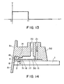
- Figure 13 is a schematic view of a configuration of a driving pulse.
- FIG 1 shows a state before the energy such as electric energy is applied to the heat generating element 2, and therefore, no heat has yet been generated.
- the movable member 31 is so positioned as to be faced at least to the downstream portion of the bubble generated by the heat generation of the heat generating element.
- the liquid flow passage structure is such that the movable member 31 extends at least to the position downstream (downstream of a line passing through the center 3 of the area of the heat generating element and perpendicular to the length of the flow path) of the center 3 of the area of the heat generating element.
- Figure 1 shows a state wherein the heat generation of heat generating element 2 occurs by the application of the electric energy to the heat generating element 2, and a part of of the liquid filled in the bubble generation region 11 is heated by the thus generated heat so that a bubble is generated through the film boiling.
- Figure 1 shows a state wherein the bubble 40 contracts and disappears by the decrease of the pressure in the bubble, peculiar to the film boiling phenomenon.
- a second liquid flow path 16 for the bubble generation is provided on the element substrate 1 which is provided with a heat generating element 2 for supplying thermal energy for generating the bubble in the liquid, and a first liquid flow path 14 for the ejection liquid in direct communication with the ejection outlet 18 is formed thereabove.
- a partition wall 30 is disposed, with a space for constituting a second liquid flow path, above an element substrate 1 provided with a heat generating resistor portion as the heat generating element 2 and wiring electrodes 5 for applying an electric signal to the heat generating resistor portion.
- the bubble generation pressure is not released in the three directions except for the upstream side in the bubble generation region, so that the pressure produced by the bubble generation is propagated concentratedly on the movable member 6 side in the ejection pressure generation portion, by which the movable member 6 is displaced from the position indicated in Figure 8, (a) toward the first liquid flow path side as indicated in Figure 8, (b) with the growth of the bubble.
- the first liquid flow path 14 and the second liquid flow path 16 are in wide fluid communication with each other, and the pressure produced by the generation of the bubble is mainly propagated toward the ejection outlet in the first liquid flow path (direction A).
- the liquid is ejected through the ejection outlet.
- a protection layer of silicon oxide, silicon nitride or the like of 0.1 - 2.0 ⁇ m thick is provided on the resistance layer, and in addition, an anti-cavitation layer of tantalum or the like (0.1 - 0.6 ⁇ m thick) is formed thereon to protect the resistance layer 105 from various liquid such as ink.
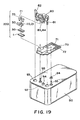
- a grooved member 50 has an orifice plate 51 having an ejection outlet 18, a plurality of grooves for constituting a plurality of first liquid flow paths 14 and a recess for constituting the first common liquid chamber 15 for supplying the liquid (ejection liquid) to the plurality of liquid flow paths 14.
- a separation wall 30 is mounted to the bottom of the grooved member 50 by which plurality of first liquid flow paths 14 are formed.
- Such a grooved member 50 has a first liquid supply passage 20 extending from an upper position to the first common liquid chamber 15.
- the grooved member 50 also has a second liquid supply passage 21 extending from an upper position to the second common liquid chamber 17 through the separation wall 30.
- the second liquid supply passage 21 is extended in parallel with the first liquid supply passage 20, but this is not limited to the exemplification, but it may be any if the liquid is supplied to the second common liquid chamber 17 through the separation wall 30 outside the first common liquid chamber 15.
- the one having the ingredient as used in conventional bubble jet device can be used as a recording liquid.
- the exposure operation was carried out in alignment with the alignment hole 100a of the element substrate 100, using an exposure device (MPA-600 available from CANON KABUSHIKI KAISHA, JAPAN) to remove the portions of the resist 103 which are going to be the second liquid flow path.
- the exposure amount was 800 mJ/cm 2 .
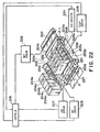
- Figure 21 is a block diagram for describing the general operation of an ink ejection recording apparatus which employs the liquid ejection method, and the liquid ejection head, in accordance with the present invention.
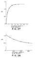
- the image density gradation can be effectively controlled as long as the dye concentration is no more than 3 wt. %. This is because when the dye concentration of the bubble generation liquid is reduced to a point no more than 3 wt. %, the rate of the density change remarkable improved. Further, in order to effectively control the image density gradation, it is important that a coloring material concentration range of no less than 0.3 wt. % is employed. This is because when the coloring material concentration is no more than 0.3 wt. %, it may be impossible sometimes to obtain sufficient optical density for the dark areas of the image.
Landscapes
- Engineering & Computer Science (AREA)
- Manufacturing & Machinery (AREA)
- Physics & Mathematics (AREA)
- Optics & Photonics (AREA)
- Particle Formation And Scattering Control In Inkjet Printers (AREA)
- Ink Jet (AREA)
- Application Of Or Painting With Fluid Materials (AREA)
- Printing Methods (AREA)
- Degasification And Air Bubble Elimination (AREA)
Claims (22)
- Flüssigkeitsausstoßverfahren mit den Schritten:gekennzeichnet durch:Bereitstellen eines Flüssigkeitsausstoßauslasses (18);Bereitstellen eines ersten Flüssigkeitsflußweges (10) für eine erste Flüssigkeit in Fluidverbindung mit dem Flüssigkeitsausstoßauslaß;Bereitstellen eines zweiten Flüssigkeitsflußweges (11) für eine zweite unterschiedliche Flüssigkeit; angrenzend zu dem ersten Flüssigkeitsflussweg; undBereitstellen einer Trennwand mit einem wiederherstellbaren bewegbaren Teil (31) zwischen dem ersten Flüssigkeitsflussweg (10) und dem zweiten Flüssigkeitsflussweg (11);Aktivieren eines Ausstoßenergie-Erzeugungsmittels (2) zum unter Druck setzen der zweiten Flüssigkeit in dem zweiten Flüssigkeitsflussweg (11), zum Umlegen des bewegbaren Teiles (31) in den ersten Flüssigkeitsflussweg (10), zum Veranlassen von der zweiten Flüssigkeit in den ersten Flüssigkeitsflussweg (10) einzudringen, um sich mit der ersten Flüssigkeit in dem ersten Flüssigkeitsflußweg (10) zu mischen, und zum Ausstoßen von einer Mischung von der ersten und zweiten Flüssigkeit als eine ausgestoßene gemischte Flüssigkeit durch den Ausstoßauslaß (18), so dass ein Mischungsverhältnis von der zweiten Flüssigkeit in der ausgestoßenen gemischten Flüssigkeit nicht geringer als 10 % Gewichtsanteil von der ersten Flüssigkeit, basierend auf der Menge von der ersten Flüssigkeit, hat.
- Verfahren nach Anspruch 1, wobei die gemischte Flüssigkeit ein Bild auf einem Aufnahmemedium aufnimmt, welches einen optischen Dichtewert von nicht weniger als 1,25 hat.
- Verfahren nach Anspruch 1 oder 2, wobei die erste Flüssigkeit Pigment enthält, und die zweite Flüssigkeit Farbstoff enthält.
- Verfahren nach Anspruch 1, wobei ein Aktivieren des Ausstoßenergie-Erzeugungsmittels eine Blase in dem zweiten Flüssigkeitsflussweg (11) erzeugt.
- Verfahren nach Anspruch 4, wobei das Blasenerzeugungsmittel ein thermisches Energieerzeugungsmittel enthält.
- Verfahren nach Anspruch 1, 2 oder 3, wobei das bewegbare Teil (31) ein freies Ende (32) angrenzend zum Flüssigkeitsausstoßauslaß (18) hat, wobei ein Widerstand in dem ersten Flüssigkeitsflussweg (10) gegen das bewegbare Teil in einer Umlegungsrichtung des bewegbaren Teiles (31) angrenzend zu einem Hebelstützenabschnitt (33) von dem bewegbaren Teil kleiner ist, als angrenzend zum freien Ende (32) von dem bewegbaren Teil, und wobei eine Blase in einer Blasenerzeugungsregion in dem zweiten Flüssigkeitsflussweg (11) erzeugt wird, und der durch die Blase hervorgebrachte Druck das freie Ende (32) von dem bewegbaren Teil (31) in den ersten Flüssigkeitsflussweg (10) umlegt, und der Druck in Richtung des Ausstoßauslasses (18) von dem ersten Flüssigkeitsflussweg (10) gerichtet wird, und somit die Flüssigkeit ausgestoßen wird.
- Verfahren nach Anspruch 1, 2 oder 3, wobei das bewegbare Teil (31) ein freies Ende (32) angrenzend zum Flüssigkeitsausstoßauslaß (18) hat, und der zweite Flüssigkeitsflussweg (11) eine Blasenerzeugungsregion hat, wobei das bewegbare Teil (31) gegenläufig zu der Blasenerzeugungsregion ist, und ein Widerstand in dem ersten Flüssigkeitsflussweg (10) gegen das bewegbare Teil (31) in einer Umlegungsrichtung des bewegbaren Teiles (31) angrenzend zu einem Hebelstützenabschnitt (33) des bewegbaren Teiles kleiner ist, als angrenzend zu dem freien Ende (32) des bewegbaren Teiles, wobei eine in der Blasenerzeugungsregion erzeugte Blase sich mehr in Richtung stromabwärts als in Richtung stromaufwärts, bezogen auf eine Richtung zu dem Ausstoßauslaß (18) erstreckt.
- Verfahren nach einem der vorhergehenden Ansprüche, wobei die Menge von der zweiten Flüssigkeit in der gemischten Flüssigkeit nicht mehr als 50 % Gewichtsanteil hat.
- Verfahren nach einem der Ansprüche 1 bis 7, wobei die Menge von der zweiten Flüssigkeit in der gemischten Flüssigkeit nicht mehr als 30 % Gewichtsanteil hat.
- Verfahren nach einem der Ansprüche 1 bis 7, wobei die Menge von der zweiten Flüssigkeit in der gemischten Flüssigkeit nicht mehr als 20 % Gewichtsanteil hat.
- Verfahren nach einem der Ansprüche 1 bis 7, wobei die Menge von der zweiten Flüssigkeit in der gemischten Flüssigkeit nicht mehr als 20 % Gewichtsanteil hat.
- Verfahren nach einem der Ansprüche 1 bis 7, wobei die erste Flüssigkeit 3 bis 4 % Gewichtsanteil an koloriertem Material enthält, und wobei die Menge von der zweiten Flüssigkeit in der gemischten Flüssigkeit nicht weniger als 20 % und nicht mehr als 50 % Gewichtsanteil hat.
- Verfahren nach einem der Ansprüche 1 bis 7, wobei die erste Flüssigkeit mehr als 5 % Gewichtsanteil an koloriertem Material enthält, und wobei die Menge von der zweiten Flüssigkeit in der gemischten Flüssigkeit nicht weniger als 20 % und nicht mehr als 150 % Gewichtsanteil hat.
- Verfahren nach Anspruch 1, wobei die erste Flüssigkeit 0,3 bis 3 % Gewichtsanteil an koloriertem Material enthält.
- Flüssigkeitsausstoßkopf mit:gekennzeichnet durch:einem Flüssigkeitsausstoßauslaß (18) ;einem ersten Flüssigkeitsflussweg (10) für eine erste Flüssigkeit in Fluidverbindung mit dem Flüssigkeitsausstoßauslaß (18) ;einem zweiten Flüssigkeitsflussweg (11) für eine zweite unterschiedliche Flüssigkeit angrenzend zu dem ersten Flüssigkeitsflussweg (10) ; undeiner Trennwand, welche ein wiederherstellbares bewegbares Teil (31) zwischen dem ersten Flüssigkeitsflussweg (10) und dem zweiten Flüssigkeitsflussweg (11) hat;einem Ausstoßenergie-Erzeugungsmittel (2) zum Erzeugen von Druck in der zweiten Flüssigkeit in dem zweiten Flüssigkeitsflussweg (11), um das bewegbare Teil (31) in den ersten Flüssigkeitsflussweg (10) umzulegen, um zu bewirken, dass die zweite Flüssigkeit in den ersten Flüssigkeitsflussweg (10) eindringt, um sich mit der ersten Flüssigkeit in dem ersten Flüssigkeitsflussweg (10) zu mischen und eine Mischung von der ersten und zweiten Flüssigkeit zu bewirken, welche ein Mischverhältnis von der zweiten Flüssigkeit von nicht weniger als 10 % vom Gewicht von der ersten Flüssigkeit hat, basierend auf der Menge von der als eine gemischte Flüssigkeit durch den Ausstoßauslaß (18) auszustoßenden ersten Flüssigkeit.
- Kopf nach Anspruch 15, wobei die erste Flüssigkeit 0,3 bis 3 % Gewichtsanteil an koloriertem Material enthält.
- Kopf nach Anspruch 15 oder 16, wobei der zweite Flüssigkeitsflussweg (11) mit einem Blasenerzeugungsmittel bereitgestellt ist, welches das Ausstoßenergie-Erzeugungsmittel ausbildet.
- Kopf nach Anspruch 14, 15 oder 16, wobei das Blasenerzeugungsmittel (2) ein thermisches Energieerzeugungsmittel enthält.
- Flüssigkeitsausstoßapparat mit:einem Flüssigkeitsausstoßkopf, wie in Anspruch 15, 16, 17 oder 18 beansprucht und einem Antriebssignal-Zuführmittel zum Zuführen eines Antriebssignals an den Flüssigkeitsausstoßkopf.
- Kopfkartusche mit:einem Flüssigkeitsausstoßkopf (510) wie in einem der Ansprüche 15 bis 18 beansprucht und einem Flüssigkeitscontainer (520) zum Beinhalten der an den Flüssigkeitsausstoßkopf zuzuführenden Flüssigkeit.
- Verfahren zum Herstellen eines Ausdruckproduktes, wobei das Verfahren ein Verwenden eines Verfahrens nach einem der Ansprüche 1 bis 14 zum Ausstoßen einer gemischten Flüssigkeit auf ein Aufnahmemedium enthält, wodurch das gedruckte Erzeugnis hergestellt wird.
- Einsatz mit:einem Flüssigkeitsausstoßkopf wie in einem der Ansprüche 15 bis 18 beansprucht;einem Flüssigkeitscontainer (520) zum Beinhalten von einer an den Flüssigkeitsausstoßkopf zuzuführenden Flüssigkeit; undeinem Füllabschnitt (530), welcher Flüssigkeit zum Füllen des Flüssigkeitscontainers (520) beinhaltet.
Priority Applications (1)
| Application Number | Priority Date | Filing Date | Title |
|---|---|---|---|
| EP02078670A EP1275506B1 (de) | 1995-04-26 | 1996-04-26 | Druckverfahren und druckvorrichtung zur tonabstufung |
Applications Claiming Priority (3)
| Application Number | Priority Date | Filing Date | Title |
|---|---|---|---|
| JP12731895 | 1995-04-26 | ||
| JP127318/95 | 1995-04-26 | ||
| JP12731895 | 1995-04-26 |
Related Child Applications (1)
| Application Number | Title | Priority Date | Filing Date |
|---|---|---|---|
| EP02078670A Division EP1275506B1 (de) | 1995-04-26 | 1996-04-26 | Druckverfahren und druckvorrichtung zur tonabstufung |
Publications (3)
| Publication Number | Publication Date |
|---|---|
| EP0739737A2 EP0739737A2 (de) | 1996-10-30 |
| EP0739737A3 EP0739737A3 (de) | 1997-07-09 |
| EP0739737B1 true EP0739737B1 (de) | 2003-03-05 |
Family
ID=14956975
Family Applications (2)
| Application Number | Title | Priority Date | Filing Date |
|---|---|---|---|
| EP02078670A Expired - Lifetime EP1275506B1 (de) | 1995-04-26 | 1996-04-26 | Druckverfahren und druckvorrichtung zur tonabstufung |
| EP96302936A Expired - Lifetime EP0739737B1 (de) | 1995-04-26 | 1996-04-26 | Flüssigkeitsausstosskopf, Flüssigkeitsausstossvorrichtung und Flüssigkeitsausstossverfahren |
Family Applications Before (1)
| Application Number | Title | Priority Date | Filing Date |
|---|---|---|---|
| EP02078670A Expired - Lifetime EP1275506B1 (de) | 1995-04-26 | 1996-04-26 | Druckverfahren und druckvorrichtung zur tonabstufung |
Country Status (11)
| Country | Link |
|---|---|
| US (1) | US6084616A (de) |
| EP (2) | EP1275506B1 (de) |
| KR (1) | KR100190413B1 (de) |
| CN (1) | CN1081542C (de) |
| AT (2) | ATE233661T1 (de) |
| AU (1) | AU720345B2 (de) |
| CA (1) | CA2175165C (de) |
| DE (2) | DE69634935T2 (de) |
| MX (1) | MX9601559A (de) |
| SG (1) | SG79193A1 (de) |
| TW (1) | TW334399B (de) |
Families Citing this family (26)
| Publication number | Priority date | Publication date | Assignee | Title |
|---|---|---|---|---|
| US5821962A (en) * | 1995-06-02 | 1998-10-13 | Canon Kabushiki Kaisha | Liquid ejection apparatus and method |
| AU726482B2 (en) * | 1995-06-02 | 2000-11-09 | Canon Kabushiki Kaisha | Liquid ejection apparatus and method |
| CN1121947C (zh) * | 1996-06-07 | 2003-09-24 | 佳能株式会社 | 喷液头和喷液设备以及制造喷液头的方法 |
| JP3652016B2 (ja) | 1996-07-12 | 2005-05-25 | キヤノン株式会社 | 液体吐出ヘッドおよび液体吐出方法 |
| JP3403010B2 (ja) * | 1996-07-12 | 2003-05-06 | キヤノン株式会社 | 液体吐出ヘッド |
| AUPP653998A0 (en) * | 1998-10-16 | 1998-11-05 | Silverbrook Research Pty Ltd | Micromechanical device and method (ij46B) |
| US7216956B2 (en) * | 1998-10-16 | 2007-05-15 | Silverbrook Research Pty Ltd | Printhead assembly with power and ground connections along single edge |
| ATE367927T1 (de) * | 1998-10-16 | 2007-08-15 | Silverbrook Res Pty Ltd | Verfahren zur herstellung einer düse für einen tintenstrahldruckkopf |
| DE69932392T2 (de) | 1998-12-03 | 2006-11-30 | Canon K.K. | Flüssigkeitsausstossverfahren, Flüssigkeitsausstosskopf, Verfahren zur Herstellung eines Flüssigkeitsausstosskopfes, Kopfkassette und Flüssigkeitsausstossgerät |
| AUPP823199A0 (en) * | 1999-01-15 | 1999-02-11 | Silverbrook Research Pty Ltd | Micromechanical device and method (IJ46L) |
| JP2001058409A (ja) * | 1999-08-23 | 2001-03-06 | Canon Inc | インクジェット記録ヘッド、インクジェット記録ヘッドカーリッジ、およびインクジェット記録装置 |
| US6834423B2 (en) * | 2000-07-31 | 2004-12-28 | Canon Kabushiki Kaisha | Method of manufacturing a liquid discharge head |
| DE60110875T2 (de) * | 2000-10-04 | 2006-05-04 | Canon K.K. | Kopfreinigungsvorrichtung, Kopfreinigungsverfahren und Tintenstrahlaufzeichnungsgerät |
| JP2002166553A (ja) * | 2000-11-30 | 2002-06-11 | Canon Inc | 液体吐出ヘッドおよび液体吐出ヘッドの製造方法 |
| US6527378B2 (en) * | 2001-04-20 | 2003-03-04 | Hewlett-Packard Company | Thermal ink jet defect tolerant resistor design |
| US6682186B2 (en) * | 2001-06-08 | 2004-01-27 | Hewlett-Packard Development Company, Lp. | Graded capillarity structures for passive gas management, and methods |
| GB2379414A (en) * | 2001-09-10 | 2003-03-12 | Seiko Epson Corp | Method of forming a large flexible electronic display on a substrate using an inkjet head(s) disposed about a vacuum roller holding the substrate |
| US6428140B1 (en) * | 2001-09-28 | 2002-08-06 | Hewlett-Packard Company | Restriction within fluid cavity of fluid drop ejector |
| US7954930B2 (en) * | 2006-11-30 | 2011-06-07 | Fuji Xerox Co., Ltd. | Liquid droplet ejecting head and liquid droplet ejecting apparatus |
| CN105284362A (zh) * | 2015-11-01 | 2016-02-03 | 十堰智脑中药材专业合作社 | 一种金银花套种辣椒、复种秋油菜的栽培方法 |
| IE20190171A3 (en) | 2018-10-15 | 2020-10-14 | Juul Labs Inc | Heating element |
| US12256784B2 (en) | 2018-10-17 | 2025-03-25 | Juul Labs, Inc. | Cartridge for a vaporizer device |
| WO2021076657A2 (en) * | 2019-10-14 | 2021-04-22 | Juul Labs, Inc. | Vaporizer device microfluidic systems and apparatuses |
| EP4099856B1 (de) | 2020-02-04 | 2025-02-26 | Juul Labs, Inc. | Aerosolabgabevorrichtung mit einwegbehälter |
| EP4473854B1 (de) | 2020-04-15 | 2026-01-14 | Juul Labs, Inc. | Kartusche für eine verdampfervorrichtung |
| CN114889333B (zh) * | 2022-04-27 | 2023-02-10 | 华中科技大学 | 一种消除喷印过程中气泡缺陷的调控方法和装置 |
Family Cites Families (18)
| Publication number | Priority date | Publication date | Assignee | Title |
|---|---|---|---|---|
| GB1558765A (en) * | 1976-02-05 | 1980-01-09 | Nat Res Dev | Printing apparatus |
| CA1127227A (en) | 1977-10-03 | 1982-07-06 | Ichiro Endo | Liquid jet recording process and apparatus therefor |
| JPS5581172A (en) * | 1978-12-14 | 1980-06-18 | Canon Inc | Liquid injection type recording method and device |
| US4480259A (en) * | 1982-07-30 | 1984-10-30 | Hewlett-Packard Company | Ink jet printer with bubble driven flexible membrane |
| US4494128A (en) * | 1982-09-17 | 1985-01-15 | Hewlett-Packard Company | Gray scale printing with ink jets |
| JPS6169467A (ja) * | 1985-06-11 | 1986-04-10 | Seiko Epson Corp | 記録液滴吐出型記録装置 |
| JPS63199972A (ja) * | 1987-02-13 | 1988-08-18 | Canon Inc | 弁素子の製造方法 |
| EP0436047A1 (de) * | 1990-01-02 | 1991-07-10 | Siemens Aktiengesellschaft | Flüssigkeitsstrahlaufzeichnungskopf für Tintendruckeinrichtungen |
| JP3161635B2 (ja) * | 1991-10-17 | 2001-04-25 | ソニー株式会社 | インクジェットプリントヘッド及びインクジェットプリンタ |
| JPH05124189A (ja) * | 1991-11-01 | 1993-05-21 | Matsushita Electric Ind Co Ltd | インク吐出装置 |
| JP3095842B2 (ja) * | 1991-12-26 | 2000-10-10 | 株式会社リコー | インクジェット記録装置 |
| US5278585A (en) * | 1992-05-28 | 1994-01-11 | Xerox Corporation | Ink jet printhead with ink flow directing valves |
| JPH0671881A (ja) * | 1992-08-07 | 1994-03-15 | Sony Corp | インクジェットプリントヘッド及びインクジェットプリンタ |
| JP3158374B2 (ja) * | 1992-08-12 | 2001-04-23 | ソニー株式会社 | インクジェットプリントヘッド及びインクジェットプリンタ |
| JPH06246935A (ja) * | 1993-03-01 | 1994-09-06 | Seiko Epson Corp | インクジェット記録装置 |
| US6036295A (en) * | 1993-11-26 | 2000-03-14 | Sony Corporation | Ink jet printer head and method for manufacturing the same |
| US5581287A (en) * | 1994-06-30 | 1996-12-03 | Jetfill, Inc. | Inkjet printer ink cartridge refilling structure |
| US5821962A (en) * | 1995-06-02 | 1998-10-13 | Canon Kabushiki Kaisha | Liquid ejection apparatus and method |
-
1996
- 1996-04-23 TW TW085104863A patent/TW334399B/zh not_active IP Right Cessation
- 1996-04-26 DE DE69634935T patent/DE69634935T2/de not_active Expired - Fee Related
- 1996-04-26 SG SG9609583A patent/SG79193A1/en unknown
- 1996-04-26 KR KR1019960013123A patent/KR100190413B1/ko not_active Expired - Fee Related
- 1996-04-26 AT AT96302936T patent/ATE233661T1/de not_active IP Right Cessation
- 1996-04-26 US US08/638,101 patent/US6084616A/en not_active Expired - Fee Related
- 1996-04-26 MX MX9601559A patent/MX9601559A/es unknown
- 1996-04-26 AU AU50896/96A patent/AU720345B2/en not_active Ceased
- 1996-04-26 EP EP02078670A patent/EP1275506B1/de not_active Expired - Lifetime
- 1996-04-26 AT AT02078670T patent/ATE299438T1/de not_active IP Right Cessation
- 1996-04-26 CA CA002175165A patent/CA2175165C/en not_active Expired - Fee Related
- 1996-04-26 DE DE69626436T patent/DE69626436T2/de not_active Expired - Fee Related
- 1996-04-26 CN CN96105651A patent/CN1081542C/zh not_active Expired - Fee Related
- 1996-04-26 EP EP96302936A patent/EP0739737B1/de not_active Expired - Lifetime
Also Published As
| Publication number | Publication date |
|---|---|
| DE69634935T2 (de) | 2006-05-18 |
| AU5089696A (en) | 1996-11-07 |
| DE69634935D1 (de) | 2005-08-18 |
| EP1275506B1 (de) | 2005-07-13 |
| DE69626436T2 (de) | 2003-10-23 |
| KR960037286A (ko) | 1996-11-19 |
| TW334399B (en) | 1998-06-21 |
| SG79193A1 (en) | 2001-03-20 |
| ATE233661T1 (de) | 2003-03-15 |
| KR100190413B1 (ko) | 1999-06-01 |
| DE69626436D1 (de) | 2003-04-10 |
| ATE299438T1 (de) | 2005-07-15 |
| EP0739737A2 (de) | 1996-10-30 |
| CA2175165A1 (en) | 1996-10-27 |
| AU720345B2 (en) | 2000-05-25 |
| EP0739737A3 (de) | 1997-07-09 |
| US6084616A (en) | 2000-07-04 |
| CA2175165C (en) | 2000-10-17 |
| MX9601559A (es) | 1997-06-28 |
| CN1081542C (zh) | 2002-03-27 |
| CN1150930A (zh) | 1997-06-04 |
| EP1275506A1 (de) | 2003-01-15 |
Similar Documents
| Publication | Publication Date | Title |
|---|---|---|
| EP1275506B1 (de) | Druckverfahren und druckvorrichtung zur tonabstufung | |
| US6334669B1 (en) | Liquid ejecting head, liquid ejecting device and liquid ejecting method | |
| US6305789B1 (en) | Liquid ejecting head, liquid ejecting device and liquid ejecting method | |
| EP0764531B1 (de) | Flüssigkeitsausstosskopf, Vorrichtung zum Ausstossen von Flüssigkeit und Verfahren zur Wiederherstellung derselben | |
| US6113224A (en) | Liquid ejecting method, liquid ejecting head, head cartridge and liquid ejecting apparatus using same | |
| AU707573B2 (en) | Liquid ejecting method, liquid ejecting head and liquid ejecting apparatus in which motion of a moveable member is controlled | |
| EP0761439B1 (de) | Verfahren zum Ausstossen von Flüssigkeit, Flüssigkeitsausstosskopf und Kassette dazu | |
| AU756345B2 (en) | Liquid ejecting head, liquid ejecting device and liquid ejecting method | |
| AU727463B2 (en) | Liquid ejecting head, liquid ejecting device and liquid ejecting method | |
| AU761385B2 (en) | Liquid ejecting head, liquid ejecting device and liquid ejecting method | |
| AU754506B2 (en) | Liquid ejecting head, liquid ejecting device and liquid ejecting method | |
| AU779656B2 (en) | Liquid ejecting method, liquid ejecting head, and head cartridge using same | |
| AU727517B2 (en) | Liquid ejecting head, liquid ejecting device and liquid ejecting method | |
| AU2003271289B2 (en) | Liquid Ejection Head, Apparatus and Recovery Method for Them | |
| HK1014693B (en) | Liquid ejecting head, liquid ejecting device and liquid ejecting method | |
| JPH09327919A (ja) | 液体吐出ヘッド、液体吐出装置、および記録方法 | |
| AU4751599A (en) | Liquid ejecting method, liquid ejecting head, and head cartridge using same |
Legal Events
| Date | Code | Title | Description |
|---|---|---|---|
| PUAI | Public reference made under article 153(3) epc to a published international application that has entered the european phase |
Free format text: ORIGINAL CODE: 0009012 |
|
| AK | Designated contracting states |
Kind code of ref document: A2 Designated state(s): AT BE CH DE DK ES FI FR GB GR IE IT LI LU NL PT SE |
|
| PUAL | Search report despatched |
Free format text: ORIGINAL CODE: 0009013 |
|
| AK | Designated contracting states |
Kind code of ref document: A3 Designated state(s): AT BE CH DE DK ES FI FR GB GR IE IT LI LU NL PT SE |
|
| 17P | Request for examination filed |
Effective date: 19971119 |
|
| 17Q | First examination report despatched |
Effective date: 19990615 |
|
| GRAG | Despatch of communication of intention to grant |
Free format text: ORIGINAL CODE: EPIDOS AGRA |
|
| GRAG | Despatch of communication of intention to grant |
Free format text: ORIGINAL CODE: EPIDOS AGRA |
|
| GRAG | Despatch of communication of intention to grant |
Free format text: ORIGINAL CODE: EPIDOS AGRA |
|
| GRAH | Despatch of communication of intention to grant a patent |
Free format text: ORIGINAL CODE: EPIDOS IGRA |
|
| GRAH | Despatch of communication of intention to grant a patent |
Free format text: ORIGINAL CODE: EPIDOS IGRA |
|
| GRAA | (expected) grant |
Free format text: ORIGINAL CODE: 0009210 |
|
| AK | Designated contracting states |
Designated state(s): AT BE CH DE DK ES FI FR GB GR IE IT LI LU NL PT SE |
|
| PG25 | Lapsed in a contracting state [announced via postgrant information from national office to epo] |
Ref country code: NL Free format text: LAPSE BECAUSE OF FAILURE TO SUBMIT A TRANSLATION OF THE DESCRIPTION OR TO PAY THE FEE WITHIN THE PRESCRIBED TIME-LIMIT Effective date: 20030305 Ref country code: LI Free format text: LAPSE BECAUSE OF FAILURE TO SUBMIT A TRANSLATION OF THE DESCRIPTION OR TO PAY THE FEE WITHIN THE PRESCRIBED TIME-LIMIT Effective date: 20030305 Ref country code: GR Free format text: LAPSE BECAUSE OF FAILURE TO SUBMIT A TRANSLATION OF THE DESCRIPTION OR TO PAY THE FEE WITHIN THE PRESCRIBED TIME-LIMIT Effective date: 20030305 Ref country code: FI Free format text: LAPSE BECAUSE OF FAILURE TO SUBMIT A TRANSLATION OF THE DESCRIPTION OR TO PAY THE FEE WITHIN THE PRESCRIBED TIME-LIMIT Effective date: 20030305 Ref country code: CH Free format text: LAPSE BECAUSE OF FAILURE TO SUBMIT A TRANSLATION OF THE DESCRIPTION OR TO PAY THE FEE WITHIN THE PRESCRIBED TIME-LIMIT Effective date: 20030305 Ref country code: BE Free format text: LAPSE BECAUSE OF FAILURE TO SUBMIT A TRANSLATION OF THE DESCRIPTION OR TO PAY THE FEE WITHIN THE PRESCRIBED TIME-LIMIT Effective date: 20030305 Ref country code: AT Free format text: LAPSE BECAUSE OF FAILURE TO SUBMIT A TRANSLATION OF THE DESCRIPTION OR TO PAY THE FEE WITHIN THE PRESCRIBED TIME-LIMIT Effective date: 20030305 |
|
| REG | Reference to a national code |
Ref country code: GB Ref legal event code: FG4D |
|
| REG | Reference to a national code |
Ref country code: CH Ref legal event code: EP |
|
| REG | Reference to a national code |
Ref country code: IE Ref legal event code: FG4D |
|
| REF | Corresponds to: |
Ref document number: 69626436 Country of ref document: DE Date of ref document: 20030410 Kind code of ref document: P |
|
| PG25 | Lapsed in a contracting state [announced via postgrant information from national office to epo] |
Ref country code: LU Free format text: LAPSE BECAUSE OF NON-PAYMENT OF DUE FEES Effective date: 20030426 |
|
| PG25 | Lapsed in a contracting state [announced via postgrant information from national office to epo] |
Ref country code: IE Free format text: LAPSE BECAUSE OF NON-PAYMENT OF DUE FEES Effective date: 20030428 |
|
| PG25 | Lapsed in a contracting state [announced via postgrant information from national office to epo] |
Ref country code: SE Free format text: LAPSE BECAUSE OF FAILURE TO SUBMIT A TRANSLATION OF THE DESCRIPTION OR TO PAY THE FEE WITHIN THE PRESCRIBED TIME-LIMIT Effective date: 20030605 Ref country code: PT Free format text: LAPSE BECAUSE OF FAILURE TO SUBMIT A TRANSLATION OF THE DESCRIPTION OR TO PAY THE FEE WITHIN THE PRESCRIBED TIME-LIMIT Effective date: 20030605 Ref country code: DK Free format text: LAPSE BECAUSE OF FAILURE TO SUBMIT A TRANSLATION OF THE DESCRIPTION OR TO PAY THE FEE WITHIN THE PRESCRIBED TIME-LIMIT Effective date: 20030605 |
|
| NLV1 | Nl: lapsed or annulled due to failure to fulfill the requirements of art. 29p and 29m of the patents act | ||
| REG | Reference to a national code |
Ref country code: CH Ref legal event code: PL |
|
| ET | Fr: translation filed | ||
| PG25 | Lapsed in a contracting state [announced via postgrant information from national office to epo] |
Ref country code: ES Free format text: LAPSE BECAUSE OF FAILURE TO SUBMIT A TRANSLATION OF THE DESCRIPTION OR TO PAY THE FEE WITHIN THE PRESCRIBED TIME-LIMIT Effective date: 20030930 |
|
| PLBE | No opposition filed within time limit |
Free format text: ORIGINAL CODE: 0009261 |
|
| STAA | Information on the status of an ep patent application or granted ep patent |
Free format text: STATUS: NO OPPOSITION FILED WITHIN TIME LIMIT |
|
| REG | Reference to a national code |
Ref country code: IE Ref legal event code: MM4A |
|
| 26N | No opposition filed |
Effective date: 20031208 |
|
| PGFP | Annual fee paid to national office [announced via postgrant information from national office to epo] |
Ref country code: DE Payment date: 20070627 Year of fee payment: 12 |
|
| PGFP | Annual fee paid to national office [announced via postgrant information from national office to epo] |
Ref country code: GB Payment date: 20070416 Year of fee payment: 12 |
|
| PGFP | Annual fee paid to national office [announced via postgrant information from national office to epo] |
Ref country code: IT Payment date: 20070612 Year of fee payment: 12 |
|
| PGFP | Annual fee paid to national office [announced via postgrant information from national office to epo] |
Ref country code: FR Payment date: 20070419 Year of fee payment: 12 |
|
| GBPC | Gb: european patent ceased through non-payment of renewal fee |
Effective date: 20080426 |
|
| PG25 | Lapsed in a contracting state [announced via postgrant information from national office to epo] |
Ref country code: DE Free format text: LAPSE BECAUSE OF NON-PAYMENT OF DUE FEES Effective date: 20081101 |
|
| REG | Reference to a national code |
Ref country code: FR Ref legal event code: ST Effective date: 20081231 |
|
| PG25 | Lapsed in a contracting state [announced via postgrant information from national office to epo] |
Ref country code: FR Free format text: LAPSE BECAUSE OF NON-PAYMENT OF DUE FEES Effective date: 20080430 |
|
| PG25 | Lapsed in a contracting state [announced via postgrant information from national office to epo] |
Ref country code: GB Free format text: LAPSE BECAUSE OF NON-PAYMENT OF DUE FEES Effective date: 20080426 |
|
| PG25 | Lapsed in a contracting state [announced via postgrant information from national office to epo] |
Ref country code: IT Free format text: LAPSE BECAUSE OF NON-PAYMENT OF DUE FEES Effective date: 20080426 |