EP0722003A2 - Bloc de filage pour une installation de filage au fondu contenant un dispositif de chauffage pour chauffer un bloc de filage à plusieurs parties - Google Patents
Bloc de filage pour une installation de filage au fondu contenant un dispositif de chauffage pour chauffer un bloc de filage à plusieurs parties Download PDFInfo
- Publication number
- EP0722003A2 EP0722003A2 EP96100005A EP96100005A EP0722003A2 EP 0722003 A2 EP0722003 A2 EP 0722003A2 EP 96100005 A EP96100005 A EP 96100005A EP 96100005 A EP96100005 A EP 96100005A EP 0722003 A2 EP0722003 A2 EP 0722003A2
- Authority
- EP
- European Patent Office
- Prior art keywords
- spinning block
- spinning
- heating
- heating elements
- block according
- Prior art date
- Legal status (The legal status is an assumption and is not a legal conclusion. Google has not performed a legal analysis and makes no representation as to the accuracy of the status listed.)
- Withdrawn
Links
- 238000009987 spinning Methods 0.000 title claims abstract description 99
- 238000010438 heat treatment Methods 0.000 title claims abstract description 98
- 238000002074 melt spinning Methods 0.000 title claims abstract description 7
- 238000009434 installation Methods 0.000 title description 2
- 238000012423 maintenance Methods 0.000 claims abstract description 6
- 239000000463 material Substances 0.000 claims description 15
- 239000000155 melt Substances 0.000 claims description 10
- 229910052751 metal Inorganic materials 0.000 claims description 9
- 239000002184 metal Substances 0.000 claims description 9
- 238000009827 uniform distribution Methods 0.000 claims description 2
- 229920001169 thermoplastic Polymers 0.000 claims 1
- 239000012768 molten material Substances 0.000 abstract 1
- 238000004519 manufacturing process Methods 0.000 description 4
- 239000000835 fiber Substances 0.000 description 3
- 229910045601 alloy Inorganic materials 0.000 description 2
- 239000000956 alloy Substances 0.000 description 2
- 238000001816 cooling Methods 0.000 description 2
- 230000002349 favourable effect Effects 0.000 description 2
- 150000002739 metals Chemical class 0.000 description 2
- 229910018125 Al-Si Inorganic materials 0.000 description 1
- 229910018520 Al—Si Inorganic materials 0.000 description 1
- 229910018566 Al—Si—Mg Inorganic materials 0.000 description 1
- 229910000831 Steel Inorganic materials 0.000 description 1
- 238000004140 cleaning Methods 0.000 description 1
- 238000010276 construction Methods 0.000 description 1
- 238000007380 fibre production Methods 0.000 description 1
- 230000003993 interaction Effects 0.000 description 1
- 239000007788 liquid Substances 0.000 description 1
- 238000002844 melting Methods 0.000 description 1
- 238000000034 method Methods 0.000 description 1
- 230000000149 penetrating effect Effects 0.000 description 1
- 229920000728 polyester Polymers 0.000 description 1
- -1 polyethylene terephthalate Polymers 0.000 description 1
- 229920000139 polyethylene terephthalate Polymers 0.000 description 1
- 239000005020 polyethylene terephthalate Substances 0.000 description 1
- 229920000642 polymer Polymers 0.000 description 1
- 230000001105 regulatory effect Effects 0.000 description 1
- 238000000926 separation method Methods 0.000 description 1
- 239000011343 solid material Substances 0.000 description 1
- 239000010959 steel Substances 0.000 description 1
- 239000012209 synthetic fiber Substances 0.000 description 1
- 229920002994 synthetic fiber Polymers 0.000 description 1
Images


Classifications
-
- D—TEXTILES; PAPER
- D01—NATURAL OR MAN-MADE THREADS OR FIBRES; SPINNING
- D01D—MECHANICAL METHODS OR APPARATUS IN THE MANUFACTURE OF ARTIFICIAL FILAMENTS, THREADS, FIBRES, BRISTLES OR RIBBONS
- D01D4/00—Spinnerette packs; Cleaning thereof
- D01D4/08—Supporting spinnerettes or other parts of spinnerette packs
-
- D—TEXTILES; PAPER
- D01—NATURAL OR MAN-MADE THREADS OR FIBRES; SPINNING
- D01D—MECHANICAL METHODS OR APPARATUS IN THE MANUFACTURE OF ARTIFICIAL FILAMENTS, THREADS, FIBRES, BRISTLES OR RIBBONS
- D01D4/00—Spinnerette packs; Cleaning thereof
Definitions
- Spinning block for melt spinning systems containing a heating device for heating a multi-part spinning block
- the present invention relates to a spinning block for melt spinning plants from one or more interconnected metal blocks containing a filter for the melt, a nozzle plate and a heating device.
- spinning blocks or spinning heads for heating them are arranged in heating boxes through which a suitable heating medium (liquid, steam) flows.
- a suitable heating medium liquid, steam
- Such externally heated spinning blocks are described, for example, in EP 0 271 801.
- Such arrangements are structurally very complex since supply lines, such as pipes, and external heating devices are required for the heating medium.
- EP 0 008 612 discloses elongated, recessed heating elements for the additional heating of nozzle plates. These heating elements are located exclusively in the area of the nozzle plate and are not suitable for replacing the heating devices described at the beginning for a multi-part spinning head.
- the present invention has for its object to provide a simplified design of a heating device for heating multi-part spinning blocks that contain a filter, so that there is a uniform heating of the individual parts and the filter with easy disassembly for the purpose of maintenance (e.g.. Replacing the filter or the nozzle plate, cleaning). Not insignificant interruptions in production can result if the spinning block cannot be heated up to the intended working temperature quickly enough after removal and subsequent reinstallation.
- the heating system should therefore have the lowest possible thermal inertia. It is particularly expedient if the spinning block can be heated independently in the removed state, so that the spinning block can be brought to the required operating temperature before installation.
- the spinning block consists of one or more interconnected metal blocks (6, 7) containing a filter (9) for the melt, a nozzle plate (10) and a heating device, and is characterized in that the heating device heats the spinning block from the inside, from one or several heating elements (11) of elongated shape and the elements are arranged in a uniform distribution around the axis of the main flow direction of the melt so that they penetrate the entire spinning block and are removed for changing the filter or the nozzle plate or for the purpose of maintenance can.
- the spinning block according to the invention can be heated independently and therefore in principle does not require any additional external heating, it may be desirable to install the spinning block (s) according to the invention in a spinning beam known per se for the purpose of heating and / or holding in a manner known per se. If these known spinning beams have their own heating devices, it can be advantageous if these heating devices interact with the heating devices of the spinning block according to the invention. This interaction can take place during the actual spinning of the fibers or also during the assembly or disassembly of the spinning block in or out of the spinning beam and / or during the change of the filter.
- the spinning block is basically suitable for the production of all types of synthetic fibers known per se, spun from the melt.
- the shape of the spinning blocks can be largely arbitrary, but should expediently be as simple as possible. Such suitable simple designs are essentially cylindrically symmetrical about the main flow direction of the melt, in particular according to FIG. 1 essentially cuboid. If the spinning blocks according to the invention are installed in already existing or also newly constructed spinning beams, a shape is recommended which allows a technically simple fastening.
- the heat transfer plays here Although not as important because of the heating device present in the spinning block as when using non-heated spinning blocks known per se, it can expediently be optimized in accordance with the usual technical measures.
- the required spinning beams can either be heated by themselves or simply perform the function of a carrier for the spinning block or blocks.
- the material from which the spinning block is made should have the greatest possible thermal conductivity. All materials customary for the production of spinning blocks are expedient. Sufficient noble or refined metals are preferably used, in particular VA steels are used. The linear thermal expansion coefficient of these materials is preferably less than 17 * 10 -6 (° C) -1 , in particular less than 12 * 10 -6 (° C) -1 .
- the spinning block is to be constructed in such a way that the heat exchange between areas of different temperatures is as large as possible.
- the spinning blocks should therefore preferably be made from solid material in order to avoid cavities with low thermal conductivity. If the spinning block is composed of several parts, the contact surfaces between the parts must be dimensioned as large as possible and designed without gaps.
- the heating elements penetrating the spinning block are manufactured in such a way that they can be easily inserted into and removed from the spinning block in the cooled state.
- the shape of the cavity and the shape of the heating elements are preferably cylindrical. It is only important that the shape of the heating element matches the shape of the cavity as much as possible in the context of the thermal expansion of the materials.
- the end of the heating rod which abuts the end of the cavity when fully inserted, is shaped in such a way that there is almost no cavity between the heating rod and the spinning block.
- Heating elements are particularly preferred which, for better heat transfer between the heating element and spinning block, e.g. mechanically pressed into the cavity. This pressure only has to be applied until the heating elements have expanded so far after heating that they hold themselves in the specified position.
- the heating elements can be heated using methods known per se, is preferred but an electric heater, especially an electric resistance heater.
- the material which essentially contains the heating elements preferably has a thermal expansion which is greater than the thermal expansion of the material from which the parts of the spinning block are made.
- the heating element can also be constructed in such a way that the heating element is encased by the higher thermal expansion material.
- relatively low-melting metals, preferably alloys are used as the material for the heating elements. Alloys such as Al-Si cast or Al-Si-Mg cast with linear expansion coefficients around 20.5 * 10 -6 (° C) -1 are particularly preferred.
- the parts of the spinning block be made entirely of material with less thermal expansion. It is only important that the volume of the cavity, in which the heating elements are located, increases less when heated than the volume of the heating element therein, so that the heat transfer between the heating element and the spinning block is improved.
- the ratio of the thermal expansion between the material surrounding the heating element and the higher thermal expansion material of the heating element is greater than 1: 1.05, preferably greater than 1: 1.5, in particular greater than 1: 1.7.
- the gap or cavity between the heating element and the spinning block must be as small as possible, but care must be taken to ensure that, in the case of large thermal expansion ratios, the pressure due to the different expansion of the materials is not greater than the mechanical strength of the stressed parts. Such tensions can be reduced by increasing the gap between the heating element and the spinning block. This can then reduce the pressure between the different thermal expansion materials to the desired level.
- the gap is preferably made as narrow as possible.
- Spinning blocks which consist of a plurality of interconnected metal blocks and in which the longitudinal axis of the heating elements is oriented such that the individual metal blocks can be separated from one another without prior removal of the heating elements, are expedient. This separation is preferably carried out in the cooled state.
- heating devices which are continuous and thereby heat all parts of the spinning block at the same time are advantageous.
- the arrangement of the heating element or the heating elements is particularly favorable if there is a simplification in the disassembly for changing the filter or the nozzle plate. Constructions in which the heating elements can be inserted and removed from above are particularly preferred.
- the spinning block according to the invention can be heated independently in the removed state. When removed, heating can be carried out using a second set of heating elements. However, it is also possible to design the electrical leads to the heating elements to be pluggable in order to connect the elements to an external supply and control.
- the heating elements can work continuously for uniform heating with almost the same heating output, but can also be divided into several independently heatable zones in order to heat to different extents in the individual heating element zones, so that temperature differences in the spinning block can be compensated for or certain desired temperature differences can be caused thereby.
- the temperature of the spinning block can be regulated with the aid of the signal from one or more thermal sensors.
- the thermal sensors can be arranged inside the heating element or also outside, for example in the spinning block, near the filter, in the area of the melt inlet or on or in the nozzle plate. The arrangement inside the heating element is preferred.
- FIG. 1 shows a spinning block with feed lines in a perspective view.
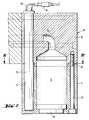
- Fig. 2 shows the spinning block in longitudinal section (ll-ll).
- Fig. 3 shows a cross section through the spinning block (III-III).
- the melt flows through a feed line (1) via a pump connected to the flange (2) and is then fed to the actual spinning block (3).
- the Spin block there are holes (4) for receiving the heating elements.
- the spinning block is composed of an upper (6) and a lower block (7) and can be separated on the surface (5).
- the polymer melt enters the filter (9) via the feed line (8), first penetrates the filter and then the nozzle plate (10) which closes the spinning block at the bottom.
- the electrically heated heating elements (11) are inserted into the bores (4) and are connected to a power supply, possibly with a control device, via a cable (13) and a plug (14).
- the two parts of the spinning block are connected to each other by screws (15).
- the heating elements (11) and the screws (15) are arranged in a ring around the filter (9).
- the spinning block constructed according to the invention offers considerable advantages during fiber production.
- maintenance is simplified since the heating elements can be removed from the spinning block in a simple manner.
- the removal after the cooling of the spinning block is particularly advantageous since, due to the different thermal expansion, a space is created between the heating element and the spinning block.
- the elements can be removed much more easily if the elements penetrate all parts of the block to be heated.
- the spinning block according to the invention is characterized by surprisingly simple dismantling for changing the filter or the nozzle plate or for the purpose of maintenance. It is possible to remove the heating elements before disassembly. It is particularly expedient to carry out the disassembly of the spinning block with the heating elements used, since this requires a particularly small number of work steps.
- the heating elements designed and arranged according to the invention enable the spinning block to be heated in an extremely advantageous manner.
- the heating of the spinning block from the inside enables a particularly direct heat emission.
- Multi-part spinning blocks can be heated much more easily with elements that penetrate all parts of the block to be heated.
- the heating elements have an elongated shape and are arranged in the direction of the axis of the main flow direction of the melt. If the heating elements are arranged uniformly, preferably in a ring around this axis, particularly favorable heating can be achieved.
- the heating elements according to the invention enable improved heat transfer between the heating element and the spinning block.
- the intimate contact enables a high heat flow, which allows the temperature of the spinning block to be set extremely quickly.
Landscapes
- Engineering & Computer Science (AREA)
- Mechanical Engineering (AREA)
- Textile Engineering (AREA)
- Spinning Methods And Devices For Manufacturing Artificial Fibers (AREA)
Applications Claiming Priority (2)
| Application Number | Priority Date | Filing Date | Title |
|---|---|---|---|
| DE19500502 | 1995-01-10 | ||
| DE1995100502 DE19500502A1 (de) | 1995-01-10 | 1995-01-10 | Spinnblock für Schmelzspinnanlagen enthaltend eine Heizeinrichtung zur Beheizung eines mehrteilig zusammengesetzten Spinnblocks |
Publications (2)
| Publication Number | Publication Date |
|---|---|
| EP0722003A2 true EP0722003A2 (fr) | 1996-07-17 |
| EP0722003A3 EP0722003A3 (fr) | 1997-08-06 |
Family
ID=7751207
Family Applications (1)
| Application Number | Title | Priority Date | Filing Date |
|---|---|---|---|
| EP96100005A Withdrawn EP0722003A3 (fr) | 1995-01-10 | 1996-01-02 | Bloc de filage pour une installation de filage au fondu contenant un dispositif de chauffage pour chauffer un bloc de filage à plusieurs parties |
Country Status (4)
| Country | Link |
|---|---|
| EP (1) | EP0722003A3 (fr) |
| JP (1) | JPH08232113A (fr) |
| BR (1) | BR9600081A (fr) |
| DE (1) | DE19500502A1 (fr) |
Cited By (2)
| Publication number | Priority date | Publication date | Assignee | Title |
|---|---|---|---|---|
| DE19829272A1 (de) * | 1998-07-01 | 2000-01-05 | Rieter Automatik Gmbh | Heizsystem für schmelzeführende Teile |
| US12037713B2 (en) | 2020-01-10 | 2024-07-16 | Kimberly-Clark Worldwide, Inc. | Method of making uniform spunbond filament nonwoven webs |
Families Citing this family (1)
| Publication number | Priority date | Publication date | Assignee | Title |
|---|---|---|---|---|
| CN108103591B (zh) * | 2018-02-07 | 2023-06-20 | 苏州金泉新材料股份有限公司 | 纺丝熔体过滤装置 |
Citations (2)
| Publication number | Priority date | Publication date | Assignee | Title |
|---|---|---|---|---|
| EP0008612A1 (fr) | 1978-08-30 | 1980-03-19 | Hüls Troisdorf Aktiengesellschaft | Procédé et appareil pour fabriquer des monofilaments de poly(fluorure de vinylidène) |
| EP0271801A2 (fr) | 1986-12-16 | 1988-06-22 | B a r m a g AG | Ensemble de filage |
Family Cites Families (2)
| Publication number | Priority date | Publication date | Assignee | Title |
|---|---|---|---|---|
| DE3113495C2 (de) * | 1981-04-03 | 1989-11-02 | Davy McKee AG, 6000 Frankfurt | Spinnbalken für Schmelzspinnanlagen für synthetische Hochpolymere |
| EP0122464B1 (fr) * | 1983-03-23 | 1988-11-09 | B a r m a g AG | Tête de filage pour le filage au fondu de filaments |
-
1995
- 1995-01-10 DE DE1995100502 patent/DE19500502A1/de not_active Withdrawn
-
1996
- 1996-01-02 EP EP96100005A patent/EP0722003A3/fr not_active Withdrawn
- 1996-01-08 JP JP74696A patent/JPH08232113A/ja active Pending
- 1996-01-09 BR BR9600081A patent/BR9600081A/pt not_active Application Discontinuation
Patent Citations (2)
| Publication number | Priority date | Publication date | Assignee | Title |
|---|---|---|---|---|
| EP0008612A1 (fr) | 1978-08-30 | 1980-03-19 | Hüls Troisdorf Aktiengesellschaft | Procédé et appareil pour fabriquer des monofilaments de poly(fluorure de vinylidène) |
| EP0271801A2 (fr) | 1986-12-16 | 1988-06-22 | B a r m a g AG | Ensemble de filage |
Cited By (3)
| Publication number | Priority date | Publication date | Assignee | Title |
|---|---|---|---|---|
| DE19829272A1 (de) * | 1998-07-01 | 2000-01-05 | Rieter Automatik Gmbh | Heizsystem für schmelzeführende Teile |
| US12037713B2 (en) | 2020-01-10 | 2024-07-16 | Kimberly-Clark Worldwide, Inc. | Method of making uniform spunbond filament nonwoven webs |
| US12188158B2 (en) | 2020-01-10 | 2025-01-07 | Kimberly-Clark Worldwide, Inc. | Method of making uniform spunbond filament nonwoven webs |
Also Published As
| Publication number | Publication date |
|---|---|
| DE19500502A1 (de) | 1996-07-11 |
| BR9600081A (pt) | 1998-01-27 |
| EP0722003A3 (fr) | 1997-08-06 |
| JPH08232113A (ja) | 1996-09-10 |
Similar Documents
| Publication | Publication Date | Title |
|---|---|---|
| EP0122464B1 (fr) | Tête de filage pour le filage au fondu de filaments | |
| DE4137664B4 (de) | Spritzgießvorrichtung mit gesondertem Heizelement im den Formhohlraum bildenden Einsatz | |
| EP0158220A2 (fr) | Cylindre pour calandre chauffé par un fluide de transfert de chaleur | |
| DE2618358A1 (de) | Anlage fuer die herstellung von profilen aus kunststoff insbesondere hohlprofilen | |
| DE3113495C2 (de) | Spinnbalken für Schmelzspinnanlagen für synthetische Hochpolymere | |
| DE1273174B (de) | Vorrichtung zum Spinnen von Faeden, Baendern oder Straengen aus einer Schmelze oder einer Loesung aus hoeheren linearen Polymeren | |
| EP1052079B1 (fr) | Procédé et dispositif de fabrication d'un élément profilé creux en matière thermoplastique | |
| DE3912209A1 (de) | Spritzgiesseinrichtung mit duesenverschlusssystem | |
| DE2324599A1 (de) | Spinnduesenplatte fuer duesenpakete von schmelzspinnanlagen und verfahren zu ihrer herstellung | |
| EP0722003A2 (fr) | Bloc de filage pour une installation de filage au fondu contenant un dispositif de chauffage pour chauffer un bloc de filage à plusieurs parties | |
| DE3538206A1 (de) | Warmspritzduese zur verwendung mit einer pressform zum eingusslosen spritzen von kunststoffmaterial | |
| EP0936965A1 (fr) | Filiere de moulage par injection | |
| DE3916674C2 (de) | Verfahren und Vorrichtung zum Spritzen von wenigstens zwei Werkstoffen für die Herstellung eines Reflektors sowie der so hergestellte Reflektor | |
| DE60308469T2 (de) | Spritzgiessdüse mit einer abnehmbaren und ersetzbaren Heizvorrichtung | |
| DE2553069C3 (de) | Schlitzdüse zum Herstellen einer Polymerfolie gleichmäßiger Dicke | |
| DE102004028918B4 (de) | Vorrichtung zum Spinnen von Fäden | |
| AT393382B (de) | Verfahren und vorrichtung zum graphitieren von kohlenstoffkoerpern | |
| DE1966565C3 (de) | Beheizbarer Spinnbalken zum Erzeugen von Endlosfäden aus synthetischen Polymeren | |
| DE102015008578B4 (de) | Heißkanaldüse | |
| EP0593892B1 (fr) | Outil de façonnage pour extrudeuses | |
| DE69212623T2 (de) | Spritzgussverteilerblock mit einem einheitlichen, beheizten Zuführteil | |
| DE2829010C2 (de) | Aus einem massiven Kokillenkörper mit Kühlmittelkanälen bestehende Kokille für das Elektroumschmelzen von Metallen | |
| DE2429654C3 (de) | Haltevorrichtung für Düsenplatten in Strangpressen für thermoplastische Schmelzen | |
| DE2234615B2 (de) | Vorrichtung zum schmelzspinnen von linearen synthetischen polymeren | |
| DE2022224C3 (de) | Vorrichtung zur Verteilung von Spinnschmelzen |
Legal Events
| Date | Code | Title | Description |
|---|---|---|---|
| PUAI | Public reference made under article 153(3) epc to a published international application that has entered the european phase |
Free format text: ORIGINAL CODE: 0009012 |
|
| AK | Designated contracting states |
Kind code of ref document: A2 Designated state(s): DE ES FR GB IT NL PT |
|
| PUAL | Search report despatched |
Free format text: ORIGINAL CODE: 0009013 |
|
| AK | Designated contracting states |
Kind code of ref document: A3 Designated state(s): DE ES FR GB IT NL PT |
|
| 17P | Request for examination filed |
Effective date: 19980206 |
|
| 17Q | First examination report despatched |
Effective date: 19980820 |
|
| STAA | Information on the status of an ep patent application or granted ep patent |
Free format text: STATUS: THE APPLICATION HAS BEEN WITHDRAWN |
|
| 18W | Application withdrawn |
Withdrawal date: 19990306 |