EP0722204A2 - Connecteur électrique ayant un guide apparié avec la fente d'une came spécifique - Google Patents
Connecteur électrique ayant un guide apparié avec la fente d'une came spécifique Download PDFInfo
- Publication number
- EP0722204A2 EP0722204A2 EP95119767A EP95119767A EP0722204A2 EP 0722204 A2 EP0722204 A2 EP 0722204A2 EP 95119767 A EP95119767 A EP 95119767A EP 95119767 A EP95119767 A EP 95119767A EP 0722204 A2 EP0722204 A2 EP 0722204A2
- Authority
- EP
- European Patent Office
- Prior art keywords
- camming
- mating
- slide
- electrical connector
- connector
- Prior art date
- Legal status (The legal status is an assumption and is not a legal conclusion. Google has not performed a legal analysis and makes no representation as to the accuracy of the status listed.)
- Granted
Links
Images


Classifications
-
- H—ELECTRICITY
- H01—ELECTRIC ELEMENTS
- H01R—ELECTRICALLY-CONDUCTIVE CONNECTIONS; STRUCTURAL ASSOCIATIONS OF A PLURALITY OF MUTUALLY-INSULATED ELECTRICAL CONNECTING ELEMENTS; COUPLING DEVICES; CURRENT COLLECTORS
- H01R13/00—Details of coupling devices of the kinds covered by groups H01R12/70 or H01R24/00 - H01R33/00
- H01R13/62—Means for facilitating engagement or disengagement of coupling parts or for holding them in engagement
- H01R13/629—Additional means for facilitating engagement or disengagement of coupling parts, e.g. aligning or guiding means, levers, gas pressure electrical locking indicators, manufacturing tolerances
- H01R13/62905—Additional means for facilitating engagement or disengagement of coupling parts, e.g. aligning or guiding means, levers, gas pressure electrical locking indicators, manufacturing tolerances comprising a camming member
- H01R13/62911—U-shaped sliding element
-
- H—ELECTRICITY
- H01—ELECTRIC ELEMENTS
- H01R—ELECTRICALLY-CONDUCTIVE CONNECTIONS; STRUCTURAL ASSOCIATIONS OF A PLURALITY OF MUTUALLY-INSULATED ELECTRICAL CONNECTING ELEMENTS; COUPLING DEVICES; CURRENT COLLECTORS
- H01R13/00—Details of coupling devices of the kinds covered by groups H01R12/70 or H01R24/00 - H01R33/00
- H01R13/62—Means for facilitating engagement or disengagement of coupling parts or for holding them in engagement
- H01R13/629—Additional means for facilitating engagement or disengagement of coupling parts, e.g. aligning or guiding means, levers, gas pressure electrical locking indicators, manufacturing tolerances
- H01R13/62905—Additional means for facilitating engagement or disengagement of coupling parts, e.g. aligning or guiding means, levers, gas pressure electrical locking indicators, manufacturing tolerances comprising a camming member
- H01R13/62927—Comprising supplementary or additional locking means
Definitions
- This invention relates to electrical connector pairs that incorporate an actuating slide movable transversely to the direction of mating to draw the connector pair together to mate the contacts therein.
- Actuating slides typically move transverse to the mating direction of the connectors.
- the actuating slide is incorporated into one of the connectors and would include either a camming slide or a camming pin while the mating connector half includes the other. It should be appreciated that there is no difference between connector pairs that incorporate the camming pins onto the actuating slide and camming slots into the mating connector verses those connector pairs where the actuating slides include the camming slots and the mating connector includes the camming pins. The relevant issue is that there is relative movement established between the pin and camming groove so that a camming action occurs to draw the halves together. Once the mating pairs are initially positioned together, transverse actuation of the actuating slide results in the mating pair being drawn together.
- the camming slide is constructed to provide mechanical advantage.
- the camming slide consisted of a straight slot at an angle to the movement of this actuating slide. It was soon discovered that during the mating of the halves there was not a constant resistance, but instead the stroke included areas of relatively little resistance and areas of relatively high resistance.
- European Patent Application 0 587 174 assigned to the Assignee of the present invention incorporates a camming slide having a relatively steep section which would correspond to a low resistance portion of the mating stroke where it is not necessary to have a large mechanical advantage and a shallower section where it is necessary to have greater mechanical advantage in order to overcome the insertion resistance.
- the camming slide includes a camming track that has parallel sides sized to receive the camming lug in a sliding fit therebetween.
- the camming slot may only be customized to achieve the desired mechanical advantages with respect to mating or unmating of the mating connector halves.
- the maximum mechanical advantage is typically needed when the mating contacts therein engage one another or the sealing gasket is encountered.
- the maximum mechanical advantage is necessary at the beginning of the stroke of the camming slide where it is necessary to overcome engagement of the two contacts.
- the optimum camming groove configuration for each of these operations varies in that each requires the maximum mechanical advantage toward the beginning of their strokes and less mechanical advantage at the end, or basically opposite each other.
- the disadvantage with the Prior Art apparatus is that only one of these operations may be optimized.
- the camming groove is especially applicable to electrical connector halves mated and demated with a camming slide that operates transverse to the direction of insertion of the mating connector halves.
- the electrical connector 2 includes a main body portion 4 having a mating side 6 and a wire receiving side 8.
- a transversely sliding cover 10 slides over the main body portion 4 to cover the wire receiving face 8.
- the main body portion 4 includes a saddle 12 which interacts with the cover 10 to form a side entry 14 for receiving the conductors or wires into the main body portion 4.
- the main body 4 includes a plurality of terminal receiving cavities 16 extending into the body from the wire receiving face 8.
- the terminal receiving cavity 16 may be configured to enable individual wire seals to be utilized about the conductors of the cable (not shown).
- the terminal receiving cavity 16 is further defined by a terminal block 18 which includes a cavity portion 20 extending therethrough that aligns with the terminal receiving cavity 16 of the body portion 4.
- the cavity portion 20 is configured with a reduced diameter section 22 such that shoulders are formed for engagement by locking lances of the contact (not shown) to be inserted therein.
- a secondary locking member 24 is positioned between the body portion 4 and the terminal block 18. The secondary locking member 24 is movable between an unlocked position, as shown in Figure 1, and a locked position where at least a portion of the secondary locking member 24 blocks the cavity 16 and 20, thereby captivating a contact inserted therein.
- the terminal block 18 is received within a seat defined by an inner shroud wall 26 and may be retained in a snap-fit manner.
- the housing body 4 includes an outer shroud wall 28 extending around the inner shroud wall 26.
- the inner shroud wall 26 carries a seal 30 which is held in place by a locking member 32 in order to form a sealed connection with a mating connector (not shown).
- the outer shroud wall 28 and the locking member 32 when combined with the seal 30, form and annular cavity 34 for receiving a shroud of a mating connector half (not shown) in a sealed manner.
- the annular cavity 34 is open about the mating face 36 of the mating block 18, wherein the complementary contacts of the other connector half are received.
- the electrical connector half 2 carries a mating or actuating slide 38.
- the mating slide 38 has a gripping portion 40 and two spaced apart arms 42 extend parallel from the gripping part 40 in a U-shaped manner, as best seen in Figure 2.
- the parallel arms 42 are received in a sliding manner in a channel (not shown) formed within the outer shroud portion 28 of the main connector body 4, whereby linear movement of the slide, transverse to the direction of insertion is possible.
- the channel prevents non-transversal displacement of the slide 38 and, as the arms 42 are carried in the outer shroud wall 28, the integrity of the sealed fit with the mating connector half is not adversely effected.
- the gripping portion 40 is configured for easy engagement and manipulation and includes four relieved sections 44 to minimize the amount of material required.
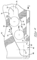
- Opposing arms 42 extend from the gripping portion 40 opposite one another to free ends 46. Disposed along each of the arms are entry openings 48 configured to receive mating lugs 68a,b ( Figure 4) that are part of the mating connector.
- the entry portion 48 is continuous with a camming slot 50 having a first end point 52 and a second end point 54 defining disengaged and engaged positions respectively.
- the second end point 54 is set further into the leg 42 than the first end point 52, when the locking lug 68a,b of the mating connector half is received within the camming slot 50 and the mating slide 38 is moved transversely, the mating connector halves are drawn together.
- the lug will travel along a lower surface 56 and when they are being disengaged, they will travel along an upper surface 58.
- Each arm 42 of the mating slide includes a pair of resilient cantilevered latches 60,62 that engage corresponding catches (not shown) on the main body portion 4 along the channels in the outer shroud 28. To establish and maintain both the locked and mated position and the unlocked position where mating and demating may occur, thereby assuring the integrity of the interconnection and that the mating slide 38 will remain within the connector assembly prior to mating in a position suitable for intermating.
- the entry portion 48 includes a mating section 64 and an exit section 66.
- a lug 68a of a mating connector half When a lug 68a of a mating connector half is received within the entry portion 48, it enters along transverse wall 70 and typically is mated by hand until initial engagement with each other. At this position, the lugs 68a would be at least above the extension of a camming surface 72 which intersects with the transverse wall 70 at point 74.
- the mating slide is then actuated in the direction of Arrow A causing the camming surface 72 to be disposed under the lug 68a.
- the camming surface 72 is disposed at angle less than the angle defined by a line extending between the first and second end points 52,54.
- This relatively shallow camming surface 72 provides mechanical advantage when the contacts and connector housings are initially being mated. The difference is made up in a steeper section 74 which has an angle greater than that defined by the end points 52,54 in order to provide the necessary displacement of the lug 68a so that it enters into the mated region 76. Obviously, it would be advantageous to provide tangential blending between the camming surface 72 and the steeper section 74 and the mated seat 76 to assure smooth operation of the mating slide.
- the camming groove 50 includes the demating surface 58.
- the demating surface 58 is a arcuate section tangential with the seat section about the second point.
- the camming lug 68b moves along the arcuate section 78 until it enters the demating portion 66 of the entry 48 where the connector halves can be separated. It is during demating, that the initial forces required are the largest. This is because it is necessary to overcome the forces associated with the static frictional forces exerted thereupon.
- the mating slide 40 includes the camming groove 50 and is transversely displaceable relative to the mating connector halves.
- the lug is fixed on the mating connector half (not shown). It would be obvious to one skilled in the art to reverse this configuration without any effect on the operability of the invention. Also more compound surfaces are envisioned as possible for the mating surface 56 and/or the demating surface 58.
- the present invention provides a camming slide/actuating slide incorporated into one connector that cooperates with a mating connector to draw the connector pair together, where a camming lug is driven along one side of a camming slot in response to mating the connectors and the camming lug is driven along another side of the camming slot in response to demating the connector pair, wherein the surfaces of the camming slot are profiled to provide the greatest mechanical advantage at the location of the largest resistance.
- the present invention may be incorporated into existing connectors.
- the present invention provides mechanical advantage for smooth operation and ease in mating.
- the present invention provides for customized mating and demating surfaces.
Landscapes
- Details Of Connecting Devices For Male And Female Coupling (AREA)
Applications Claiming Priority (2)
| Application Number | Priority Date | Filing Date | Title |
|---|---|---|---|
| GB9500374 | 1995-01-10 | ||
| GBGB9500374.5A GB9500374D0 (en) | 1995-01-10 | 1995-01-10 | Electrical connector having a mating slide with customized camming slot |
Publications (3)
| Publication Number | Publication Date |
|---|---|
| EP0722204A2 true EP0722204A2 (fr) | 1996-07-17 |
| EP0722204A3 EP0722204A3 (fr) | 1997-07-23 |
| EP0722204B1 EP0722204B1 (fr) | 2000-04-19 |
Family
ID=10767776
Family Applications (1)
| Application Number | Title | Priority Date | Filing Date |
|---|---|---|---|
| EP95119767A Expired - Lifetime EP0722204B1 (fr) | 1995-01-10 | 1995-12-14 | Connecteur électrique ayant un guide apparié avec la fente d'une came spécifique |
Country Status (6)
| Country | Link |
|---|---|
| US (1) | US5672067A (fr) |
| EP (1) | EP0722204B1 (fr) |
| JP (1) | JPH08335477A (fr) |
| KR (1) | KR960030487A (fr) |
| DE (1) | DE69516388T2 (fr) |
| GB (1) | GB9500374D0 (fr) |
Cited By (5)
| Publication number | Priority date | Publication date | Assignee | Title |
|---|---|---|---|---|
| FR2752495A1 (fr) * | 1996-08-13 | 1998-02-20 | Proner Comatel Sa | Connecteur electrique a etrier d'aide a l'insertion et de verrouillage |
| US6036509A (en) * | 1997-03-05 | 2000-03-14 | Yazaki Corporation | Low insertion force connector |
| EP0991145A3 (fr) * | 1998-09-29 | 2000-10-25 | Delphi Technologies, Inc. | Connecteur électrique en deux parties |
| FR2870648A1 (fr) * | 2004-05-18 | 2005-11-25 | Bosch Gmbh Robert | Element de fixation pour une connexion |
| WO2011120868A3 (fr) * | 2010-03-30 | 2013-02-07 | Tyco Electronics Amp Gmbh | Elément mâle avec joint de verrouillage |
Families Citing this family (12)
| Publication number | Priority date | Publication date | Assignee | Title |
|---|---|---|---|---|
| JP3326069B2 (ja) * | 1996-03-29 | 2002-09-17 | 矢崎総業株式会社 | 低挿入力コネクタ |
| US5967809A (en) * | 1996-09-23 | 1999-10-19 | General Motors Corporation | Electrical connector |
| DE29622273U1 (de) * | 1996-12-21 | 1998-04-23 | Robert Bosch Gmbh, 70469 Stuttgart | Vielpoliger elektrischer Steckverbinder |
| GB2334632B (en) * | 1998-02-23 | 2002-03-13 | Delphi Automotive Systems Gmbh | Two-part electrical connector |
| JP3412560B2 (ja) * | 1999-05-18 | 2003-06-03 | 住友電装株式会社 | コネクタ |
| JP3675242B2 (ja) | 1999-08-04 | 2005-07-27 | 矢崎総業株式会社 | 低挿入力コネクタ |
| DE10357194B4 (de) * | 2002-12-12 | 2010-04-15 | Sumitomo Wiring Systems, Ltd., Yokkaichi | Verbinderanordnung |
| JP4523987B1 (ja) * | 2009-02-27 | 2010-08-11 | タイコエレクトロニクスジャパン合同会社 | スライドカム付きコネクタ |
| US9368910B2 (en) * | 2014-08-27 | 2016-06-14 | Delphi Technologies, Inc. | Electrical connector with mechanically assisted engagement |
| EP3012922B8 (fr) * | 2014-10-20 | 2017-11-01 | Stäubli Electrical Connectors AG | Système de fermeture à levier pivotant pour système de boîtier |
| JP2018181404A (ja) | 2017-04-03 | 2018-11-15 | タイコエレクトロニクスジャパン合同会社 | 電気コネクタ |
| US11171450B2 (en) | 2019-07-12 | 2021-11-09 | International Business Machines Corporation | Method and apparatus for the alignment and locking of removable elements with a connector |
Family Cites Families (8)
| Publication number | Priority date | Publication date | Assignee | Title |
|---|---|---|---|---|
| US4586771A (en) * | 1985-03-04 | 1986-05-06 | Amp Incorporated | Connector assembly having camming system for mating and unmating |
| US4850890A (en) * | 1987-05-29 | 1989-07-25 | Yazaki Corporation | Multipolar connector |
| US5035634A (en) * | 1990-06-28 | 1991-07-30 | E. I. Du Pont De Nemours And Company | Connector inject and eject cam lever assembly |
| US5230635A (en) * | 1991-06-25 | 1993-07-27 | Yazaki Corporation | Connector with lever |
| US5474462A (en) * | 1992-05-01 | 1995-12-12 | Yazaki Corporation | Connector system with a lever requiring small force |
| GB9219328D0 (en) * | 1992-09-11 | 1992-10-28 | Amp Gmbh | Automotive door-to-body electrical |
| EP0606152B1 (fr) * | 1993-01-06 | 2000-03-15 | Sumitomo Wiring Systems, Ltd. | Connecteur à levier de verrouillage |
| GB9312513D0 (en) * | 1993-06-17 | 1993-08-04 | Amp Gmbh | Electrical connector having improved sliding cam |
-
1995
- 1995-01-10 GB GBGB9500374.5A patent/GB9500374D0/en active Pending
- 1995-12-14 DE DE69516388T patent/DE69516388T2/de not_active Expired - Lifetime
- 1995-12-14 EP EP95119767A patent/EP0722204B1/fr not_active Expired - Lifetime
- 1995-12-20 US US08/580,003 patent/US5672067A/en not_active Expired - Fee Related
-
1996
- 1996-01-06 KR KR1019960000133A patent/KR960030487A/ko not_active Withdrawn
- 1996-01-10 JP JP8020454A patent/JPH08335477A/ja active Pending
Cited By (7)
| Publication number | Priority date | Publication date | Assignee | Title |
|---|---|---|---|---|
| FR2752495A1 (fr) * | 1996-08-13 | 1998-02-20 | Proner Comatel Sa | Connecteur electrique a etrier d'aide a l'insertion et de verrouillage |
| US6036509A (en) * | 1997-03-05 | 2000-03-14 | Yazaki Corporation | Low insertion force connector |
| DE19808684C2 (de) * | 1997-03-05 | 2000-08-10 | Yazaki Corp | Leichtkraft-Steckverbindung |
| EP0991145A3 (fr) * | 1998-09-29 | 2000-10-25 | Delphi Technologies, Inc. | Connecteur électrique en deux parties |
| FR2870648A1 (fr) * | 2004-05-18 | 2005-11-25 | Bosch Gmbh Robert | Element de fixation pour une connexion |
| WO2011120868A3 (fr) * | 2010-03-30 | 2013-02-07 | Tyco Electronics Amp Gmbh | Elément mâle avec joint de verrouillage |
| US9859650B2 (en) | 2010-03-30 | 2018-01-02 | Te Connectivity Germany Gmbh | Plug element with locking seal |
Also Published As
| Publication number | Publication date |
|---|---|
| KR960030487A (ko) | 1996-08-17 |
| EP0722204A3 (fr) | 1997-07-23 |
| GB9500374D0 (en) | 1995-03-01 |
| DE69516388T2 (de) | 2000-09-21 |
| EP0722204B1 (fr) | 2000-04-19 |
| US5672067A (en) | 1997-09-30 |
| JPH08335477A (ja) | 1996-12-17 |
| DE69516388D1 (de) | 2000-05-25 |
Similar Documents
| Publication | Publication Date | Title |
|---|---|---|
| EP0722204B1 (fr) | Connecteur électrique ayant un guide apparié avec la fente d'une came spécifique | |
| US6004153A (en) | Electrical connector with connector position assurance device | |
| EP0631347B1 (fr) | Connecteur électrique ayant un organe coulissant de verouillage amélioré | |
| EP0388902B1 (fr) | Connecteur électrique ayant un système de retenue de couvercle de terminaison de câble et moyen pour atténuer l'effort de tension | |
| KR950009902B1 (ko) | 전기 커넥터 | |
| KR100363636B1 (ko) | 개선된 캠 시스템을 구비한 전기 커넥터 조립체 | |
| CA1071730A (fr) | Mecanisme de verrouillage pour conjoncteurs electriques | |
| US7252547B2 (en) | Connector | |
| EP0007709B1 (fr) | Connecteur électrique | |
| EP1343225A2 (fr) | Dispositif d'assistance de couplage pour contacts de connection électrique | |
| CA2353425C (fr) | Structure de raccordement de connecteur | |
| KR102415154B1 (ko) | 피드백을 갖는 정합 보조를 구비한 전기 커넥터 | |
| ITMI20000679U1 (it) | Connettore elettrico ad innesto con leva di manovra | |
| US5033974A (en) | Plug connector device for telecommunication and data systems | |
| EP0667654B1 (fr) | Connecteur électrique ayant un système amélioré de verrouillage et déverrouillage | |
| US6206717B1 (en) | Connector | |
| US5865636A (en) | Seal for use with an electrical connector comprising insulation displacement type contacts | |
| US5634826A (en) | Electrical connector | |
| EP0060655B1 (fr) | Assemblage de connecteurs électriques | |
| GB2300767A (en) | An electrical connector with a cam slider | |
| CN101218716B (zh) | 电连接器 | |
| EP0557976A2 (fr) | Mécanisme de verrouillage pour connecteur électrique à enfichement aveugle | |
| US4090770A (en) | Connector cover construction | |
| US10734755B2 (en) | Electrical connector and connector assembly having a seal gland | |
| EP4618320A1 (fr) | Dispositif d'assurance de position d'élément de fixation et ensemble connecteur |
Legal Events
| Date | Code | Title | Description |
|---|---|---|---|
| PUAI | Public reference made under article 153(3) epc to a published international application that has entered the european phase |
Free format text: ORIGINAL CODE: 0009012 |
|
| AK | Designated contracting states |
Kind code of ref document: A2 Designated state(s): DE ES FR GB IT NL SE |
|
| PUAL | Search report despatched |
Free format text: ORIGINAL CODE: 0009013 |
|
| AK | Designated contracting states |
Kind code of ref document: A3 Designated state(s): DE ES FR GB IT NL SE |
|
| 17P | Request for examination filed |
Effective date: 19980122 |
|
| 17Q | First examination report despatched |
Effective date: 19990428 |
|
| GRAG | Despatch of communication of intention to grant |
Free format text: ORIGINAL CODE: EPIDOS AGRA |
|
| GRAG | Despatch of communication of intention to grant |
Free format text: ORIGINAL CODE: EPIDOS AGRA |
|
| GRAH | Despatch of communication of intention to grant a patent |
Free format text: ORIGINAL CODE: EPIDOS IGRA |
|
| GRAH | Despatch of communication of intention to grant a patent |
Free format text: ORIGINAL CODE: EPIDOS IGRA |
|
| GRAA | (expected) grant |
Free format text: ORIGINAL CODE: 0009210 |
|
| AK | Designated contracting states |
Kind code of ref document: B1 Designated state(s): DE ES FR GB IT NL SE |
|
| PG25 | Lapsed in a contracting state [announced via postgrant information from national office to epo] |
Ref country code: NL Free format text: LAPSE BECAUSE OF FAILURE TO SUBMIT A TRANSLATION OF THE DESCRIPTION OR TO PAY THE FEE WITHIN THE PRESCRIBED TIME-LIMIT Effective date: 20000419 Ref country code: IT Free format text: LAPSE BECAUSE OF FAILURE TO SUBMIT A TRANSLATION OF THE DESCRIPTION OR TO PAY THE FEE WITHIN THE PRE;WARNING: LAPSES OF ITALIAN PATENTS WITH EFFECTIVE DATE BEFORE 2007 MAY HAVE OCCURRED AT ANY TIME BEFORE 2007. THE CORRECT EFFECTIVE DATE MAY BE DIFFERENT FROM THE ONE RECORDED.SCRIBED TIME-LIMIT Effective date: 20000419 Ref country code: ES Free format text: THE PATENT HAS BEEN ANNULLED BY A DECISION OF A NATIONAL AUTHORITY Effective date: 20000419 |
|
| REF | Corresponds to: |
Ref document number: 69516388 Country of ref document: DE Date of ref document: 20000525 |
|
| ET | Fr: translation filed | ||
| PG25 | Lapsed in a contracting state [announced via postgrant information from national office to epo] |
Ref country code: SE Free format text: LAPSE BECAUSE OF FAILURE TO SUBMIT A TRANSLATION OF THE DESCRIPTION OR TO PAY THE FEE WITHIN THE PRESCRIBED TIME-LIMIT Effective date: 20000719 |
|
| NLV1 | Nl: lapsed or annulled due to failure to fulfill the requirements of art. 29p and 29m of the patents act | ||
| PLBE | No opposition filed within time limit |
Free format text: ORIGINAL CODE: 0009261 |
|
| STAA | Information on the status of an ep patent application or granted ep patent |
Free format text: STATUS: NO OPPOSITION FILED WITHIN TIME LIMIT |
|
| 26N | No opposition filed | ||
| REG | Reference to a national code |
Ref country code: GB Ref legal event code: IF02 |
|
| PGFP | Annual fee paid to national office [announced via postgrant information from national office to epo] |
Ref country code: GB Payment date: 20041104 Year of fee payment: 10 |
|
| PGFP | Annual fee paid to national office [announced via postgrant information from national office to epo] |
Ref country code: FR Payment date: 20041201 Year of fee payment: 10 |
|
| PG25 | Lapsed in a contracting state [announced via postgrant information from national office to epo] |
Ref country code: GB Free format text: LAPSE BECAUSE OF NON-PAYMENT OF DUE FEES Effective date: 20051214 |
|
| GBPC | Gb: european patent ceased through non-payment of renewal fee |
Effective date: 20051214 |
|
| PG25 | Lapsed in a contracting state [announced via postgrant information from national office to epo] |
Ref country code: FR Free format text: LAPSE BECAUSE OF NON-PAYMENT OF DUE FEES Effective date: 20060831 |
|
| REG | Reference to a national code |
Ref country code: FR Ref legal event code: ST Effective date: 20060831 |
|
| PGFP | Annual fee paid to national office [announced via postgrant information from national office to epo] |
Ref country code: DE Payment date: 20141230 Year of fee payment: 20 |
|
| REG | Reference to a national code |
Ref country code: DE Ref legal event code: R071 Ref document number: 69516388 Country of ref document: DE |