EP1343225A2 - Dispositif d'assistance de couplage pour contacts de connection électrique - Google Patents
Dispositif d'assistance de couplage pour contacts de connection électrique Download PDFInfo
- Publication number
- EP1343225A2 EP1343225A2 EP03100577A EP03100577A EP1343225A2 EP 1343225 A2 EP1343225 A2 EP 1343225A2 EP 03100577 A EP03100577 A EP 03100577A EP 03100577 A EP03100577 A EP 03100577A EP 1343225 A2 EP1343225 A2 EP 1343225A2
- Authority
- EP
- European Patent Office
- Prior art keywords
- housings
- engage
- mating
- lever member
- housing
- Prior art date
- Legal status (The legal status is an assumption and is not a legal conclusion. Google has not performed a legal analysis and makes no representation as to the accuracy of the status listed.)
- Granted
Links
- 230000013011 mating Effects 0.000 claims abstract description 57
- 230000033001 locomotion Effects 0.000 claims abstract description 22
- 230000014759 maintenance of location Effects 0.000 claims description 23
- 230000002093 peripheral effect Effects 0.000 claims description 10
- 238000003780 insertion Methods 0.000 claims description 2
- 230000037431 insertion Effects 0.000 claims description 2
- 230000003068 static effect Effects 0.000 description 4
- 230000000717 retained effect Effects 0.000 description 3
- 238000001746 injection moulding Methods 0.000 description 2
- 238000004519 manufacturing process Methods 0.000 description 2
- 230000001154 acute effect Effects 0.000 description 1
- 229910003460 diamond Inorganic materials 0.000 description 1
- 239000010432 diamond Substances 0.000 description 1
- 238000000034 method Methods 0.000 description 1
Images


Classifications
-
- H—ELECTRICITY
- H01—ELECTRIC ELEMENTS
- H01R—ELECTRICALLY-CONDUCTIVE CONNECTIONS; STRUCTURAL ASSOCIATIONS OF A PLURALITY OF MUTUALLY-INSULATED ELECTRICAL CONNECTING ELEMENTS; COUPLING DEVICES; CURRENT COLLECTORS
- H01R13/00—Details of coupling devices of the kinds covered by groups H01R12/70 or H01R24/00 - H01R33/00
- H01R13/62—Means for facilitating engagement or disengagement of coupling parts or for holding them in engagement
- H01R13/629—Additional means for facilitating engagement or disengagement of coupling parts, e.g. aligning or guiding means, levers, gas pressure electrical locking indicators, manufacturing tolerances
- H01R13/62933—Comprising exclusively pivoting lever
- H01R13/62944—Pivoting lever comprising gear teeth
-
- H—ELECTRICITY
- H01—ELECTRIC ELEMENTS
- H01R—ELECTRICALLY-CONDUCTIVE CONNECTIONS; STRUCTURAL ASSOCIATIONS OF A PLURALITY OF MUTUALLY-INSULATED ELECTRICAL CONNECTING ELEMENTS; COUPLING DEVICES; CURRENT COLLECTORS
- H01R13/00—Details of coupling devices of the kinds covered by groups H01R12/70 or H01R24/00 - H01R33/00
- H01R13/62—Means for facilitating engagement or disengagement of coupling parts or for holding them in engagement
- H01R13/629—Additional means for facilitating engagement or disengagement of coupling parts, e.g. aligning or guiding means, levers, gas pressure electrical locking indicators, manufacturing tolerances
Definitions
- the present invention generally relates to a lever-based connection assembly for engaging resisting components. More particularly, invention relates to a mate assist assembly for connecting electrical contacts contained in separate housings.
- the electronic component requires the mating of several electrical contacts, such as in automotive electrical components.
- the electronic component includes a connector housing that holds several electrical contacts, while a mating connector housing holds an equal number of electrical contacts.
- One connector housing includes male electrical contacts, while the other connector housing includes female electrical contacts.
- the connector housings are formed with a mate assist assembly that includes a lever-and-gear system to pull together the connector housings in order to overcome the frictional resistance created by the mating electrical contacts.
- a mate assist assembly is described in US-A-5,833,484 that includes a lever and first and second connector housings including electrical contacts.
- the first connector housing is configured to be positioned inside the second connector housing.
- the lever includes a handle and two arms that extend from, and may be rotated alongside, end walls of the first connector housing.
- the second connector housing may be slid onto and enclose the first connector housing and the lever arms to a point where the electrical contacts resist further insertion.
- Each lever arm includes a cam arm with gear teeth.
- Racks are situated within the second connector housing with each rack corresponding to the gear teeth of one of the cam arms.
- the racks and cam arms engage and pull the first connector housing and lever downward into the second connector housing, mating the electrical contacts.
- the first connector housing is pulled upward out of the second connector housing, unmating the electrical contacts.
- the conventional mate assist assembly suffers from certain drawbacks.
- the cam arms are manufactured by the injection molding process which is difficult and time-consuming to perform when used to make a piece with many small parts such as the gear teeth.
- the multiple gear teeth are also difficult to manufacture by injection molding.
- the gear teeth do not generate a strong unmating force upon first engaging the racks. Thus, the static friction of the connected contacts is difficult to overcome. Therefore, a need exists for a mate assist assembly that overcomes the above problems and addresses other concerns experienced in the prior art.
- the present invention resides in electrical connector assembly having first and second housings.
- the first and second housings have ends configured to receive electrical contacts and have front ends configured to be matable with one another to join corresponding electrical contacts.
- the first and second housings are movable between initial and final positions, at which the corresponding electrical contacts partially and fully mate.
- the electrical connector assembly includes a lever member that engages the first and second housings and moves the first and second housings between the initial and final position as the lever member is rotated through a range of motion about a rotational axis.
- the lever member includes at least one cam arm that has a retention aperture to engage the first housing and that has first and second gear surfaces configured to engage the second housing.
- the electrical connector assembly includes first and second mating posts mounted within an interior region of the second housing.
- the first mating post engages the first gear surface at a first distance from the rotational axis as the lever member is rotating through the range of motion to move the first and second housings toward the final position.
- the second mating post engages the second gear surface at a second distance from the rotational axis as the lever is rotating an opposite direction through the range of motion to move the first and second housings toward the initial position.
- the first and the second distances are different.
- the invention resides in an electrical connector assembly having first and second housings.
- the first and second housings have ends configured to receive electrical contacts and have front ends configured to be matable with one another to join corresponding electrical contacts.
- the first and second housings are movable between initial and final positions, at which the corresponding electrical contacts partially and fully mate, respectively.
- the electrical connector assembly also includes a lever member that engages the first and second housings and moves the first and second housings between the initial and final positions as the lever member is rotated through a range of motion about a rotational axis.
- the lever member includes at least one cam arm having a retention aperture to engage the first housing and first and second unmating surfaces configured to engage the second housing.
- the electrical connector assembly also includes first and second mating posts mounted within an interior region of the second housing.
- the first mating post is configured to engage the first unmating surface a first distance from the rotational axis as the lever member is rotating through the range of motion to move the first and second housings to the initial position.
- the second mating post is configured to engage the second unmating surface a second distance from the rotational axis as the lever is rotating through the range of motion to move the first and second housings to the initial position.
- the first and second distances are different.
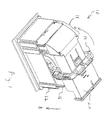
- Figure 1 illustrates a top isometric view of a mate assist assembly according to an embodiment of the present invention.
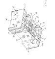
- Figure 2 illustrates an exploded isometric view of the mate assist assembly of Fig. 1.
- Figure 3 illustrates an isometric view of the bottom portion of the harness connector of Figs. 1 and 2.
- Figure 4 illustrates an isometric view of the lever member of the assembly of Fig 1.
- Figure 5 illustrates an isometric view of the module connector of Figs 1 and 2.
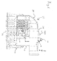
- Figure 6 illustrates a cutaway side view of the mate assist assembly of Fig. 1 in the initial staging position.
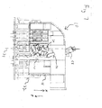
- Figure 7 illustrates a cutaway side view of the mate assist assembly of Fig. 1 in a mating stage.
- Figure 8 illustrates a cutaway side view of the mate assist assembly of Fig. 1 in the final position.
- Figure 9 illustrates a cutaway side view of the mate assist assembly of Fig. 1 in a first unmating stage.
- Figure 10 illustrates a cutaway side view of the mate assist assembly of Fig. 1 in a second unmating stage.
- Figure 11 illustrates a cutaway side view of the mate assist assembly of Fig. 1 in a final unmating stage.
- FIG. 1 illustrates a top isometric view of a mate assist assembly 10 according to an embodiment of the present invention.
- the mate assist assembly 10 includes a harness connector 18 having a bottom portion 16 and a top portion 20.
- the bottom portion 16 is configured to receive packets that hold groups of electrical contacts while the top portion 20 covers the electrical contacts.
- a module connector 22 holds electrical contacts configured to mate with the electrical contacts in the harness connector 18.
- the harness connector 18 is partially inserted within the module connector 22 to an initial staging position.
- a lever member 14 is retained on the exterior of the harness connector 18 and engages the module connector 22.
- the lever member 14 is rotatable in the direction of arrow A from the initial staging position (Fig. 1) to a final position (Fig. 8). As the lever member 14 is rotated, it pushes the harness connector 18 downward in the direction of arrow B into the module connector 22 and fully mates the electrical contacts of the harness connector 18 and the module connector 22 with each other.
- FIG. 2 illustrates an exploded isometric view of the mate assist assembly 10 of Fig. 1.
- the lever member 14 includes cam arms 26 that rotate about pivot posts 30 extending outward from the harness connector 18 along a rotational axis 36.
- the lever member 14 is oriented in an unmated position with lever arms 58 aligned generally parallel to a vertical axis 24.
- the module connector 22 includes large alignment posts 38 and a small alignment post 42 formed in the center of the module connector 22.
- the module connector 22 also includes mating posts 46 facing each other and located alongside side walls 146. Release posts 50 (only one shown) are positioned between the mating posts 46.
- each cam arm 26 is positioned between a pair of opposing mating posts 46 and above a pair of release posts 50, and the harness connector 18 slidably receives the alignment posts 38 and 42 within alignment recesses (not shown) located inside the harness connector 18.
- Figure 3 illustrates an isometric view of the bottom portion 16 of the harness connector 18 of Figs. 1 and 2.
- the bottom portion 16 is box shaped and includes the opposing side walls 60 and opposing end walls 62.
- a perimeter around the exterior of the bottom portion 16 is smaller than an interior perimeter of the module connector 22 of Figs. 1 and 2, in order that the harness connector 18 may be positioned within the module connector 22.
- Securing rails 66 and 67 extend outward from opposite ends of the side walls 60. Double securing rails 67 are located on opposite sides at one end of the bottom portion 16 and a single securing rail 67 is located on opposite sides of an opposite end of the bottom portion 16.
- the securing rails 66 and 67 are slidably received by cavities 100 (Fig. 5) within the module connector 22 so that the bottom portion 16 does not slide transversely to the securing rails 66 and 67 within the module connector 22.
- the pivot posts 30 extend outward from the centers of recessed portions 70 of the side walls 60. Each cam arm 26 (Fig. 2) encloses and rotates about a pivot post 30 along a recessed portion 70.
- the cam arms 26 are rotatable within a chamber defined by the recessed portion 70 and the module connector 22.
- the side walls 60 also include the triangular latch catches 74 that snapably engage the retention latches 56 formed with the top portion 20.
- Short securing rails 68 extend outward from the end walls 62 proximate opposite corners of the end walls 62.
- the short securing rails 68 are slidably received within the module connector 22 and engage end walls 150 (Fig. 5) of the module connector 22.
- Each end wall 62 also includes a retention wedge 78 located between two diamond shaped retention beams 82.
- the retention wedges 78 are received by retention channels 86 (Fig. 5) in the module connector 22 and snapably engage wedge catches 90 (Fig. 5) positioned within the retention channels 86.
- the retention beams 82 likewise snapably engage beam catches 94 (Fig. 5) positioned within the module connector 22.
- the retention wedges 78 and retention beams 82 slide past the wedge catches 90 and beam catches 94, respectively, so that the bottom portion 16 is retained within the module connector 22.
- the bottom portion 16 includes several connector pockets 98 of varying shapes and sizes formed with walls 99 extending from the side and end walls 60 and 62.
- the connector pockets 98 extend throughout the harness connector 16 from an open top section 102 to an open bottom section 106.
- the connector pockets 98 hold the electrical contacts that are mated with the electrical contacts contained within the module connector 22.
- Centered within the bottom portion 16 between sets of connector packets 98 is a small alignment recess 96 situated between large alignment recesses 92.
- the small and large alignment recesses 96 and 92 extend through the harness connector 16 and receive and enclose the small and large alignment posts 42 and 38 (Fig. 2) mounted in the module connector 22 when the harness connector 18 is positioned within the module connector 22.
- FIG. 4 illustrates an isometric view of the lever member 14 of Figs. 1 and 2 in more detail.
- a handle 110 is formed integral with, and extends perpendicularly between, the lever arms 58, which are in turn formed with the cam arms 26.
- Circular contact bases 114 extend along the insides of the cam arms 26, and retention apertures 118 extend through the cam arms 26 and contact bases 114.
- the lever member 14 is attached to the harness connector 18 by deflecting the lever arms 58 outward away from each other so that the contact bases 114 slide along the pivot posts 30 (Fig. 2) until the pivot posts 30 are enclosed within the retention apertures 118.
- the lever member 14 is then rotatable about the rotational axis 36 with the contact bases 114 slidably engaging the recessed portions 70 (Fig. 3) of the harness connector 18.
- the handle 110 includes two grip surfaces 122 that an operator may use to rotate the lever member 14.
- Each cam arm 26 includes a first notch 126 adjacent to a second notch 130 along a gear tooth 132 formed in the peripheral surface of the cam arm 26.
- the first notch 126 includes a first ungearing surface 134 located across from a gearing surface 138 on the gear tooth 132.
- each cam arm 26 is partially defined by a second ungearing surface 142.
- the second ungearing surfaces 142 engage the release posts 50 (Fig. 2) situated alongside the mating posts 46 as described below.
- Figure 5 illustrates an isometric view of the module connector 22 of Figs. 1 and 2.
- the two side walls 146 are formed integral with, and are aligned perpendicular to, the end walls 150.
- the side and end walls 146 and 150 are formed integral with, and extend from, a base 154, which has a larger perimeter than a perimeter about the side and end walls 146 and 150.
- the base 154 is mounted to an electronic component (not shown), such as a radio, with the side and end walls 146 and 150 extending outward from the electronic component.
- Several contact slots 158 of varying sizes and shapes extend through the base 154.
- the electrical contacts positioned within the module connector 22 are connected to the electronic component through the contact slots 158.
- the large alignment posts 38 and small alignment post 42 extend upward from the center of the base 154.
- the side walls 146 each include rail chambers 162 along the exteriors of the side walls 146 that define cavities 100 along the interiors of the side walls 146.
- the rail chambers 162 are appropriately situated along each side wall 146 so that when the harness connector 18 is positioned within the module connector 22, the cavities 100 receive corresponding securing rails 66 and 67 situated on the side walls 60 of the harness connector 18 (Fig. 3).
- the rail chambers 162 retain the securing rails 66 and 67 and guide the harness connector 18 into the module connector 22 in the proper orientation.
- the mating posts 46 and the release posts 50 extend inward from the side walls 146 along the base 154.
- Two mating posts 46 extending from one side wall 146 face each other and are oriented opposite two mating posts 46 extending from the other side wall 146.
- two release posts 50 extend from one side wall 146 between the mating posts 46 oriented opposite two release posts 50 extending from the other side wall 146.
- Each side wall 146 includes mating posts 46 and release posts 50 so that the lever member 14 and the top portion 20 (Fig. 2) of the harness connector 18 may be connected to the bottom portion 16 in either one of two orientations with each cam arm 26 still engaging a mating post 46 and a release post 50 when the harness connector 18 is inside the module connector 22.
- the mating posts 46 are rectangular in shape and include flat top surfaces 166.
- a wedge shaped tooth 170 extends from an inside wall 174 of each mating post 46 proximate the top surface 166.
- the tooth 170 includes a top portion 178 that extends downward at an acute angle from the top surface 166 to a bottom portion 182 that extends upward from, and at an obtuse angle to, the inside wall 174.
- the cam arms 26 are rotated to move the mate assist assembly 10 from the final position to the initial staging position, the first ungearing surfaces 134 (Fig. 4) engage, and are resisted by, the top portions 178, pushing the cam arms 26 upward in the direction of arrow G.
- the release posts 50 are rectangular in shape and include flat top surfaces 186 that slope downward in the direction of the other release post 50 along the same side wall 146.
- the second ungearing surfaces 142 (Fig. 4) engage, and are resisted by, the top surfaces 186, pushing the cam arms 26 upward in the direction of arrow G.
- Each end wall 150 includes two guide walls 190 that extend inwardly and perpendicularly from the end wall 150 parallel to each other.
- the two guide walls 190 and the end wall 150 define the retention channel 86 that receives a retention wedge 78 (Fig. 3).
- the beam catches 94 extend inward from the end walls 150 alongside the guide walls 190.
- the wedge catches 90 are centered between the guide walls 190 within the retention channels 86 so that the retention wedges 78 snapably slide downward past, and are retained under, the wedge catches 90 as the harness connector 18 is inserted downward into the module connector 22.
- Figure 6 illustrates a cutaway side view of the mate assist assembly 10 of Fig. 1 in the initial staging position.
- the top portion 20 includes a deflectable stop wedge 194 that extends out of a top surface 198 and is positioned to engage the handle 110 and thus prevent the lever member 14 from being rotated along the rotational axis 36 in the direction of arrow J.
- the lever arms 58 are parallel with the vertical axis 24 and the teeth 170 are partially situated within the first notches 126 and thus in the rotational path of the cam arms 26.
- the stop wedge 194 is positioned downward in the direction of arrow K so that the lever member 14 may then be rotated in the direction of arrow J about the retention axis 36 with the handle 110 passing over the deflected stop wedge 194.
- Figure 7 illustrates a cutaway side view of the mate assist assembly 10 of Fig. 1 in a mating stage.
- the lever arms 58 are at a 25-degree angle to the vertical axis 24 and the gearing surfaces 138 engage the bottom portions 182 of the teeth 170 at a first contact point 202.
- the first contact point 202 is separated from the rotational axis 36 by a distance, or pitch radius, D1.
- Figure 8 illustrates a cutaway side view of the mate assist assembly 10 of Fig. 1 in the final position.
- the lever arms 58 are horizontal, or at a 90-degree angle to the vertical axis 24.
- the electrical contacts in the harness connector 18 are fully mated with the electrical contacts in the module connector 22.
- the gearing surfaces 138 engaged the bottom portions 182 and the pivot posts 30 moved vertically downward in the direction of arrow L, the gearing surfaces 138 slid along the bottom portions 182 closer to the inside walls 174.
- an operator uses the handle 110 to rotate the lever member 14 in the direction of arrow Q about the rotational axis 36.
- Figure 9 illustrates a cutaway side view of the mate assist assembly 10 of Fig. 1 in a first unmating stage.
- the lever arms 58 are at an 80-degree angle to the vertical axis 24 and the second ungearing surfaces 142 engage the top surfaces 186 of the release posts 50 at a first contact point 220.
- the first contact point 220 is separated from the rotational axis 36 by a distance, or pitch radius, D2, which is different than D1.
- the top surfaces 186 of the release posts 50 resist the downward motions of the second ungearing surfaces 142 in the direction of arrow S, causing the cam arms 26 to pull the pivot posts 30, and thus the rotational axis 36, vertically upward in the direction of arrow T.
- the harness connector 18 is in turn pulled upward with enough force to overcome the static and the dynamic friction between the mating electrical contacts and thus partially disengage the electrical contacts.
- Figure 10 illustrates a cutaway side view of the mate assist assembly 10 of Fig. 1 in a second unmating stage.
- the lever arms 58 are at a 50-degree angle to the vertical axis 24.
- the second ungearing surfaces 142 engaged the top surfaces 186 and the pivot posts 30 were moved vertically upward in the direction of arrow Y, the second ungearing surfaces 142 slid along the top surfaces 186 toward the mating posts 46.
- the pivot posts 30 are positioned above the release posts 50 so that the second ungearing surfaces 142 no longer vertically engage the top surfaces 186 in the downward direction of arrow X and thus no longer produce a vertical vector force to disengage the electrical contents.
- the first ungearing surfaces 134 engage the top portions 178 of the teeth 170 at a first contact point 228.
- the first contact point 228 is separated from the rotational axis 36 by the distance, or pitch radius, D1.
- the top portions 178 of the teeth 170 resist the downward motions of the first ungearing surfaces 134 in the direction of arrow X, causing the cam arms 26 to pull the pivot posts 30, and thus the rotational axis 36, further vertically upward in the direction of arrow Y.
- the harness connector 18 is in turn pulled further upward with enough force to overcome the dynamic friction between the mating electrical contacts and thus fully disengage the electrical contacts.
- the handle 110 passes over, and deflects downward in the direction of arrow X, the stop wedge 194, which extends back out of the top portion 20 when the handle 110 no longer contacts the stop wedge 194.
- Figure 11 illustrates a cutaway side view of the mate assist assembly 10 of Fig. 1 in a final unmating stage.
- the lever arms 58 are once again parallel to the vertical axis 24.
- the first ungearing surfaces 134 engaged the top portions 178 and the pivot posts 30 were moved vertically upward in the direction of arrow U, the first ungearing surfaces 134 slid along the top portions 178 toward the top surfaces 166.
- the top portions 178 meet the bottom portions 182 at tips 250.
- the tips 250 are a distance D4 from the rotational axis 36.
- the distance D4 shortens so that the first ungearing surfaces 134 are in a rotational range to contact the top portions 178 as the first ungearing surfaces 134 rotate toward the top portions 178. If the rotational axis 36 did not move vertically upward closer to the tips 250, the first ungearing surfaces 134 would only laterally touch the tips 250 and no vertical forces would be created.
- the second ungearing surfaces 142 which have a pitch radius D2 (Fig. 9) that is shorter than the pitch radius D1 (Fig. 10) of the first ungearing surfaces 134, travel a first short distance to contact the release posts 50 and push the rotational axis 36 vertically upward so that the first ungearing surfaces 134 travel a second long distance to complete the unmating process without need of second cam gears engaging the teeth 170.
- the mate assist assembly confers several benefits.
- first ungearing surfaces and the gearing surfaces have a different pitch radius than the second ungearing surfaces, only one gear tooth is needed on each cam arm to engage the mating posts and the release posts in order to lift and lower the harness connector within the module connector.
- the cam arms are easier to manufacture.
- the ungearing surfaces provide enough vertical force to easily disengage the contacts.
- the second ungearing surfaces travel a short distance to engage the release posts and push down against the release posts with enough force to overcome the static friction of the mated contacts.
- the first ungearing surfaces engage the mating post with enough force to overcome the dynamic friction between the contacts and thus disengage the contacts.
Landscapes
- Details Of Connecting Devices For Male And Female Coupling (AREA)
- Coupling Device And Connection With Printed Circuit (AREA)
Applications Claiming Priority (2)
| Application Number | Priority Date | Filing Date | Title |
|---|---|---|---|
| US93345P | 2002-03-07 | ||
| US10/093,345 US6558176B1 (en) | 2002-03-07 | 2002-03-07 | Mate assist assembly for connecting electrical contacts |
Publications (3)
| Publication Number | Publication Date |
|---|---|
| EP1343225A2 true EP1343225A2 (fr) | 2003-09-10 |
| EP1343225A3 EP1343225A3 (fr) | 2004-08-25 |
| EP1343225B1 EP1343225B1 (fr) | 2010-06-23 |
Family
ID=22238413
Family Applications (1)
| Application Number | Title | Priority Date | Filing Date |
|---|---|---|---|
| EP03100577A Expired - Lifetime EP1343225B1 (fr) | 2002-03-07 | 2003-03-07 | Dispositif d'assistance de couplage pour contacts de connexion électrique |
Country Status (8)
| Country | Link |
|---|---|
| US (1) | US6558176B1 (fr) |
| EP (1) | EP1343225B1 (fr) |
| JP (1) | JP4152776B2 (fr) |
| KR (1) | KR100967793B1 (fr) |
| BR (1) | BR0300402A (fr) |
| CA (1) | CA2420961C (fr) |
| DE (1) | DE60333052D1 (fr) |
| ES (1) | ES2346417T3 (fr) |
Families Citing this family (60)
| Publication number | Priority date | Publication date | Assignee | Title |
|---|---|---|---|---|
| JP3492309B2 (ja) * | 2000-11-02 | 2004-02-03 | エフシーアイジャパン株式会社 | コネクタ |
| JP3882111B2 (ja) * | 2002-04-22 | 2007-02-14 | 住友電装株式会社 | レバー式コネクタ |
| US6881081B2 (en) * | 2002-07-31 | 2005-04-19 | Tyco Electronics Corporation | Electrical connector assembly with connection assurance features |
| US6682359B1 (en) * | 2002-12-06 | 2004-01-27 | Tyco Electronics Corporation | Electrical connector assembly with connection assurance features |
| DE102004013476A1 (de) * | 2003-04-16 | 2004-11-04 | Tyco Electronics Amp Gmbh | Steckverbinderanordnung |
| US6824406B1 (en) * | 2003-06-26 | 2004-11-30 | Delphi Technologies, Inc. | Electrical connector assembly |
| US6767231B1 (en) * | 2003-09-25 | 2004-07-27 | Tyco Electronics Corporation | Electrical connector with flexible blocking feature |
| US6971894B2 (en) * | 2004-03-31 | 2005-12-06 | Jst Corporation | Dual action mechanical assisted connector |
| US7070438B2 (en) * | 2004-03-31 | 2006-07-04 | Jst Corporation | Connector lever lock |
| DE102004018152B4 (de) * | 2004-04-08 | 2016-06-16 | Te Connectivity Germany Gmbh | Steckverbinder mit Verzahnung und Fehlsteckanschlag |
| US6899554B1 (en) | 2004-04-19 | 2005-05-31 | Jst Corporation | Dual action mechanical assisted connector |
| ATE514204T1 (de) * | 2004-08-13 | 2011-07-15 | Jst Corp | Anschluss mit hebelmechanismus mit mechanischer unterstützung |
| US7052293B2 (en) * | 2004-08-20 | 2006-05-30 | Molex Incorporated | Lever type electrical connector |
| US7255580B2 (en) * | 2005-03-09 | 2007-08-14 | Tyco Electronics Corporation | Electrical connector and electrical connector assembly having lever assist with latch hold down mechanism |
| JP2006324227A (ja) * | 2005-04-18 | 2006-11-30 | Yazaki Corp | コネクタ |
| DE102006024963B4 (de) * | 2005-05-30 | 2013-04-18 | Yazaki Corp. | Verbinder vom Hebeltyp |
| JP4579082B2 (ja) * | 2005-07-29 | 2010-11-10 | 矢崎総業株式会社 | 回転レバー式コネクタ |
| US7267564B2 (en) * | 2005-12-01 | 2007-09-11 | Molex Incorporated | Lever type electrical connector |
| JP4598681B2 (ja) * | 2006-01-17 | 2010-12-15 | 矢崎総業株式会社 | レバー嵌合式コネクタ |
| CN101427424A (zh) | 2006-02-21 | 2009-05-06 | 泰科电子公司 | 杠杆配合的连接器组件 |
| EP1997193A2 (fr) * | 2006-02-21 | 2008-12-03 | Tyco Electronics Corporation | Ensemble de connecteur a accouplement par levier |
| USD590349S1 (en) * | 2006-05-18 | 2009-04-14 | Tyco Electronics Amp K.K. | Connector housing |
| JP4884158B2 (ja) * | 2006-06-26 | 2012-02-29 | 矢崎総業株式会社 | レバー式コネクタ |
| JP4247920B2 (ja) * | 2006-10-19 | 2009-04-02 | 古河電気工業株式会社 | レバーコネクタ |
| NZ566358A (en) * | 2008-02-29 | 2010-11-26 | Fonterra Co Operative Group | Dairy product and process |
| US7726988B2 (en) * | 2008-03-26 | 2010-06-01 | Tyco Electronics Corporation | Electrical connector having disconnection assist |
| US7559779B1 (en) | 2008-05-14 | 2009-07-14 | Cinch Connectors, Inc. | Electrical connector |
| JP4515516B2 (ja) * | 2008-09-09 | 2010-08-04 | 株式会社アイペックス | コネクタ装置 |
| EP2192657A1 (fr) * | 2008-11-28 | 2010-06-02 | Tyco Electronics AMP GmbH | Connecteur de sectionnement |
| DE102009037201A1 (de) * | 2009-01-15 | 2010-07-22 | Bartec Gmbh | Elektrische Geräteeinheit |
| DE102009027660B4 (de) * | 2009-07-13 | 2015-02-05 | Tyco Electronics Amp Gmbh | Steckverbinder mit einem Sperrelement und Gehäuse mit einem Sperrelement. |
| JP5360987B2 (ja) * | 2009-09-24 | 2013-12-04 | 矢崎総業株式会社 | レバー式コネクタ |
| JP5407960B2 (ja) * | 2010-03-17 | 2014-02-05 | 住友電装株式会社 | レバー式コネクタ |
| JP5660376B2 (ja) * | 2010-12-24 | 2015-01-28 | 住友電装株式会社 | レバー付きコネクタ |
| JP5662207B2 (ja) * | 2011-03-15 | 2015-01-28 | 矢崎総業株式会社 | 嵌合補助治具 |
| JP5913874B2 (ja) * | 2011-09-12 | 2016-04-27 | 矢崎総業株式会社 | 電源回路遮断装置 |
| DE102013212914A1 (de) * | 2012-08-14 | 2014-02-20 | Robert Bosch Gmbh | Elektrisches Stecksystem |
| US9122299B2 (en) * | 2013-03-15 | 2015-09-01 | Tyco Electronics Corporation | Disconnect lever and method of manufacture |
| US9755358B2 (en) * | 2013-06-07 | 2017-09-05 | FCI Asia Pte. Ltd. | Connector assembly |
| EP3005485B1 (fr) | 2013-06-07 | 2018-01-03 | FCI Asia Pte. Ltd. | Connecteur pour cable |
| JP6099203B2 (ja) * | 2013-09-03 | 2017-03-22 | 日本航空電子工業株式会社 | コネクタ装置 |
| CN105934855B (zh) | 2013-12-03 | 2020-01-17 | 富加宜(亚洲)私人有限公司 | 连接器和用于这种连接器的插针接收接触件 |
| JP6182515B2 (ja) * | 2014-08-19 | 2017-08-16 | 日本航空電子工業株式会社 | コネクタ装置 |
| US9281614B1 (en) | 2014-10-06 | 2016-03-08 | Tyco Electronics Brasil Ltda | Connector assembly having locking members |
| EP3007283B8 (fr) * | 2014-10-07 | 2019-02-27 | Aptiv Technologies Limited | Connecteur électrique pouvant s'accoupler avec un connecteur homologue complémentaire |
| CN105914531B (zh) * | 2016-04-13 | 2019-10-11 | 河南天海电器有限公司 | 一种连接器锁紧装置 |
| DE102016120929B4 (de) * | 2016-11-03 | 2018-10-31 | Harting Electric Gmbh & Co. Kg | Verriegelungsbügel für ein Steckverbindergehäuse |
| JP6574798B2 (ja) * | 2017-02-28 | 2019-09-11 | 矢崎総業株式会社 | レバー式コネクタ |
| US10218124B1 (en) * | 2017-10-20 | 2019-02-26 | Lear Corporation | Electrical connector with terminal position assurance |
| US10181679B1 (en) * | 2017-10-20 | 2019-01-15 | Lear Corporation | Electrical connector with terminal position assurance |
| WO2019178520A1 (fr) | 2018-03-16 | 2019-09-19 | Fci Usa Llc | Connecteurs électriques à haute densité |
| US10290973B1 (en) | 2018-04-13 | 2019-05-14 | Te Connectivity Brasil Industria De Electronicos Ltda. | Lever release for lever mated connector assembly |
| FR3096839B3 (fr) * | 2019-05-31 | 2021-06-11 | Tyco Elect Suzhou Co Ltd | Boîtiers de connecteur, ensemble de boîtiers de connecteur et ensemble de connecteur |
| US11171450B2 (en) | 2019-07-12 | 2021-11-09 | International Business Machines Corporation | Method and apparatus for the alignment and locking of removable elements with a connector |
| JP7144375B2 (ja) * | 2019-07-31 | 2022-09-29 | 日本航空電子工業株式会社 | コネクタ組立体 |
| DE102019122598B4 (de) * | 2019-08-22 | 2022-09-29 | Lisa Dräxlmaier GmbH | Steckersystem zum herstellen einer elektrischen steckverbindung |
| US11381026B1 (en) * | 2020-12-29 | 2022-07-05 | Lear Corporation | Electrical connector protector plate with terminal position assurance |
| JP7591996B2 (ja) * | 2021-08-30 | 2024-11-29 | 日本航空電子工業株式会社 | コネクタ装置 |
| US12308568B2 (en) * | 2023-01-04 | 2025-05-20 | Aptiv Technologies AG | Connector assembly with flexible lock and event driven wedge |
| US20240356282A1 (en) * | 2023-04-18 | 2024-10-24 | Te Connectivity Solutions Gmbh | Lever and Header Gear Tooth Engagement to Prevent Premature Connector Mating |
Citations (2)
| Publication number | Priority date | Publication date | Assignee | Title |
|---|---|---|---|---|
| US5833484A (en) | 1995-04-21 | 1998-11-10 | The Whitaker Corporation | Connector with pivotable coupling lever |
| EP1028494A2 (fr) | 1999-02-12 | 2000-08-16 | The Whitaker Corporation | Ensemble de connecteur actionné par levier avec deux connecteurs complementaires |
Family Cites Families (15)
| Publication number | Priority date | Publication date | Assignee | Title |
|---|---|---|---|---|
| GB9203346D0 (en) * | 1992-02-17 | 1992-04-01 | Amp Gmbh | Electrical connector assembly |
| GB9402570D0 (en) | 1994-02-10 | 1994-04-06 | Amp Gmbh | Electrical connector having improved latching/unlatching feature |
| DE9411509U1 (de) * | 1994-07-15 | 1994-09-22 | Siemens AG, 80333 München | Steckverbindergehäuse |
| US5785558A (en) | 1995-11-21 | 1998-07-28 | The Whitaker Corporation | Electrical connector assembly |
| JPH09204956A (ja) * | 1996-01-26 | 1997-08-05 | Amp Japan Ltd | レバー式コネクタ |
| US6039586A (en) * | 1996-09-06 | 2000-03-21 | The Whitaker Corporation | Lever type connector |
| GB2339080A (en) * | 1998-06-29 | 2000-01-12 | Havant International Ltd | Mounting and testing of electrical devices such as disc drives |
| US6099330A (en) | 1998-07-30 | 2000-08-08 | Gundermann; James E. | Connector with lever |
| JP2000268911A (ja) * | 1999-03-08 | 2000-09-29 | Whitaker Corp:The | 電気コネクタ |
| US6368125B1 (en) * | 1999-05-18 | 2002-04-09 | Tyco Electronics Corporation | Connector with lever |
| DE19938930C1 (de) * | 1999-08-17 | 2001-04-12 | Framatome Connectors Int | Elektrischer Steckverbinder |
| JP2001076811A (ja) * | 1999-09-09 | 2001-03-23 | Sumitomo Wiring Syst Ltd | レバー式コネクタ |
| JP3493628B2 (ja) | 2001-01-18 | 2004-02-03 | 日本航空電子工業株式会社 | コネクタ装置 |
| JP2002270286A (ja) | 2001-03-13 | 2002-09-20 | Tyco Electronics Amp Kk | レバー駆動型コネクタ組立体 |
| US6736655B2 (en) | 2002-04-17 | 2004-05-18 | Tyco Electronics Corporation | Rack and pinion electrical connector with offset gear teeth |
-
2002
- 2002-03-07 US US10/093,345 patent/US6558176B1/en not_active Expired - Lifetime
-
2003
- 2003-03-06 CA CA002420961A patent/CA2420961C/fr not_active Expired - Fee Related
- 2003-03-07 JP JP2003061834A patent/JP4152776B2/ja not_active Expired - Fee Related
- 2003-03-07 ES ES03100577T patent/ES2346417T3/es not_active Expired - Lifetime
- 2003-03-07 BR BR0300402-3A patent/BR0300402A/pt not_active Application Discontinuation
- 2003-03-07 DE DE60333052T patent/DE60333052D1/de not_active Expired - Lifetime
- 2003-03-07 EP EP03100577A patent/EP1343225B1/fr not_active Expired - Lifetime
- 2003-03-07 KR KR1020030014369A patent/KR100967793B1/ko not_active Expired - Fee Related
Patent Citations (2)
| Publication number | Priority date | Publication date | Assignee | Title |
|---|---|---|---|---|
| US5833484A (en) | 1995-04-21 | 1998-11-10 | The Whitaker Corporation | Connector with pivotable coupling lever |
| EP1028494A2 (fr) | 1999-02-12 | 2000-08-16 | The Whitaker Corporation | Ensemble de connecteur actionné par levier avec deux connecteurs complementaires |
Also Published As
| Publication number | Publication date |
|---|---|
| DE60333052D1 (de) | 2010-08-05 |
| BR0300402A (pt) | 2004-08-17 |
| KR20030074311A (ko) | 2003-09-19 |
| CA2420961C (fr) | 2010-01-05 |
| ES2346417T3 (es) | 2010-10-15 |
| US6558176B1 (en) | 2003-05-06 |
| CA2420961A1 (fr) | 2003-09-07 |
| EP1343225B1 (fr) | 2010-06-23 |
| JP2003272762A (ja) | 2003-09-26 |
| JP4152776B2 (ja) | 2008-09-17 |
| EP1343225A3 (fr) | 2004-08-25 |
| KR100967793B1 (ko) | 2010-07-05 |
Similar Documents
| Publication | Publication Date | Title |
|---|---|---|
| EP1343225B1 (fr) | Dispositif d'assistance de couplage pour contacts de connexion électrique | |
| EP1320150B1 (fr) | Assemblage de connecteur électrique | |
| EP1978606B1 (fr) | Connecteur pour montage sur panneau à verrou coulissant | |
| US6736655B2 (en) | Rack and pinion electrical connector with offset gear teeth | |
| EP1361631B1 (fr) | Connecteur électrique avec engrenage à pinion et crémaillère double | |
| US5263871A (en) | Device for interconnecting connectors | |
| US6579113B2 (en) | Inertial locking connector | |
| US5273453A (en) | Electrical connector with positive latch | |
| EP1331700B1 (fr) | Dispositif d'assistance de mise en connexion pour connecteur électrique | |
| US6767231B1 (en) | Electrical connector with flexible blocking feature | |
| JPH03196478A (ja) | 電気コネクタ | |
| GB2260658A (en) | Electrical connector with module holder | |
| US5919053A (en) | Connector engaging structure | |
| KR20210001980A (ko) | 피드백을 갖는 정합 보조를 구비한 전기 커넥터 | |
| JPH04209479A (ja) | 電気コネクタ | |
| US5755587A (en) | Connector with engagement confirming mechanism | |
| US6206717B1 (en) | Connector | |
| JP2000243513A (ja) | レバー駆動型コネクタ組立体 | |
| US5975930A (en) | Slide fit connector | |
| US11695236B2 (en) | Connector assembly | |
| US5928014A (en) | Electrical connector having a pair of connector housings | |
| CN1168743A (zh) | 具有锁扣件的连接器 | |
| US20240291206A1 (en) | Connector | |
| JPH04306576A (ja) | 多極電気コネクタ |
Legal Events
| Date | Code | Title | Description |
|---|---|---|---|
| PUAI | Public reference made under article 153(3) epc to a published international application that has entered the european phase |
Free format text: ORIGINAL CODE: 0009012 |
|
| AK | Designated contracting states |
Kind code of ref document: A2 Designated state(s): AT BE BG CH CY CZ DE DK EE ES FI FR GB GR HU IE IT LI LU MC NL PT SE SI SK TR |
|
| AX | Request for extension of the european patent |
Extension state: AL LT LV MK RO |
|
| PUAL | Search report despatched |
Free format text: ORIGINAL CODE: 0009013 |
|
| AK | Designated contracting states |
Kind code of ref document: A3 Designated state(s): AT BE BG CH CY CZ DE DK EE ES FI FR GB GR HU IE IT LI LU MC NL PT SE SI SK TR |
|
| AX | Request for extension of the european patent |
Extension state: AL LT LV MK RO |
|
| 17P | Request for examination filed |
Effective date: 20050222 |
|
| AKX | Designation fees paid |
Designated state(s): DE ES FR GB IT |
|
| 17Q | First examination report despatched |
Effective date: 20081114 |
|
| GRAP | Despatch of communication of intention to grant a patent |
Free format text: ORIGINAL CODE: EPIDOSNIGR1 |
|
| GRAS | Grant fee paid |
Free format text: ORIGINAL CODE: EPIDOSNIGR3 |
|
| GRAA | (expected) grant |
Free format text: ORIGINAL CODE: 0009210 |
|
| AK | Designated contracting states |
Kind code of ref document: B1 Designated state(s): DE ES FR GB IT |
|
| REF | Corresponds to: |
Ref document number: 60333052 Country of ref document: DE Date of ref document: 20100805 Kind code of ref document: P |
|
| REG | Reference to a national code |
Ref country code: ES Ref legal event code: FG2A Ref document number: 2346417 Country of ref document: ES Kind code of ref document: T3 |
|
| PLBE | No opposition filed within time limit |
Free format text: ORIGINAL CODE: 0009261 |
|
| STAA | Information on the status of an ep patent application or granted ep patent |
Free format text: STATUS: NO OPPOSITION FILED WITHIN TIME LIMIT |
|
| 26N | No opposition filed |
Effective date: 20110324 |
|
| REG | Reference to a national code |
Ref country code: DE Ref legal event code: R097 Ref document number: 60333052 Country of ref document: DE Effective date: 20110323 |
|
| REG | Reference to a national code |
Ref country code: FR Ref legal event code: PLFP Year of fee payment: 13 |
|
| PGFP | Annual fee paid to national office [announced via postgrant information from national office to epo] |
Ref country code: ES Payment date: 20150326 Year of fee payment: 13 Ref country code: IT Payment date: 20150324 Year of fee payment: 13 |
|
| PGFP | Annual fee paid to national office [announced via postgrant information from national office to epo] |
Ref country code: GB Payment date: 20150327 Year of fee payment: 13 Ref country code: FR Payment date: 20150317 Year of fee payment: 13 |
|
| PGFP | Annual fee paid to national office [announced via postgrant information from national office to epo] |
Ref country code: DE Payment date: 20160331 Year of fee payment: 14 |
|
| GBPC | Gb: european patent ceased through non-payment of renewal fee |
Effective date: 20160307 |
|
| REG | Reference to a national code |
Ref country code: FR Ref legal event code: ST Effective date: 20161130 |
|
| PG25 | Lapsed in a contracting state [announced via postgrant information from national office to epo] |
Ref country code: GB Free format text: LAPSE BECAUSE OF NON-PAYMENT OF DUE FEES Effective date: 20160307 Ref country code: FR Free format text: LAPSE BECAUSE OF NON-PAYMENT OF DUE FEES Effective date: 20160331 |
|
| PG25 | Lapsed in a contracting state [announced via postgrant information from national office to epo] |
Ref country code: IT Free format text: LAPSE BECAUSE OF NON-PAYMENT OF DUE FEES Effective date: 20160307 |
|
| REG | Reference to a national code |
Ref country code: ES Ref legal event code: FD2A Effective date: 20170426 |
|
| PG25 | Lapsed in a contracting state [announced via postgrant information from national office to epo] |
Ref country code: ES Free format text: LAPSE BECAUSE OF NON-PAYMENT OF DUE FEES Effective date: 20160308 |
|
| REG | Reference to a national code |
Ref country code: DE Ref legal event code: R119 Ref document number: 60333052 Country of ref document: DE |
|
| PG25 | Lapsed in a contracting state [announced via postgrant information from national office to epo] |
Ref country code: DE Free format text: LAPSE BECAUSE OF NON-PAYMENT OF DUE FEES Effective date: 20171003 |