EP0722402B1 - Coupleur hydraulique pour petit moteur a entrainement direct de roue - Google Patents
Coupleur hydraulique pour petit moteur a entrainement direct de roue Download PDFInfo
- Publication number
- EP0722402B1 EP0722402B1 EP94930652A EP94930652A EP0722402B1 EP 0722402 B1 EP0722402 B1 EP 0722402B1 EP 94930652 A EP94930652 A EP 94930652A EP 94930652 A EP94930652 A EP 94930652A EP 0722402 B1 EP0722402 B1 EP 0722402B1
- Authority
- EP
- European Patent Office
- Prior art keywords
- pump
- wheel
- turbine
- fluid
- driven
- Prior art date
- Legal status (The legal status is an assumption and is not a legal conclusion. Google has not performed a legal analysis and makes no representation as to the accuracy of the status listed.)
- Expired - Lifetime
Links
- 239000012530 fluid Substances 0.000 title claims abstract description 60
- 230000008878 coupling Effects 0.000 title claims abstract description 29
- 238000010168 coupling process Methods 0.000 title claims abstract description 29
- 238000005859 coupling reaction Methods 0.000 title claims abstract description 29
- 238000001816 cooling Methods 0.000 claims abstract description 5
- 238000007789 sealing Methods 0.000 claims 1
- 238000006243 chemical reaction Methods 0.000 abstract description 3
- 239000002828 fuel tank Substances 0.000 abstract description 3
- 238000004519 manufacturing process Methods 0.000 description 1
- 230000003014 reinforcing effect Effects 0.000 description 1
Images



Classifications
-
- B—PERFORMING OPERATIONS; TRANSPORTING
- B62—LAND VEHICLES FOR TRAVELLING OTHERWISE THAN ON RAILS
- B62M—RIDER PROPULSION OF WHEELED VEHICLES OR SLEDGES; POWERED PROPULSION OF SLEDGES OR SINGLE-TRACK CYCLES; TRANSMISSIONS SPECIALLY ADAPTED FOR SUCH VEHICLES
- B62M19/00—Transmissions characterised by use of non-mechanical gearing, e.g. fluid gearing
-
- F—MECHANICAL ENGINEERING; LIGHTING; HEATING; WEAPONS; BLASTING
- F16—ENGINEERING ELEMENTS AND UNITS; GENERAL MEASURES FOR PRODUCING AND MAINTAINING EFFECTIVE FUNCTIONING OF MACHINES OR INSTALLATIONS; THERMAL INSULATION IN GENERAL
- F16D—COUPLINGS FOR TRANSMITTING ROTATION; CLUTCHES; BRAKES
- F16D33/00—Rotary fluid couplings or clutches of the hydrokinetic type
- F16D33/18—Details
Definitions
- This invention relates to a fluid coupling or torque converter for a small engine which finds use with a direct wheel drive.
- the fluid coupling of this invention can be mounted in a cantilevered support from a small engine to directly drive the rear wheel of a small scooter or alternately to a beam type support in which the outboard bearing of the fluid coupler is supported from a strut, such as a plate reinforcing gas tank mounting.
- the invention is defined by claim 1.
- a fluid coupling for the direct drive of a wheel from a small engine.
- the fluid coupling is mounted in cantilevered support or two ended bearing support from a small engine and has a small diameter inner driven shaft and a larger diameter out wheel driving shaft for contacting and directly driving a wheel.
- the inner driven shaft connects to a pump having a relatively larger outer diameter than either the driven or driving shaft.
- This pump is mounted on the opposite side of the driven wheel from the engine and preferably includes rotating vanes within one half a toroidal path having an attached eccentrically mounted toroidal plug for causing helical rotation of fluid about the plug.
- a turbine mates to the pump and includes rotating vanes within the other half of the toroidal path, these vanes being shaped around the toroidal plug of the pump.
- the toroidal plug and toroidal volumes are eccentrically mounted one with respect to another to cause high velocity flow on the outside diameter of the pump and turbine with low velocity flow in the inside diameter of the pump and turbine.
- Fluid typically oil
- a fuel tank for the engine is mounted overlying the driven wheel so as to shield the interface of the wheel and driving spindle.
- the exterior of the driven pump is supplied with vanes to generate appropriate air cooling at the fluid coupling.
- the mount of the fluid coupler includes a bearing on the outboard end of the fluid coupler.
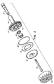
- fluid coupling C is disclosed for the direct drive of wheel W from a small engine E.
- the fluid coupling is mounted in cantilevered support from small engine E, Fig.1 showing the engine and rear end of the scooter and Fig. 2 showing wheel and engine alone.
- fluid coupling C has a small diameter inner driven shaft 14 and larger diameter outer wheel driving shaft 16 for contacting and directly driving wheel W.
- Inner driven shaft 14 connects to pump 18 having a relatively larger outer diameter than either the driven shaft 14 or driving shaft 16. Such connection occurs by bolt 15 threading to driven shaft 14. Further, it can be seen that regular ball bearing 17 and needle bearings 19 provide the necessary rotating bearings to assure transfer of the rotation.
- this pump 18 is mounted on the opposite side of the driven wheel W from engine E.
- pump 18 includes rotating vanes V P within one half a toroidal path having an attached eccentrically mounted toroidal plug P for causing helical rotation of fluid about the plug.
- Turbine T mates to pump 18 and includes rotating vanes V T within the other half of the toroidal path, these vanes being shaped around the toroidal plug P of the pump.
- toroidal plug P and toroidal volumes between vanes V P and V T are eccentrically mounted one with respect to one another. Such mounting causes high velocity flow on the outside diameter 22 of the pump and turbine with low velocity flow in the inside diameter 24 of the pump 18 and turbine 20.
- vanes V P and V T are not give arcuate configuration -- such configuration while adding to the efficiency of the disclosed fluid coupling would add undue fabrication expense. This being the case, the vanes V P and V T have walls that are essentially parallel to the axis of rotation of pump 18 and turbine 20.
- Fluid F typically oil
- Seals 30, 32 causes torque conversion between the pump and turbine.
- a fuel tank 40 for the engine is mounted overlying the driven wheel so as to shield the interface of the wheel and driving spindle.
- the exterior of the driven pump is supplied with air vanes 44 to generate appropriate air cooling at the fluid coupling.
- tank T is shown held to the side of the illustrated scooter rear wheel W at respective bolts 101, 102, 103 with appropriate washers and lock nuts.
- tank T demounts from bolts 101 - 103, it exposes plate 105.
- Plate 105 in turn has a bearing mount 110 medially of the generally triangular plate 105.
- bearing mount 110 which protrudes into and captures a bearing 120 on the outward, distal end of the fluid coupler remote from engine E.
Landscapes
- Engineering & Computer Science (AREA)
- Mechanical Engineering (AREA)
- General Engineering & Computer Science (AREA)
- Chemical & Material Sciences (AREA)
- Combustion & Propulsion (AREA)
- Transportation (AREA)
- Structures Of Non-Positive Displacement Pumps (AREA)
- Arrangement And Driving Of Transmission Devices (AREA)
- Friction Gearing (AREA)
- General Details Of Gearings (AREA)
- Hydraulic Clutches, Magnetic Clutches, Fluid Clutches, And Fluid Joints (AREA)
Claims (10)
- Ensemble composé d'une roue (W) destinée à être entraínée, d'un support de châssis de ladite roue (W) destinée à être entraínée pour tourner autour d'un axe, d'un moteur (E) monté sur ledit châssis et équipé d'un arbre de sortie sensiblement parallèle à l'axe de rotation de ladite roue (W), et, d'un coupleur hydraulique (C) connectant ladite roue (W) destinée à être entraínée et ledit moteur (E), ledit coupleur hydraulique (C) comprenant, en les combinant :caractérisé en ce que :un arbre interne mené (14) connecté audit moteur (E) sur un côté de ladite roue (W) destinée à être entraínée ;une pompe (18) connectée audit arbre mené (14) et tournant avec ledit arbre mené (14) ;du fluide dirigé vers ladite pompe (18) pour recevoir l'énergie rotationnelle en provenance dudit moteur (E) ;un arbre externe et d'entraínement de roue (16) monté concentriquement sur, et concentrique audit arbre interne mené (14) ;une turbine (20) montée sur ledit arbre externe et d'entraínement de roue (16), et juxtaposée à et communiquant par le fluide avec ladite pompe (18) du côté opposé de ladite roue (W) pour recevoir l'énergie rotationnelle transmise par ledit fluide traversant ladite pompe (18) ; et,des moyens (30, 32) de barrage du fluide entre ladite pompe (18) et ladite turbine (20) pour permettre au-fluide de circuler entre ladite pompe (18) et ladite turbine (20) pour transférer le couple entre ladite pompe (18) et ladite turbine (20) et, donc, entre l'arbre d'entrée et l'arbre de sortie (14, 16) pour l'entraínement de ladite roue (W) ;ledit arbre interne mené (14) s'étend au-delà de ladite roue (W) destinée à être entraínée, de l'autre côté de ladite roue (W) destinée à être entraínée de telle sorte que ladite pompe (18) tourné avec ledit arbre mené (14) du côté opposé de ladite roue (w) à partir du moteur (E).
- Ensemble selon la revendication 1 dans lequel ladite pompe (18) et ladite turbine (20) comprennent des ailettes (VP, VT) disposées selon un tracé torique de manière axiale autour des arbres interne et externe susmentionnés (14, 16).
- Ensemble selon la revendication 2 dans lequel les ailettes (VP, VT) sont disposées dans des plans normaux par rapport à l'axe des arbres susmentionnés (14, 16).
- Ensemble selon la revendication 1 dans lequel ladite pompe (18) comprend des ailettes (VP) disposées selon un tracé torique concentriquement autour dudit arbre interne (14), lesdites ailettes (VP) se terminant le long d'un plan normal par rapport audit arbre interne (14), sur un plan circulaire autour de ladite pompe (18) ; et
ladite turbine (20) comprend des ailettes (VT) disposées selon un tracé torique correspondant en diamètre au tracé torique de ladite pompe (18), lesdites ailettes (VT) se terminant le long d'un plan normal par rapport à l'arbre externe et d'entraínement de roue (16), sur un plan circulaire autour de ladite pompe (18), lesdites ailettes (VT) de ladite turbine (20) étant juxtaposées à et communiquant par le fluide avec lesdites ailettes (VP) de ladite pompe (18) du côté opposé de ladite roue (W) pour recevoir l'énergie rotationnelle transmise par le fluide traversant ladite pompe (18). - Ensemble selon la revendication 4, comprenant :
un bouchon torique (P) monté selon ledit tracé torique desdites ailettes (VP) de ladite pompe (18), ledit bouchon torique (P) étant disposé selon ledit tracé torique pour obliger le fluide à circuler en spirale autour dudit bouchon (P) lors du passage du fluide entre ladite pompe (18) et ladite turbine (20). - Ensemble selon la revendication 5, dans lequel :
ledit bouchon torique. (P) est adjacent audit tracé torique en certains endroits dudit tracé éloignés de l'axe dudit arbre pour obliger le fluide passant à distance de l'axe dudit arbre à circuler plus vite que le fluide passant à proximité de l'axe dudit tracé de fluide. - Ensemble selon la revendication 1, dans lequel :
des moyens formant support (17, 19, 120) destinés à soutenir ledit arbre externe et d'entraínement de roue (16) sont prévus. - Ensemble selon la revendication 1, dans lequel :ladite roue (W) est montée sur un châssis de scooter ;ladite pompe (18) a un diamètre supérieur au diamètre dudit arbre interne (14) mais inférieur au diamètre de ladite roue (W) ; etladite turbine (20) a un diamètre supérieur au diamètre dudit arbre d'entraínement (16) mais inférieur au diamètre de ladite roue entraínée (W).
- Ensemble selon la revendication 8, comprenant :
un carter autour de ladite turbine (20) destiné à tourner avec ladite turbine (20), ledit carter définissant les ailettes de refroidissement (44) sur l'extérieur de celle-ci pour faire circuler l'air durant le fonctionnement dudit coupleur hydraulique (C) et le refroidissement du fluide circulant entre ladite pompe (18) et ladite turbine (20). - Ensemble selon la revendication 8, dans lequel :
des moyens formant support (30,32) destinés à soutenir l'arbre externe et d'entraínement de roue (16) sont prévus.
Applications Claiming Priority (3)
| Application Number | Priority Date | Filing Date | Title |
|---|---|---|---|
| US136440 | 1993-10-13 | ||
| US08/136,440 US5494128A (en) | 1993-10-13 | 1993-10-13 | Fluid coupling for small engine with direct wheel drive |
| PCT/US1994/011395 WO1995010443A1 (fr) | 1993-10-13 | 1994-10-07 | Coupleur hydraulique pour petit moteur a entrainement direct de roue |
Publications (3)
| Publication Number | Publication Date |
|---|---|
| EP0722402A1 EP0722402A1 (fr) | 1996-07-24 |
| EP0722402A4 EP0722402A4 (fr) | 1998-10-14 |
| EP0722402B1 true EP0722402B1 (fr) | 2002-01-02 |
Family
ID=22472868
Family Applications (1)
| Application Number | Title | Priority Date | Filing Date |
|---|---|---|---|
| EP94930652A Expired - Lifetime EP0722402B1 (fr) | 1993-10-13 | 1994-10-07 | Coupleur hydraulique pour petit moteur a entrainement direct de roue |
Country Status (9)
| Country | Link |
|---|---|
| US (1) | US5494128A (fr) |
| EP (1) | EP0722402B1 (fr) |
| JP (1) | JPH09505782A (fr) |
| AT (1) | ATE211449T1 (fr) |
| DE (1) | DE69429581T2 (fr) |
| DK (1) | DK0722402T3 (fr) |
| ES (1) | ES2166380T3 (fr) |
| PT (1) | PT722402E (fr) |
| WO (1) | WO1995010443A1 (fr) |
Families Citing this family (12)
| Publication number | Priority date | Publication date | Assignee | Title |
|---|---|---|---|---|
| JPS62279954A (ja) | 1986-05-29 | 1987-12-04 | Canon Inc | インクジエツト記録方法 |
| US5491390A (en) * | 1994-01-18 | 1996-02-13 | Mcgreen; James R. | Electric propulsion system for a bicycle |
| US5660242A (en) * | 1995-11-21 | 1997-08-26 | Patmont Motor Werks | Self starting and braking clutch for fluid coupling for small engine with direct wheel drive |
| US5791948A (en) * | 1997-07-03 | 1998-08-11 | Lecompte; Dale | Outboard air drive system |
| US6095274A (en) * | 1998-04-09 | 2000-08-01 | Patmont; Steven J. | Engine drive for scooter |
| US6012539A (en) * | 1998-05-01 | 2000-01-11 | Patmont Motor Werks | All terrain scooter |
| US6347681B1 (en) | 1999-08-27 | 2002-02-19 | Patmont Motor Werks | Electrically integrated scooter with dual suspension and stowage mechanism |
| AU2003210476A1 (en) * | 2002-01-10 | 2003-07-30 | Sbs Enterprises, Llc | Scooter drive device |
| USD486761S1 (en) | 2002-03-19 | 2004-02-17 | Sbs Enterprises, Llc | Ornamental housing |
| ES2335810T3 (es) * | 2006-12-01 | 2010-04-05 | Cakir Aga Motorlu Tasitlar Sanayi Ve Ticaret Ltd. Sti. | Transmision de accionamiento directo de velocidad variable. |
| USD563484S1 (en) | 2006-12-04 | 2008-03-04 | Kj's Inc. | Motor scooter |
| US10247193B2 (en) | 2013-09-09 | 2019-04-02 | United Technologies Corporation | Reservoir egress fluid coupler |
Family Cites Families (11)
| Publication number | Priority date | Publication date | Assignee | Title |
|---|---|---|---|---|
| DE38779C (de) * | E. BRUHN in Kopenhagen, Frederiksbergade Nr. 16 | Selbststeuerndes Angelflofs, an welchem auch Köder oder Lockmittel für die Wasserjagd angebracht werden können | ||
| FR954847A (fr) * | 1950-01-06 | |||
| US2115895A (en) * | 1934-05-14 | 1938-05-03 | Chrysler Corp | Power transmitting device |
| US2139107A (en) * | 1936-10-28 | 1938-12-06 | American Blower Corp | Hydraulic coupling |
| US2294994A (en) * | 1940-09-26 | 1942-09-08 | C E Miller Mfg Corp | Fluid drive for motorcycles |
| FR930989A (fr) * | 1941-11-04 | 1948-02-10 | App Control Equip Moteurs | Perfectionnements apportés aux dispositifs d'entraînement auxiliaires par moteur pour des véhicules légers |
| FR992450A (fr) * | 1949-05-25 | 1951-10-18 | Const Mecaniques Soc Gen Franc | Bâti-support pour moteur auxiliaire de bicyclette |
| US2663149A (en) * | 1950-12-30 | 1953-12-22 | Borg Warner | Rotary turbine-type hydraulic torque converter |
| US2998782A (en) * | 1958-11-26 | 1961-09-05 | American Radiator & Standard | Fluid drive rotor vane tie ring |
| US3339659A (en) * | 1965-11-22 | 1967-09-05 | Walter A Wolf | Powered friction-driving device for vehicles |
| US4821832A (en) * | 1987-07-09 | 1989-04-18 | Patmont Steven J | Motor scooter having a foldable handle and friction drive |
-
1993
- 1993-10-13 US US08/136,440 patent/US5494128A/en not_active Expired - Fee Related
-
1994
- 1994-10-07 DE DE69429581T patent/DE69429581T2/de not_active Expired - Fee Related
- 1994-10-07 JP JP7511927A patent/JPH09505782A/ja active Pending
- 1994-10-07 WO PCT/US1994/011395 patent/WO1995010443A1/fr not_active Ceased
- 1994-10-07 EP EP94930652A patent/EP0722402B1/fr not_active Expired - Lifetime
- 1994-10-07 DK DK94930652T patent/DK0722402T3/da active
- 1994-10-07 ES ES94930652T patent/ES2166380T3/es not_active Expired - Lifetime
- 1994-10-07 PT PT94930652T patent/PT722402E/pt unknown
- 1994-10-07 AT AT94930652T patent/ATE211449T1/de not_active IP Right Cessation
Also Published As
| Publication number | Publication date |
|---|---|
| US5494128A (en) | 1996-02-27 |
| ES2166380T3 (es) | 2002-04-16 |
| DK0722402T3 (da) | 2002-03-18 |
| ATE211449T1 (de) | 2002-01-15 |
| EP0722402A1 (fr) | 1996-07-24 |
| EP0722402A4 (fr) | 1998-10-14 |
| WO1995010443A1 (fr) | 1995-04-20 |
| DE69429581D1 (de) | 2002-02-07 |
| PT722402E (pt) | 2002-06-28 |
| DE69429581T2 (de) | 2002-08-08 |
| JPH09505782A (ja) | 1997-06-10 |
Similar Documents
| Publication | Publication Date | Title |
|---|---|---|
| US5494128A (en) | Fluid coupling for small engine with direct wheel drive | |
| US6398521B1 (en) | Adapter for motor and fluid pump | |
| AU597276B2 (en) | Electric wheel drive | |
| EP0573844B1 (fr) | Entraînement hydrostatique du type "transaxle" avec un carter d'engrenage perfectionné | |
| JP3367582B2 (ja) | 車両の動力伝達装置 | |
| US4257370A (en) | Combined gear cover and mount for an internal combustion engine | |
| RU2001122811A (ru) | Гидродинамическая муфта | |
| US20230105272A1 (en) | Drive assembly and vehicle | |
| US4640153A (en) | Accessory drive for a turbine engine | |
| US7302873B2 (en) | Angle drive with power distribution | |
| JPH07305685A (ja) | 回転歯車装置 | |
| FR2566085A1 (fr) | Engrenage planetaire avec pompe de lubrification | |
| JPH0233401A (ja) | 翼車軸の軸受構造 | |
| CN201373081Y (zh) | 一种新型双涡轮液力变矩器 | |
| CN100460718C (zh) | 行星齿轮减速器和摆线液压马达的组合装置 | |
| CN101418802A (zh) | 水泵 | |
| FR2706969A1 (fr) | ||
| EP4048897A1 (fr) | Turbomachine munie d'une pompe electromagnetique a flux magnetique axial | |
| CN218235340U (zh) | 一种轴配流摆线液压马达 | |
| CN214355366U (zh) | 驱动桥半轴 | |
| US2304336A (en) | Hydraulic coupling | |
| JP3963836B2 (ja) | 環状ハウジングを備えたアングル駆動装置 | |
| AU726037B2 (en) | Power transmission line and hydrodynamic coupling modular unit for integration into a power transmission unit | |
| CN220956629U (zh) | 一种起重机用输出轴双轴承支撑取力器 | |
| CN217633675U (zh) | 一种轴端传动安装结构 |
Legal Events
| Date | Code | Title | Description |
|---|---|---|---|
| PUAI | Public reference made under article 153(3) epc to a published international application that has entered the european phase |
Free format text: ORIGINAL CODE: 0009012 |
|
| 17P | Request for examination filed |
Effective date: 19960513 |
|
| AK | Designated contracting states |
Kind code of ref document: A1 Designated state(s): AT BE CH DE DK ES FR GB GR IE IT LI LU MC NL PT SE |
|
| RHK1 | Main classification (correction) |
Ipc: B62M 13/00 |
|
| A4 | Supplementary search report drawn up and despatched |
Effective date: 19980811 |
|
| AK | Designated contracting states |
Kind code of ref document: A4 Designated state(s): AT BE CH DE DK ES FR GB GR IE IT LI LU MC NL PT SE |
|
| 17Q | First examination report despatched |
Effective date: 19990518 |
|
| GRAG | Despatch of communication of intention to grant |
Free format text: ORIGINAL CODE: EPIDOS AGRA |
|
| GRAG | Despatch of communication of intention to grant |
Free format text: ORIGINAL CODE: EPIDOS AGRA |
|
| GRAH | Despatch of communication of intention to grant a patent |
Free format text: ORIGINAL CODE: EPIDOS IGRA |
|
| GRAH | Despatch of communication of intention to grant a patent |
Free format text: ORIGINAL CODE: EPIDOS IGRA |
|
| GRAA | (expected) grant |
Free format text: ORIGINAL CODE: 0009210 |
|
| REG | Reference to a national code |
Ref country code: GB Ref legal event code: IF02 |
|
| AK | Designated contracting states |
Kind code of ref document: B1 Designated state(s): AT BE CH DE DK ES FR GB GR IE IT LI LU MC NL PT SE |
|
| REF | Corresponds to: |
Ref document number: 211449 Country of ref document: AT Date of ref document: 20020115 Kind code of ref document: T |
|
| REG | Reference to a national code |
Ref country code: CH Ref legal event code: EP |
|
| REG | Reference to a national code |
Ref country code: IE Ref legal event code: FG4D |
|
| REF | Corresponds to: |
Ref document number: 69429581 Country of ref document: DE Date of ref document: 20020207 |
|
| REG | Reference to a national code |
Ref country code: DK Ref legal event code: T3 |
|
| ET | Fr: translation filed | ||
| REG | Reference to a national code |
Ref country code: ES Ref legal event code: FG2A Ref document number: 2166380 Country of ref document: ES Kind code of ref document: T3 |
|
| REG | Reference to a national code |
Ref country code: PT Ref legal event code: SC4A Free format text: AVAILABILITY OF NATIONAL TRANSLATION Effective date: 20020322 |
|
| REG | Reference to a national code |
Ref country code: GR Ref legal event code: EP Ref document number: 20020401283 Country of ref document: GR |
|
| PG25 | Lapsed in a contracting state [announced via postgrant information from national office to epo] |
Ref country code: LU Free format text: LAPSE BECAUSE OF NON-PAYMENT OF DUE FEES Effective date: 20021007 Ref country code: IE Free format text: LAPSE BECAUSE OF NON-PAYMENT OF DUE FEES Effective date: 20021007 Ref country code: GB Free format text: LAPSE BECAUSE OF NON-PAYMENT OF DUE FEES Effective date: 20021007 Ref country code: AT Free format text: LAPSE BECAUSE OF NON-PAYMENT OF DUE FEES Effective date: 20021007 |
|
| PG25 | Lapsed in a contracting state [announced via postgrant information from national office to epo] |
Ref country code: SE Free format text: LAPSE BECAUSE OF NON-PAYMENT OF DUE FEES Effective date: 20021008 Ref country code: ES Free format text: LAPSE BECAUSE OF NON-PAYMENT OF DUE FEES Effective date: 20021008 |
|
| PG25 | Lapsed in a contracting state [announced via postgrant information from national office to epo] |
Ref country code: LI Free format text: LAPSE BECAUSE OF NON-PAYMENT OF DUE FEES Effective date: 20021031 Ref country code: DK Free format text: LAPSE BECAUSE OF NON-PAYMENT OF DUE FEES Effective date: 20021031 Ref country code: CH Free format text: LAPSE BECAUSE OF NON-PAYMENT OF DUE FEES Effective date: 20021031 Ref country code: BE Free format text: LAPSE BECAUSE OF NON-PAYMENT OF DUE FEES Effective date: 20021031 |
|
| PLBE | No opposition filed within time limit |
Free format text: ORIGINAL CODE: 0009261 |
|
| STAA | Information on the status of an ep patent application or granted ep patent |
Free format text: STATUS: NO OPPOSITION FILED WITHIN TIME LIMIT |
|
| 26N | No opposition filed | ||
| BERE | Be: lapsed |
Owner name: *PATMONT MOTOR WERKS INC. Effective date: 20021031 |
|
| PG25 | Lapsed in a contracting state [announced via postgrant information from national office to epo] |
Ref country code: PT Free format text: LAPSE BECAUSE OF NON-PAYMENT OF DUE FEES Effective date: 20030430 |
|
| PG25 | Lapsed in a contracting state [announced via postgrant information from national office to epo] |
Ref country code: NL Free format text: LAPSE BECAUSE OF NON-PAYMENT OF DUE FEES Effective date: 20030501 Ref country code: MC Free format text: LAPSE BECAUSE OF NON-PAYMENT OF DUE FEES Effective date: 20030501 Ref country code: DE Free format text: LAPSE BECAUSE OF NON-PAYMENT OF DUE FEES Effective date: 20030501 |
|
| GBPC | Gb: european patent ceased through non-payment of renewal fee |
Effective date: 20021007 |
|
| EUG | Se: european patent has lapsed | ||
| REG | Reference to a national code |
Ref country code: DK Ref legal event code: EBP |
|
| REG | Reference to a national code |
Ref country code: CH Ref legal event code: PL |
|
| PG25 | Lapsed in a contracting state [announced via postgrant information from national office to epo] |
Ref country code: FR Free format text: LAPSE BECAUSE OF NON-PAYMENT OF DUE FEES Effective date: 20030630 |
|
| NLV4 | Nl: lapsed or anulled due to non-payment of the annual fee |
Effective date: 20030501 |
|
| REG | Reference to a national code |
Ref country code: IE Ref legal event code: MM4A |
|
| REG | Reference to a national code |
Ref country code: FR Ref legal event code: ST |
|
| REG | Reference to a national code |
Ref country code: ES Ref legal event code: FD2A Effective date: 20031112 |
|
| PG25 | Lapsed in a contracting state [announced via postgrant information from national office to epo] |
Ref country code: GR Free format text: LAPSE BECAUSE OF NON-PAYMENT OF DUE FEES Effective date: 20040504 |
|
| PG25 | Lapsed in a contracting state [announced via postgrant information from national office to epo] |
Ref country code: IT Free format text: LAPSE BECAUSE OF NON-PAYMENT OF DUE FEES;WARNING: LAPSES OF ITALIAN PATENTS WITH EFFECTIVE DATE BEFORE 2007 MAY HAVE OCCURRED AT ANY TIME BEFORE 2007. THE CORRECT EFFECTIVE DATE MAY BE DIFFERENT FROM THE ONE RECORDED. Effective date: 20051007 |
|
| PG25 | Lapsed in a contracting state [announced via postgrant information from national office to epo] |
Ref country code: GR Free format text: LAPSE BECAUSE OF NON-PAYMENT OF DUE FEES Effective date: 20020102 |