EP0722576B1 - Lichtquelle für hintergrundsbeleuchtung - Google Patents
Lichtquelle für hintergrundsbeleuchtung Download PDFInfo
- Publication number
- EP0722576B1 EP0722576B1 EP94931796A EP94931796A EP0722576B1 EP 0722576 B1 EP0722576 B1 EP 0722576B1 EP 94931796 A EP94931796 A EP 94931796A EP 94931796 A EP94931796 A EP 94931796A EP 0722576 B1 EP0722576 B1 EP 0722576B1
- Authority
- EP
- European Patent Office
- Prior art keywords
- aperture
- cavity
- light
- display panel
- light source
- Prior art date
- Legal status (The legal status is an assumption and is not a legal conclusion. Google has not performed a legal analysis and makes no representation as to the accuracy of the status listed.)
- Expired - Lifetime
Links
- 230000002708 enhancing effect Effects 0.000 claims abstract description 13
- 238000005286 illumination Methods 0.000 claims description 23
- 239000000463 material Substances 0.000 claims description 12
- 239000012141 concentrate Substances 0.000 claims description 9
- 239000003973 paint Substances 0.000 claims description 6
- 238000000034 method Methods 0.000 claims description 5
- 239000004033 plastic Substances 0.000 claims description 4
- 239000010408 film Substances 0.000 description 12
- 230000000694 effects Effects 0.000 description 4
- 238000002310 reflectometry Methods 0.000 description 4
- 230000005540 biological transmission Effects 0.000 description 3
- 230000007423 decrease Effects 0.000 description 3
- GWEVSGVZZGPLCZ-UHFFFAOYSA-N Titan oxide Chemical compound O=[Ti]=O GWEVSGVZZGPLCZ-UHFFFAOYSA-N 0.000 description 2
- 239000011248 coating agent Substances 0.000 description 2
- 238000000576 coating method Methods 0.000 description 2
- 239000003086 colorant Substances 0.000 description 2
- 210000000887 face Anatomy 0.000 description 2
- 210000003128 head Anatomy 0.000 description 2
- 239000004973 liquid crystal related substance Substances 0.000 description 2
- 238000010521 absorption reaction Methods 0.000 description 1
- 230000008859 change Effects 0.000 description 1
- 238000010276 construction Methods 0.000 description 1
- 239000002537 cosmetic Substances 0.000 description 1
- 238000012423 maintenance Methods 0.000 description 1
- 230000003287 optical effect Effects 0.000 description 1
- 239000004417 polycarbonate Substances 0.000 description 1
- 229920000515 polycarbonate Polymers 0.000 description 1
- 230000005855 radiation Effects 0.000 description 1
- 230000004044 response Effects 0.000 description 1
- 238000000926 separation method Methods 0.000 description 1
- 230000003595 spectral effect Effects 0.000 description 1
- 230000007480 spreading Effects 0.000 description 1
- 239000010409 thin film Substances 0.000 description 1
- 238000002834 transmittance Methods 0.000 description 1
Images


Classifications
-
- G—PHYSICS
- G02—OPTICS
- G02F—OPTICAL DEVICES OR ARRANGEMENTS FOR THE CONTROL OF LIGHT BY MODIFICATION OF THE OPTICAL PROPERTIES OF THE MEDIA OF THE ELEMENTS INVOLVED THEREIN; NON-LINEAR OPTICS; FREQUENCY-CHANGING OF LIGHT; OPTICAL LOGIC ELEMENTS; OPTICAL ANALOGUE/DIGITAL CONVERTERS
- G02F1/00—Devices or arrangements for the control of the intensity, colour, phase, polarisation or direction of light arriving from an independent light source, e.g. switching, gating or modulating; Non-linear optics
- G02F1/01—Devices or arrangements for the control of the intensity, colour, phase, polarisation or direction of light arriving from an independent light source, e.g. switching, gating or modulating; Non-linear optics for the control of the intensity, phase, polarisation or colour
- G02F1/13—Devices or arrangements for the control of the intensity, colour, phase, polarisation or direction of light arriving from an independent light source, e.g. switching, gating or modulating; Non-linear optics for the control of the intensity, phase, polarisation or colour based on liquid crystals, e.g. single liquid crystal display cells
- G02F1/133—Constructional arrangements; Operation of liquid crystal cells; Circuit arrangements
- G02F1/1333—Constructional arrangements; Manufacturing methods
- G02F1/1337—Surface-induced orientation of the liquid crystal molecules, e.g. by alignment layers
-
- F—MECHANICAL ENGINEERING; LIGHTING; HEATING; WEAPONS; BLASTING
- F21—LIGHTING
- F21S—NON-PORTABLE LIGHTING DEVICES; SYSTEMS THEREOF; VEHICLE LIGHTING DEVICES SPECIALLY ADAPTED FOR VEHICLE EXTERIORS
- F21S8/00—Lighting devices intended for fixed installation
-
- F—MECHANICAL ENGINEERING; LIGHTING; HEATING; WEAPONS; BLASTING
- F21—LIGHTING
- F21V—FUNCTIONAL FEATURES OR DETAILS OF LIGHTING DEVICES OR SYSTEMS THEREOF; STRUCTURAL COMBINATIONS OF LIGHTING DEVICES WITH OTHER ARTICLES, NOT OTHERWISE PROVIDED FOR
- F21V7/00—Reflectors for light sources
-
- G—PHYSICS
- G02—OPTICS
- G02F—OPTICAL DEVICES OR ARRANGEMENTS FOR THE CONTROL OF LIGHT BY MODIFICATION OF THE OPTICAL PROPERTIES OF THE MEDIA OF THE ELEMENTS INVOLVED THEREIN; NON-LINEAR OPTICS; FREQUENCY-CHANGING OF LIGHT; OPTICAL LOGIC ELEMENTS; OPTICAL ANALOGUE/DIGITAL CONVERTERS
- G02F1/00—Devices or arrangements for the control of the intensity, colour, phase, polarisation or direction of light arriving from an independent light source, e.g. switching, gating or modulating; Non-linear optics
- G02F1/01—Devices or arrangements for the control of the intensity, colour, phase, polarisation or direction of light arriving from an independent light source, e.g. switching, gating or modulating; Non-linear optics for the control of the intensity, phase, polarisation or colour
- G02F1/13—Devices or arrangements for the control of the intensity, colour, phase, polarisation or direction of light arriving from an independent light source, e.g. switching, gating or modulating; Non-linear optics for the control of the intensity, phase, polarisation or colour based on liquid crystals, e.g. single liquid crystal display cells
- G02F1/133—Constructional arrangements; Operation of liquid crystal cells; Circuit arrangements
- G02F1/1333—Constructional arrangements; Manufacturing methods
- G02F1/1335—Structural association of cells with optical devices, e.g. polarisers or reflectors
- G02F1/1336—Illuminating devices
- G02F1/133615—Edge-illuminating devices, i.e. illuminating from the side
-
- F—MECHANICAL ENGINEERING; LIGHTING; HEATING; WEAPONS; BLASTING
- F21—LIGHTING
- F21Y—INDEXING SCHEME ASSOCIATED WITH SUBCLASSES F21K, F21L, F21S and F21V, RELATING TO THE FORM OR THE KIND OF THE LIGHT SOURCES OR OF THE COLOUR OF THE LIGHT EMITTED
- F21Y2115/00—Light-generating elements of semiconductor light sources
- F21Y2115/10—Light-emitting diodes [LED]
-
- G—PHYSICS
- G02—OPTICS
- G02B—OPTICAL ELEMENTS, SYSTEMS OR APPARATUS
- G02B6/00—Light guides; Structural details of arrangements comprising light guides and other optical elements, e.g. couplings
- G02B6/0001—Light guides; Structural details of arrangements comprising light guides and other optical elements, e.g. couplings specially adapted for lighting devices or systems
- G02B6/0011—Light guides; Structural details of arrangements comprising light guides and other optical elements, e.g. couplings specially adapted for lighting devices or systems the light guides being planar or of plate-like form
- G02B6/0033—Means for improving the coupling-out of light from the light guide
- G02B6/005—Means for improving the coupling-out of light from the light guide provided by one optical element, or plurality thereof, placed on the light output side of the light guide
- G02B6/0053—Prismatic sheet or layer; Brightness enhancement element, sheet or layer
-
- G—PHYSICS
- G02—OPTICS
- G02B—OPTICAL ELEMENTS, SYSTEMS OR APPARATUS
- G02B6/00—Light guides; Structural details of arrangements comprising light guides and other optical elements, e.g. couplings
- G02B6/0001—Light guides; Structural details of arrangements comprising light guides and other optical elements, e.g. couplings specially adapted for lighting devices or systems
- G02B6/0011—Light guides; Structural details of arrangements comprising light guides and other optical elements, e.g. couplings specially adapted for lighting devices or systems the light guides being planar or of plate-like form
- G02B6/0033—Means for improving the coupling-out of light from the light guide
- G02B6/005—Means for improving the coupling-out of light from the light guide provided by one optical element, or plurality thereof, placed on the light output side of the light guide
- G02B6/0055—Reflecting element, sheet or layer
-
- G—PHYSICS
- G02—OPTICS
- G02F—OPTICAL DEVICES OR ARRANGEMENTS FOR THE CONTROL OF LIGHT BY MODIFICATION OF THE OPTICAL PROPERTIES OF THE MEDIA OF THE ELEMENTS INVOLVED THEREIN; NON-LINEAR OPTICS; FREQUENCY-CHANGING OF LIGHT; OPTICAL LOGIC ELEMENTS; OPTICAL ANALOGUE/DIGITAL CONVERTERS
- G02F1/00—Devices or arrangements for the control of the intensity, colour, phase, polarisation or direction of light arriving from an independent light source, e.g. switching, gating or modulating; Non-linear optics
- G02F1/01—Devices or arrangements for the control of the intensity, colour, phase, polarisation or direction of light arriving from an independent light source, e.g. switching, gating or modulating; Non-linear optics for the control of the intensity, phase, polarisation or colour
- G02F1/13—Devices or arrangements for the control of the intensity, colour, phase, polarisation or direction of light arriving from an independent light source, e.g. switching, gating or modulating; Non-linear optics for the control of the intensity, phase, polarisation or colour based on liquid crystals, e.g. single liquid crystal display cells
- G02F1/133—Constructional arrangements; Operation of liquid crystal cells; Circuit arrangements
- G02F1/1333—Constructional arrangements; Manufacturing methods
- G02F1/1335—Structural association of cells with optical devices, e.g. polarisers or reflectors
- G02F1/133504—Diffusing, scattering, diffracting elements
- G02F1/133507—Films for enhancing the luminance
-
- G—PHYSICS
- G02—OPTICS
- G02F—OPTICAL DEVICES OR ARRANGEMENTS FOR THE CONTROL OF LIGHT BY MODIFICATION OF THE OPTICAL PROPERTIES OF THE MEDIA OF THE ELEMENTS INVOLVED THEREIN; NON-LINEAR OPTICS; FREQUENCY-CHANGING OF LIGHT; OPTICAL LOGIC ELEMENTS; OPTICAL ANALOGUE/DIGITAL CONVERTERS
- G02F1/00—Devices or arrangements for the control of the intensity, colour, phase, polarisation or direction of light arriving from an independent light source, e.g. switching, gating or modulating; Non-linear optics
- G02F1/01—Devices or arrangements for the control of the intensity, colour, phase, polarisation or direction of light arriving from an independent light source, e.g. switching, gating or modulating; Non-linear optics for the control of the intensity, phase, polarisation or colour
- G02F1/13—Devices or arrangements for the control of the intensity, colour, phase, polarisation or direction of light arriving from an independent light source, e.g. switching, gating or modulating; Non-linear optics for the control of the intensity, phase, polarisation or colour based on liquid crystals, e.g. single liquid crystal display cells
- G02F1/133—Constructional arrangements; Operation of liquid crystal cells; Circuit arrangements
- G02F1/1333—Constructional arrangements; Manufacturing methods
- G02F1/1335—Structural association of cells with optical devices, e.g. polarisers or reflectors
- G02F1/1336—Illuminating devices
- G02F1/133602—Direct backlight
- G02F1/133605—Direct backlight including specially adapted reflectors
Definitions
- the present invention relates to a backlighting apparatus for displays, particularly for small-area liquid-crystal displays (LCDs), such as utilized in virtual reality headsets.
- LCDs which allow the display of alphanumeric, graphic or other information, may comprise a medium whose transmittance changes in response to the application of an electrical potential across the medium.
- the LCDs may be viewed even in an otherwise dark environment by applying illumination uniformly to their rear face.
- An exemplary backlighting apparatus for an LCD is disclosed in U.S. Patent 4,043,636.
- a backlight for small-area LCDs such as those found in helmets of virtual reality systems, to have certain attributes. Firstly, it must have an acceptable level of brightness. Secondly, it is preferable to have a spectral distribution that is as white as possible, particularly if the LCDs display color images.
- the light source must be compact, and preferably require little maintenance.
- the lighting system must provide uniform illumination across the entire area of the display. This latter need translates into a requirement that the light emerging from the light source be featureless and free of distortions such as holes or rings. In practice, the requirement of uniform illumination is difficult to achieve, and prior art devices frequently fail to provide a sufficiently uniform source of illumination for LCD displays. Additionally, prior art devices frequently relied on light guides to direct light to reflective surfaces, necessitating complicated geometries and added weight and expense.
- An object of the present invention is therefore to provide a simple, compact, lightweight means for backlighting a display, typically a small-area LCD display, which provides highly uniform, high-intensity illumination of the entire display panel.
- US 5,128,783 A shows that it has been attempted to incorporate both a discrete light diffuser and a discrete light collimator into the same backlit liquid crystal apparatus and that it was necessary to operatively space the diffuser from the light source and from the display panel, thereby eliminating one of the principle advantages of flat display panels, i.e. compactness.
- US 5,128,783 A proposed a technique which involves a combination of a lighting configuration with a diffusing/collimating lens which is formed as an integral unit and discloses that there must exist a correspondence in shape between that of the lighting configuration and that of the diffusing/collimating lens array.
- the light source of the present invention backlights a rear surface of a display panel, and includes a housing having diffusely reflective interior surfaces which form a cavity.
- a device that emits light for example, an incandescent light bulb or LED array, is mounted in the cavity with the interior surfaces of the cavity spaced therefrom.
- the housing has an aperture juxtaposed with the rear surface of the display panel which opens into the cavity.
- the ratio of the area of the aperture to the sum of (i) the area of said aperture and (ii) the diffusely reflective surface area of the cavity is at least 0.05 in a preferred embodiment of the present invention.
- the ratio of the depth of the cavity to an edge to edge dimension of the aperture is at least 0.1.
- the aperture of the embodiment disclosed also has a bisector dimension, defined as the edge-to-edge length of the aperture along a line formed by the intersection of the plane of the aperture and a plane normal to the plane of the aperture extending through the bulb and bisecting the aperture.
- the ratio of the depth of the cavity to its bisector dimension is at least 0.1 in a preferred embodiment of the present invention. In one embodiment of the present invention, the depth of the cavity is not substantially greater than the diameter of the envelope of the light bulb.
- the light source also comprises a diffuser placed across the aperture and positioned to diffuse illumination which passes through the aperture from the cavity toward the display panel.
- a brightness enhancing material for passing illumination within a viewing range is disposed between the diffuser and the display panel.
- the viewing range is 50 degrees. This range is the sum of a pair of angles of 25 degrees measured relative to lines normal to the plane of the aperture.
- a color filter may be included between the cavity and the LCD.
- the filter is placed between the brightness enhancing film (BEF) and the rear surface of the display to increase the color temperature of the light incident on the display.
- BEF brightness enhancing film
- the light bulb is positioned in a portion of the cavity that is outside of a viewing aperture portion, so that the filament is not visible through the aperture within the viewing angle.
- the light bulb is located within the viewing aperture portion of the cavity beneath the aperture.
- a baffle in front of the lamp reflects light towards the bottom of the cavity, and prevents the bulb from directly emitting illumination through the aperture, thereby preserving the uniformity of the light emerging from the aperture.
- the light is produced by an LED array.
- the LEDS have colors (e.g. red, blue, and green) and intensities which produce, in combination, light that is white in color.
- the emitted light is diffusely reflected within the interior surfaces of the cavity, such that the cavity effectively functions as a lambertian light source.
- the diffuser gives the transmitted light a more uniform intensity distribution.
- the brightness enhancing film (BEF) concentrates the light emerging from the diffuser by projecting it into a smaller angular viewing range, and thereby enhances the intensity within the viewing angle.
- a color filter which is typically blue for incandescent light, may be used to change the color temperature of the incandescent light from 2800K-3300K to around 4500K-5500K, thereby providing a whiter color.
- the invention also encompasses a method of backlighting a display panel comprising the step of producing illumination from a substantially lambertian light source having a cavity with internal walls and an aperture.
- the producing step comprises the step of directing light rays from the perimeter of the aperture into the cavity such that the light exiting the aperture is substantially uniform in intensity and color.
- the method also includes the steps of using a diffuser to diffuse light from the substantially lambertian light source using a brightness-enhancing film to concentrate the diffused light into a predetermined angular range without significantly reducing the uniformity of the diffused light, and directing the concentrated diffused light onto the display panel.
- the backlighting apparatus of the present invention produces illumination of a very uniform character, with relatively high intensity and whiteness, in a device that is both simple and compact.
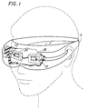
- FIG. 1 is a perspective view of a virtual reality headset incorporating an LCD backlit by the light source of the present invention.
- FIG. 2 is a perspective view of an embodiment of the light source of the present invention.
- FIG. 3 is a cross-sectional view of the light source of FIG. 2 taken along the lines 3-3 of FIG. 2.
- FIG. 4 is an end-on cross-sectional view of the light source of FIG. 2 taken along the lines 4-4 of FIG. 2.
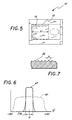
- FIG. 5 is a plan view of the light source of FIG. 2 taken along the lines 5-5 of FIG. 3.
- FIG. 6 is a graph showing the intensity of light emitted from the light source shown in FIGS. 2 as a function of viewing angle.
- FIG. 7 is a fragmentary view in cross section, of a brightness enhancing film as shown in FIG. 3.
- FIG. 8 is a cross sectional view of a second embodiment of the present invention.
- FIG. 9 is a plan view of the embodiment of FIG. 8.
- FIG. 10 is an schematic view of the light source showing the viewing angle.
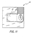
- FIG. 11 is a plan view of an alternate embodiment of the light source which is identical in all respects to the embodiment of FIG. 2 except that the light source is mounted transversely to the configuration depicted in FIG. 2.
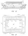
- FIG. 12 is a cross-sectional view of an embodiment utilizing an arrangement of red, blue, and green LEDs which in combination produce white light.
- FIG. 13 is a plan view of the light source of FIG. 12 taken along the lines 13-13 of Fig. 12.
- one preferred embodiment of the present invention comprises a virtual reality headset 5 configured to be worn on the head of a user.
- the headset 5 has a pair of small-area color display panels 26 disposed within an interior cavity 7 of the headset.
- Each of the panels 26 comprises an LCD with a front face and a rear face of identical size.
- Each of the front faces of the panels 26 is positioned behind an eyepiece (not shown) that is directly in front of a respective eye of the user so that each eye views the front face of a single one of the panels.
- each of the faces of the display panels 26 is rectangular, having a length of 1/2" and a width of 1/2"
- the headset is configured to fit against the face of the user sufficiently tightly so that light from ambient sources cannot enter the cavity 7.
- the headset When properly mounted on the user's head, the headset will always be in substantially the same position relative to the user's face, and the display panels 26 will thus also always be in substantially the same position with respect to the user's eyes. Accordingly, each time the headset is worn, the eye of the viewer will have the same viewing position with respect to the display screens 26.
- Each of the panels 26 includes a backlighting apparatus 10, as shown in FIG. 2 and 3.
- the backlight 10 is comprised of a bulb 12, located within a housing 14 having an aperture 18, covered by a diffuser 20, a brightness enhancing film (BEF) 22, and a color filter 24.
- the diffuser 20, BEF 22, and color filter 24 are placed in physical contact with each other, forming a planar structure hereinafter referred to as a light quality enhancing (LQE) apparatus 27.
- the headset 5 has not been shown in FIG. 2 for clarity of illustration, it will be understood that the position 28 would be within the interior cavity 7 of the headset 5.
- the housing 14 has lateral internal dimensions of 13mm x 33mm, and the thickness or depth of the housing is 10mm, slightly larger than the diameter of a standard flashlight bulb.
- the aperture 18 is 13mm square in this embodiment.
- the aperture 18 is preferably smaller than 2 inches square to ensure uniform illumination of the cavity walls 16 opposite the aperture 18 by the incandescent bulb 12.
- the lamp 12 is preferably an incandescent light bulb such as a common flashlight lamp powered by a power source (not shown) connected to wires 19.
- the lamp 12 is preferably entirely enclosed in the housing 14 so that only the wires 19 emerge from the housing 14.
- the wires 19 pass through a small passageway in a wall of the housing 14. The passageway is just large enough to accommodate the wires 19 and is substantially smaller than the diameter of the bulb, thereby minimizing light leakage emanating from the annular space, if present, between the wires and the housing 14.
- the housing 14 which forms a cavity comprising diffusely reflecting interior surfaces 16 preferably having a reflectivity of at least 88%.
- the surfaces 16 may be coated with white paint or more exotic materials such as the Labsphere Corporation's Spectraflect paint. Spectraflect paint's reflectivity is considerably higher than house paint, roughly 98%, while the reflectivity of house paint is approximately 92%.
- the housing 14 may be entirely constructed from a diffusely reflecting material, such as TiO 2 pigmented LexanTM polycarbonate or SpectralonTM plastic, thereby avoiding the need to apply a separate coating to the interior surfaces 16 of the housing 14. The reflectivity of SpectralonTM plastic is about 99%.
- Light emerging from the lamp 12 typically undergoes several reflections within the cavity formed by the housing 14 before eventually emerging from the aperture 18. Because the interior surfaces 16 of the housing 14 are diffusely reflecting, the multitude of diffuse reflections cause the interior surface of the housing 14 opposite the aperture 18 to be uniformly lit and act as a substantially lambertian source, i.e., a light source having the property that the radiance or brightness of the interior cavity surfaces is constant as a function of viewing angle.
- a substantially lambertian source i.e., a light source having the property that the radiance or brightness of the interior cavity surfaces is constant as a function of viewing angle.
- the area of the aperture 18 is the area of the aperture 18.
- this ratio is at least 0.05, and in the preferred embodiment the ratio is close to 0.20.
- the side cavity walls 16 are curved; such an arrangement decreases the combined cavity area, and thus increases the aforementioned ratio of the area of the aperture to the combined cavity area.
- the bottom cavity wall may also be curved as well to decrease the angle ⁇ (shown in FIG. 3) as a function of increasing distance from the bulb.
- the angle 6 is the angle formed between a line drawn from the filament of the bulb 12 and the outward-pointing normal to a plane tangent to the cavity surface at each point.
- the edge-to-edge dimension 31 of the aperture 18, referred to herein as the bisector dimension is the edge-to-edge dimension 31 of the aperture 18, referred to herein as the bisector dimension.
- This bisector dimension extends along a line formed by the juncture of the plane of the aperture and a plane normal to the plane 41 of the aperture 18 extending through the bulb 12 and bisecting the aperture.
- the ratio of the depth of the housing 14 to this bisector dimension affects both the intensity and uniformity of the light visible through the opening of the aperture 18. If this ratio is too large, the aforementioned ratio of the area of the aperture to the combined cavity area becomes too small. With a small ratio, light from bulb 12 will also undergo fewer reflections from the cavity walls 16 and undergo 1/r 2 fall off, resulting in a less-uniform intensity distribution. In the preferred embodiments of the present invention, the ratio is more than approximately 0.10.
- Still another parameter of the present invention is the ratio of the diameter 30 of the envelope of the lamp 12 (typically the width of the bulb) to the depth 32 of the cavity formed by the housing 14. In the preferred embodiment of the present invention, this ratio is sufficiently high to achieve compactness.
- the housing 14 is preferably constructed so that the depth 32 is not substantially greater than the diameter 30 of the bulb. By way of example, the ratio may be 0.60.
- the diffuser 20 is advantageously placed in the opening of the aperture 18 to remove residual nonuniformities such as cosmetic imperfections in the interior surfaces 16 of the cavity.
- the diffuser is comprised of translucent material, typically a readily available thin plastic surface or volume diffuser. Both of these materials are preferred because they are characterized by very low absorption, thus minimizing energy losses.
- the backlight 10 employs the BEF 22 placed between the diffuser 20 and the display 26 to concentrate the illumination, and thereby increases the brightness.
- This angle, ⁇ t (shown at 39 in FIG. 10), is the semi-angle from a normal 36 to the plane of the aperture 18. More specifically, the BEF 22 transmits light rays within ⁇ t . Except for weak side lobes, no light will be transmitted by the BEF beyond the angle ⁇ t .
- a second angle, the viewing angle ⁇ v shown at 41, subtends twice the angle ⁇ t of the BEF 22. Consequently, ⁇ v 2 ⁇ t .
- concentration of the illumination by the BEF 22 (within the angle ⁇ t ), shown in FIG. 10, is symmetrical only in the sense that concentration occurs within a plane coincident with the plane of the paper in FIG. 10.
- the BEF 22 does not provide concentration within the orthogonal plane.
- the BEF of the preferred embodiment is a commercially available thin film having linear pyramidal structures 38.
- the structures 38 transmit only those rays from the cavity that satisfy the incidence angle criteria for transmission into the transmission region bounded by the boundary lines 37. All other rays will be reflected back into the cavity, where they are diffusely reflected again by the cavity walls. In effect, the reflected rays are "recycled" until they are incident on the BEF at an angle which permits them to pass through the BEF into the transmission region.
- the fraction f of light retroreflected by the pyramidal structures 38 of the BEF 22 satisfies the relationship 1-f ⁇ sin ⁇ t .
- the brightness-enhancing effect results from the fact that many of the retroreflected rays are themselves diffusely reflected and eventually are transmitted by the BEF 22. Because the BEF 22 is designed so that ⁇ t ⁇ 90 degrees, it concentrates light within the display range, thereby increasing the intensity of light seen within this range.
- ⁇ t ⁇ 90 degrees
- the use of orthogonally oriented films produces the enhancing effect in two orthogonal planes rather than only along the axis perpendicular to the pyramidal structures, as is the case when only one set of pyramidal structures 38 is used.
- the structure of the film is sufficiently fine that it is imperceptible to the viewer of the display 26 and the light intensity resulting therefrom is as uniform as possible.
- the BEF 22 may be a film having an apex angle a (typically about 100°). Such film is available from 3M.
- an array of two-dimensional micro lenses may be utilized.
- FIG. 6 is a graph of the brightness of light observed as a function of viewing angle ⁇ (here, viewing angle ⁇ is defined as the angle the eye of the observer makes with the plane of the aperture 18).
- FIG. 6 also illustrates an advantageous feature of the present invention, namely the uniformity of the distribution of illumination throughout the viewing range 60. It can be seen that the graph 42 of the light intensity emerging from the BEF 22 as a function of viewing angle ⁇ is highly uniform throughout the entire viewing angle ⁇ .
- the color temperature of the flashlight bulb that comprises the lamp 12 is only about 2800K.
- color LCD displays require a higher color temperature to achieve ideal color purity. Consequently, when an incandescent source is employed as the lamp 12, a filter may be used to shift the color distribution as desired.
- the filter 24 of the preferred embodiment is a blue absorbing filter that shifts the color temperature to between about 4500K and 5500K. Light passing through the filter 24 continues through the LCD 26 to the eye of the viewer located at the position 28.
- the gaps between elements 20, 22, and 24 in FIG. 1 are depicted only for clarity; the thicknesses of and separation between each of the various elements are minimized for the sake of compactness.
- the lamp 12 is situated in the housing 14 so that it is outside of a viewing aperture portion 17.
- viewing aperture portion refers to the portion of the cavity that lies directly beneath the aperture 18. Placement of the lamp 12 outside the viewing aperture portion 17 prevents most of the light rays emanating from the lamp 12 from reaching the aperture 18 without first being reflected off a surface of the cavity. Since only glancing rays from the bulb 12 directly impinge on the LQE 27 and the diffuser 20 scatters these rays, this arrangement allows the intensity distribution of light emerging from the aperture 18 to be relatively uniform.
- FIGs An alternate embodiment of the backlighting system allowing even more compact construction is illustrated in FIGs.
- the lamp 12 is placed in a different portion of the housing 14. In this embodiment, the lamp 12 is placed directly within the viewing aperture portion 17.
- the lamp 12 is shielded from the aperture 18 by an opaque baffle 56.
- the baffle 56 has two diffusely reflecting outer surfaces which are coated with one of the diffusely reflecting materials described above. The diffusely reflecting surfaces of the baffle 56 prevent the lamp 12 from directly illuminating the aperture 18, while reflecting light incident thereon, such as any rays reflected back toward the aperture from the diffuser and the BEF, thus preserving the uniformity of the light distribution. Since the lamp 12 is directly beneath the aperture, as opposed to being set back in the housing 14 outside viewing aperture 17, the housing 14 can be more laterally compact than that of the embodiment of FIG. 2.
- FIG. 8 allows a higher ratio of the aperture surface area to the combined cavity area, thus allowing even greater efficiency in the use of energy emanating from the bulb 12.
- all details of this embodiment such as the coating of the interior surfaces of the housing 14 and the placement of the diffuser, BEF and filter, are identical to those of FIG. 2.
- FIG. 11 A further embodiment, illustrated in FIG. 11, is identical to the embodiment shown in FIGS. 1-5, except for the orientation of the bulb 12. Accordingly, like numbers designate like parts.
- the bulb is oriented so that a line extending along its longitudinal axis is parallel to, but spaced from, the aperture (as opposed to the embodiment shown in FIG. 5, where a line extending along the longitudinal axis of the bulb passes beneath the aperture).
- the bulb in FIG. 11 is rotated 90° relative to the bulb in FIG. 5.
- FIGS. 12 and 13 Yet another embodiment of a lambertian light source is shown in FIGS. 12 and 13.
- red, blue, and green light from light emitting diodes (LED) is mixed together in a manner well known in the art to produce white light.
- a housing 14' comprises a diffusively reflecting cavity having interior cavity walls 16' and an aperture 18' which opens into the cavity.
- the dimensions of the aperture 18' are 16.1mm by 14.1mm for the particular arrangement shown, which uses 2 red LEDs 12'(r), 4 blue LEDs 12'(b), and 18 green LEDs 12'(g).
- FIG. 12 red LEDs 12'(r), 4 blue LEDs 12'(b), and 18 green LEDs 12'(g).
- the LEDs are mounted around the periphery of the aperture 18' within a channel 70 that extends around the entire perimeter of the aperture 18'.
- the channel 70 is formed by a small baffle 72 that extends from the edge of the aperture 18 a short distance into the cavity and along the entire perimeter of the aperture 18'.
- the distance by which the baffle 72 extends into the cavity is no greater than is necessary to prevent the LEDs from being viewed through the aperture 18'.
- the baffle 72 is spaced from the cavity walls 16 by a sufficient distance to permit light from the LED's to diffusively reflect into the portion of the cavity beneath the aperture 18'.
- the depth of the cavity is 5-10 mm.
- the LEDs 12' comprise tiny cubes of solid-state material that emit light.
- the solid-state material is not encased in a housing, and no directional reflectors are used such that the emission is allowed to propagate multidirectionally from plural faces of the solid-state cubes. Such multifaceted emission enhances the uniformity of the intensity of light exiting the aperture 18'.
- the LEDs 12' are positioned so that for each color (red, blue, green) the output from the aperture 18' is substantially uniform with respect to intensity.
- the LEDs 12' are positioned symmetrically, with an equal number of diodes 12' of like color on opposite edges of the rectangular aperture 18'.
- the top edge of the aperture 18' has nine green diodes 12'(g) and one red diode 12'(r), while the bottom edge of the aperture also has nine green diodes 12'(g) and one red diode 12'(r).
- the left edge of the aperture has two blue diodes 12'(b), while the right edge also has two blue diodes 12'(b).
- the diodes preferably have substantial symmetry with respect to sides of the same edge of the aperture 18'.
- the single red diode 12' (r) at the top edge in FIG. 13 is placed substantially in the center of that top edge with five green diodes 12'(g) on the left side and four green diodes 12'(g) on the right side.
- the bottom edge embodies the same symmetry except that the four green diodes are on the left side of the red diode and the five green diodes are on the right side.
- the left aperture edge as seen in FIG.
- each of the two blue diodes 12'(b) is positioned so that it is the same distance from an end of the left aperture edge as it is from the other blue diode.
- the blue diodes 12' (b) at the right aperture edge have this same symmetry with respect to the right aperture edge.
- the combination of LEDs 12' is selected to provide white light.
- a diffuser 20' and BEF 22' are included, as shown in FIG. 12, no color filter is necessary because the combination of red, blue and green colors produces light of sufficient whiteness.
- the present invention thus comprises a highly uniform, efficient, and compact light source for demanding applications such as small color LCD displays in virtual reality systems. However, it also has application in other small-area backlighting systems as well, such as in digital watches or automotive gauges. It is understood that the present disclosure of the preferred embodiment may be changed in the combination and arrangement of parts without departing from the spirit and scope of the invention hereinafter claimed.
Landscapes
- Physics & Mathematics (AREA)
- Nonlinear Science (AREA)
- Optics & Photonics (AREA)
- Mathematical Physics (AREA)
- Chemical & Material Sciences (AREA)
- Crystallography & Structural Chemistry (AREA)
- General Engineering & Computer Science (AREA)
- General Physics & Mathematics (AREA)
- Engineering & Computer Science (AREA)
- Spectroscopy & Molecular Physics (AREA)
- Planar Illumination Modules (AREA)
- Devices For Indicating Variable Information By Combining Individual Elements (AREA)
- Liquid Crystal (AREA)
- Vessels And Coating Films For Discharge Lamps (AREA)
- Illuminated Signs And Luminous Advertising (AREA)
Claims (20)
- Vorrichtung, enthaltend:dadurch gekennzeichnet, daßein Anzeigefeld (26), das eine hintere Oberfläche und eine vordere Oberfläche hat, welches Anzeigefeld (26) mindestens teilweise durchlässig ist, so daß mindestens ein Teil einer Beleuchtung an der hinteren Oberfläche zu der vorderen Oberfläche durchgelassen wird;eine Lichtquelle zur Hintergrundbeleuchtung des Anzeigefeldes (26), welche Lichtquelle enthält:eine Einrichtung (12), die Licht emittiert;ein Gehäuse (14), das eine Öffnung (18) hat, die der hinteren Oberfläche des Anzeigefeldes (26) gegenüberliegt, um die hintere Oberfläche zu beleuchten, sowie einen Diffusor (20) an der Öffnung (18),welches Gehäuse streuende, reflektierende innere Oberflächen hat,die streuenden, reflektierenden Oberflächen einen Hohlraum (7) bilden, welcher Hohlraum (7) eine Tiefe hat, die Licht emittierende Einrichtung (12) in dem Hohlraum (7) angebracht ist, die Öffnung (18) sich in den Hohlraum (7) öffnet, der Hohlraum (7) eine streuende, reflektierende Fläche hat und die Öffnung (18) eine Fläche hat, wobei das Verhältnis der Fläche der Öffnung (18) zu der Summe von (i) der Fläche der Öffnung (18) und (ii) der Fläche des Hohlraumes mindestens 0,05 beträgt, die Öffnung (18) eine Abmessung von Rand zu Rand hat, wobei das Verhältnis der Tiefe (32) zu dieser Abmessung von Rand zu Rand mindestens 0,1 beträgt;der Diffusor (20) so positioniert ist, daß er die Beleuchtung, die von dem Hohlraum (7) durch die Öffnung (18) zu dem Anzeigefeld (26) tritt, streut;ein die Helligkeit verbesserndes Material (22) zwischen dem Diffusor (20) und dem Anzeigefeld (26) angeordnet ist, welches Material (22) die Beleuchtung innerhalb eines Betrachtungswinkels (v). konzentriert, um so die Helligkeit des Anzeigefeldes (26) zu verbessern.
- Vorrichtung nach Anspruch 1, bei welcher die Licht emittierende Einrichtung (12) eine Glühlampe enthält.
- Vorrichtung nach Anspruch 2, bei welcher die Abmessung eine Abmessung in der Mittellinie ist.
- Vorrichtung nach Anspruch 2, bei welcher die Vorrichtung zusätzlich ein Farbfilter (24) enthält, dessen Eigenschaften so gewählt sind, daß es die Weißfärbung des Lichtes von der Glühlampe erhöht, wobei die Farbtemperatur über 4.000°K liegt.
- Vorrichtung nach Anspruch 2, bei welcher die Glühlampe einen Glühfaden hat, der von einer Umhüllung umschlossen ist, wobei das Verhältnis der Tiefe des Gehäuses (14) zu dem Durchmesser der Umhüllung, die den Glühfaden umgibt, kleiner als 1,8 ist.
- Vorrichtung nach Anspruch 2, bei welcher die Glühlampe einen Glühfaden hat, der von einer Umhüllung umschlossen ist, wobei die Tiefe (32), des Gehäuses (14) nicht wesentlich größer als der Durchmesser der Umhüllung ist, die den Glühfaden umgibt.
- Vorrichtung nach Anspruch 1, bei welcher die inneren Oberflächen des Hohlraumes (7) mit weißer Farbe beschichtet sind, die einen Reflexionsgrad hat, der höher ist als 88 Prozent.
- Vorrichtung nach Anspruch 1, bei welcher die reflektierenden inneren Oberflächen des Gehäuses (7) ferner Kunststoff mit hohem Reflexionsgrad enthalten.
- Vorrichtung nach Anspruch 4, bei welcher das Farbfilter (24) zwischen dem Hohlraum (7) und dem Anzeigefeld (26) angeordnet ist.
- Vorrichtung nach Anspruch 1, bei welcher das die Helligkeit verbessernde Material (22) einen Film aus linearen pyramidenförmigen Strukturen enthält.
- Vorrichtung nach Anspruch 10, bei welcher der Betrachtungswinkel (v) nicht mehr als 35 Grad ist.
- Vorrichtung nach Anspruch 10, bei welcher das die Helligkeit verbessernde Material (22) ferner einen zweiten Film aus linearen pyramidenförmigen Strukturen enthält, die in einer orthogonalen Richtung zu dem Film aus linearen pyramidenförmigen Strukturen angeordnet sind.
- Vorrichtung nach Anspruch 2, bei welcher die Glühlampe in dem Hohlraum (7) außerhalb eines Betrachtungsöffnungsabschnitts des Hohlraumes (7) angeordnet ist.
- Vorrichtung nach Anspruch 1, bei welcher das Verhältnis der Tiefe (32) zu der Abmessung mindestens 0,2 beträgt.
- Vorrichtung nach Anspruch 2, bei weicher die Glühlampe innerhalb eines Betrachtungsöffnungsabschnitts des Hohlraumes (7) angeordnet ist, wobei das Gehäuse (14) ferner eine Abschirmung enthält, die zwischen der Glühlampe und der Öffnung angeordnet ist.
- Vorrichtung nach Anspruch 1, bei welcher die Öffnung rechteckig ist und bei welcher keine der Seiten der Öffnung eine Länge von 2 Zoll überschreitet.
- Verfahren zur Hintergrundbeleuchtung eines Anzeigefeldes (26), enthaltend:Erzeugen von Beleuchtung aus einer im wesentlichen Lambertschen Lichtquelle, die einen Hohlraum (7) mit diffus reflektierenden Innenwänden und einer Öffnung (18) enthält, wobei der Schritt des Erzeugens der Beleuchtung den Schritt des Richtens von Lichtstrahlen von dem äußeren Umfang der Öffnung (18) in den Hohlraum (7) in der Weise, daß das aus der Öffnung (18) austretende Licht eine im wesentlichen gleichmäßige Intensität und Farbe hat, umfaßt;Verwenden eines Diffusors (20), um Licht von der im wesentlichen Lambertschen Lichtquelle zu streuen;Verwenden eines die Helligkeit verbessernden Filmes (22), um das gestreute Licht in einen vorbestimmten winkelbereich zu konzentrieren, ohne die Gleichförmigkeit des gestreuten Lichtes wesentlich zu verringern; undRichten des konzentrierten, gestreuten Lichtes auf das Anzeigefeld (26).
- Verfahren nach Anspruch 17, ferner enthaltend den Schritt des Verwendens eines Farbfilters (24), um die Farbtemperatur des konzentrierten, gestreuten Lichtes auf einen Wert über annähernd 4.000°K zu erhöhen.
- Vorrichtung nach Anspruch 1, bei welcher die Lichtquelle Licht von einem einzelnen Ort innerhalb des Hohlraumes emittiert.
- Vorrichtung nach Anspruch 1, bei welcher die Lichtquelle so positioniert ist, daß die Beleuchtungsquelle durch die Öffnung nicht direkt sichtbar ist.
Applications Claiming Priority (5)
| Application Number | Priority Date | Filing Date | Title |
|---|---|---|---|
| US08/131,659 US5440197A (en) | 1993-10-05 | 1993-10-05 | Backlighting apparatus for uniformly illuminating a display panel |
| US131659 | 1993-10-05 | ||
| US08/317,209 US5684354A (en) | 1993-10-05 | 1994-10-03 | Backlighting apparatus for uniformly illuminating a display panel |
| US317209 | 1994-10-03 | ||
| PCT/US1994/011264 WO1995010066A1 (en) | 1993-10-05 | 1994-10-04 | Light source for backlighting |
Publications (3)
| Publication Number | Publication Date |
|---|---|
| EP0722576A1 EP0722576A1 (de) | 1996-07-24 |
| EP0722576A4 EP0722576A4 (de) | 1998-05-06 |
| EP0722576B1 true EP0722576B1 (de) | 2001-08-01 |
Family
ID=26829698
Family Applications (1)
| Application Number | Title | Priority Date | Filing Date |
|---|---|---|---|
| EP94931796A Expired - Lifetime EP0722576B1 (de) | 1993-10-05 | 1994-10-04 | Lichtquelle für hintergrundsbeleuchtung |
Country Status (6)
| Country | Link |
|---|---|
| US (1) | US5892325A (de) |
| EP (1) | EP0722576B1 (de) |
| CN (1) | CN1051379C (de) |
| AT (1) | ATE203836T1 (de) |
| CA (1) | CA2173336C (de) |
| DE (1) | DE69427864T2 (de) |
Families Citing this family (57)
| Publication number | Priority date | Publication date | Assignee | Title |
|---|---|---|---|---|
| US6486862B1 (en) | 1996-10-31 | 2002-11-26 | Kopin Corporation | Card reader display system |
| US6545654B2 (en) | 1996-10-31 | 2003-04-08 | Kopin Corporation | Microdisplay for portable communication systems |
| US6909419B2 (en) * | 1997-10-31 | 2005-06-21 | Kopin Corporation | Portable microdisplay system |
| US6552704B2 (en) | 1997-10-31 | 2003-04-22 | Kopin Corporation | Color display with thin gap liquid crystal |
| US6490104B1 (en) | 2000-09-15 | 2002-12-03 | Three-Five Systems, Inc. | Illumination system for a micro display |
| US6563648B2 (en) | 2000-10-20 | 2003-05-13 | Three-Five Systems, Inc. | Compact wide field of view imaging system |
| US6542307B2 (en) | 2000-10-20 | 2003-04-01 | Three-Five Systems, Inc. | Compact near-eye illumination system |
| WO2002048989A2 (en) * | 2000-12-15 | 2002-06-20 | Kopin Corporation | Display housing |
| US7253852B2 (en) | 2001-04-25 | 2007-08-07 | Kopin Corporation | Polarizer removal in a microdisplay system |
| JP4348409B2 (ja) * | 2001-02-27 | 2009-10-21 | ドルビー ラボラトリーズ ライセンシング コーポレイション | 高ダイナミック・レンジ表示装置 |
| US8684584B2 (en) * | 2001-05-16 | 2014-04-01 | Benzion Inditsky | Ultra-thin backlight |
| US7064740B2 (en) * | 2001-11-09 | 2006-06-20 | Sharp Laboratories Of America, Inc. | Backlit display with improved dynamic range |
| US8687271B2 (en) | 2002-03-13 | 2014-04-01 | Dolby Laboratories Licensing Corporation | N-modulation displays and related methods |
| EP2378507B1 (de) * | 2002-03-13 | 2018-05-09 | Dolby Laboratories Licensing Corporation | Kompensation des ausfalles eines lichtemittierenden elementes in einer anzeige |
| US7021801B2 (en) * | 2002-09-19 | 2006-04-04 | Everbrite, Llc | High-intensity directional light |
| CN100442121C (zh) * | 2003-06-27 | 2008-12-10 | 奇美电子股份有限公司 | 照明装置 |
| US7623105B2 (en) | 2003-11-21 | 2009-11-24 | Sharp Laboratories Of America, Inc. | Liquid crystal display with adaptive color |
| US7164284B2 (en) * | 2003-12-18 | 2007-01-16 | Sharp Laboratories Of America, Inc. | Dynamic gamma for a liquid crystal display |
| US20050248553A1 (en) * | 2004-05-04 | 2005-11-10 | Sharp Laboratories Of America, Inc. | Adaptive flicker and motion blur control |
| US7602369B2 (en) | 2004-05-04 | 2009-10-13 | Sharp Laboratories Of America, Inc. | Liquid crystal display with colored backlight |
| US7612757B2 (en) * | 2004-05-04 | 2009-11-03 | Sharp Laboratories Of America, Inc. | Liquid crystal display with modulated black point |
| US8395577B2 (en) * | 2004-05-04 | 2013-03-12 | Sharp Laboratories Of America, Inc. | Liquid crystal display with illumination control |
| US7872631B2 (en) * | 2004-05-04 | 2011-01-18 | Sharp Laboratories Of America, Inc. | Liquid crystal display with temporal black point |
| US7505018B2 (en) * | 2004-05-04 | 2009-03-17 | Sharp Laboratories Of America, Inc. | Liquid crystal display with reduced black level insertion |
| US7777714B2 (en) * | 2004-05-04 | 2010-08-17 | Sharp Laboratories Of America, Inc. | Liquid crystal display with adaptive width |
| US7532192B2 (en) * | 2004-05-04 | 2009-05-12 | Sharp Laboratories Of America, Inc. | Liquid crystal display with filtered black point |
| US7023451B2 (en) * | 2004-06-14 | 2006-04-04 | Sharp Laboratories Of America, Inc. | System for reducing crosstalk |
| US7556836B2 (en) * | 2004-09-03 | 2009-07-07 | Solae, Llc | High protein snack product |
| US7898519B2 (en) * | 2005-02-17 | 2011-03-01 | Sharp Laboratories Of America, Inc. | Method for overdriving a backlit display |
| US8050511B2 (en) * | 2004-11-16 | 2011-11-01 | Sharp Laboratories Of America, Inc. | High dynamic range images from low dynamic range images |
| US8050512B2 (en) | 2004-11-16 | 2011-11-01 | Sharp Laboratories Of America, Inc. | High dynamic range images from low dynamic range images |
| US7525528B2 (en) * | 2004-11-16 | 2009-04-28 | Sharp Laboratories Of America, Inc. | Technique that preserves specular highlights |
| KR100647317B1 (ko) | 2005-02-03 | 2006-11-23 | 삼성전자주식회사 | 다채널 형광 측정용 광학계 및 이를 채용한 다채널 형광시료 분석 장치 |
| EP1696260B1 (de) * | 2005-02-08 | 2013-09-25 | BMG Gesellschaft für moderne Informationssysteme mbH | Flüssigkristallanzeigeeinrichtung sowie Flüssigkristallanzeigeanordnung mit einer Mehrzahl von solchen Flüssigkristallanzeigeeinrichtungen |
| CN101171452B (zh) * | 2005-03-12 | 2010-12-08 | 3M创新有限公司 | 照明设备及其制造方法 |
| CN100464233C (zh) * | 2006-01-17 | 2009-02-25 | 群康科技(深圳)有限公司 | 背光模块 |
| US9143657B2 (en) * | 2006-01-24 | 2015-09-22 | Sharp Laboratories Of America, Inc. | Color enhancement technique using skin color detection |
| US8121401B2 (en) * | 2006-01-24 | 2012-02-21 | Sharp Labortories of America, Inc. | Method for reducing enhancement of artifacts and noise in image color enhancement |
| CN101627251A (zh) | 2006-05-02 | 2010-01-13 | 舒伯布尔斯公司 | 用于led灯泡的散热设计 |
| EP2022077A4 (de) | 2006-05-02 | 2011-10-26 | Superbulbs Inc | Kunststoff-led-birne |
| CA2645228A1 (en) | 2006-05-02 | 2007-11-15 | Superbulbs, Inc. | Method of light dispersion and preferential scattering of certain wavelengths of light for light-emitting diodes and bulbs constructed therefrom |
| CN100437153C (zh) * | 2006-05-25 | 2008-11-26 | 友达光电股份有限公司 | 背光模块及其使用的光漫射模块 |
| US8941580B2 (en) * | 2006-11-30 | 2015-01-27 | Sharp Laboratories Of America, Inc. | Liquid crystal display with area adaptive backlight |
| WO2008092276A1 (en) * | 2007-02-01 | 2008-08-07 | Dolby Laboratories Licensing Corporation | Calibration of displays having spatially-variable backlight |
| US7874704B2 (en) * | 2007-05-21 | 2011-01-25 | Waqidi Falicoff | LED luminance-augmentation via specular retroreflection, including collimators that escape the étendue limit |
| US7672549B2 (en) * | 2007-09-10 | 2010-03-02 | Banyan Energy, Inc. | Solar energy concentrator |
| US8412010B2 (en) | 2007-09-10 | 2013-04-02 | Banyan Energy, Inc. | Compact optics for concentration and illumination systems |
| US7664350B2 (en) * | 2007-09-10 | 2010-02-16 | Banyan Energy, Inc. | Compact optics for concentration, aggregation and illumination of light energy |
| WO2009045438A1 (en) | 2007-10-03 | 2009-04-09 | Superbulbs, Inc. | Glass led light bulbs |
| US8415695B2 (en) | 2007-10-24 | 2013-04-09 | Switch Bulb Company, Inc. | Diffuser for LED light sources |
| US20090322800A1 (en) | 2008-06-25 | 2009-12-31 | Dolby Laboratories Licensing Corporation | Method and apparatus in various embodiments for hdr implementation in display devices |
| US20100214282A1 (en) * | 2009-02-24 | 2010-08-26 | Dolby Laboratories Licensing Corporation | Apparatus for providing light source modulation in dual modulator displays |
| KR20130130707A (ko) | 2010-10-28 | 2013-12-02 | 반얀 에너지, 인크 | 집광 및 조명 시스템을 위한 방향전환 광소자 |
| US9013793B2 (en) * | 2011-09-21 | 2015-04-21 | Google Inc. | Lightweight eyepiece for head mounted display |
| US8591069B2 (en) | 2011-09-21 | 2013-11-26 | Switch Bulb Company, Inc. | LED light bulb with controlled color distribution using quantum dots |
| CN104765152B (zh) | 2015-05-06 | 2017-10-24 | 京东方科技集团股份有限公司 | 一种虚拟现实眼镜 |
| CN105652490B (zh) * | 2016-03-25 | 2020-03-24 | 京东方科技集团股份有限公司 | 一种显示眼镜及其驱动方法 |
Family Cites Families (51)
| Publication number | Priority date | Publication date | Assignee | Title |
|---|---|---|---|---|
| US1734834A (en) * | 1927-06-28 | 1929-11-05 | Willard M Steward | Light projector |
| US2761056A (en) * | 1953-02-13 | 1956-08-28 | Lazo John | Instrument illuminating means |
| US2907869A (en) * | 1957-08-14 | 1959-10-06 | Edwin M Hudson | Instrument illuminator |
| US3223833A (en) * | 1964-12-15 | 1965-12-14 | Gen Time Corp | Illuminated dial |
| US3349234A (en) * | 1965-06-01 | 1967-10-24 | Honeywell Inc | Illuminating apparatus |
| US3586851A (en) * | 1969-02-24 | 1971-06-22 | Robert R Rudolph | Cool light |
| JPS50123295A (de) * | 1974-03-15 | 1975-09-27 | ||
| US3957351A (en) * | 1974-09-16 | 1976-05-18 | Rockwell International Corporation | Backlighted display apparatus |
| US4043636A (en) * | 1974-12-23 | 1977-08-23 | Intel Corporation | Illumination-panel for liquid crystal display of similar device |
| CH609193B5 (fr) * | 1976-02-25 | 1979-08-31 | Ebauches Sa | Cellule d'affichage électro-optique passif et procédé pour sa fabrication |
| US4183628A (en) * | 1976-05-20 | 1980-01-15 | Ebauches S.A. | Electronic watch and display device for such watch |
| US4195915A (en) * | 1978-05-05 | 1980-04-01 | Hughes Aircraft Company | Liquid crystal image projector system |
| US4212048A (en) * | 1978-06-16 | 1980-07-08 | General Electric Company | Illuminator for reflective dichroic liquid crystal displays |
| US4252416A (en) * | 1978-10-23 | 1981-02-24 | Societe Suisse Pour L'industrie Horlogere Management Services S.A. | Optical instrument for gathering and distribution of light |
| USRE33987E (en) * | 1980-03-24 | 1992-07-07 | Seiko Epson Corporation | Backlighted liquid crystal display |
| US4453200A (en) * | 1981-07-20 | 1984-06-05 | Rockwell International Corporation | Apparatus for lighting a passive display |
| US4440474A (en) * | 1981-12-21 | 1984-04-03 | Rockwell International Corporation | Illuminated passive display from an oblique angle |
| US4528617A (en) * | 1982-02-08 | 1985-07-09 | Sheltered Workshop For The Disabled, Inc. | Light distribution apparatus |
| JPS59119436U (ja) * | 1983-01-29 | 1984-08-11 | 旭光学工業株式会社 | カメラのフアインダ内情報表示装置 |
| US4616295A (en) * | 1984-07-03 | 1986-10-07 | Hewlett-Packard Company | Apparatus for mounting and illuminating liquid crystal displays |
| JPS6134583A (ja) * | 1984-07-26 | 1986-02-18 | シャープ株式会社 | 照明装置 |
| CA1243867A (en) * | 1984-10-12 | 1988-11-01 | National Research Council Of Canada | Viewing angle colour sensitive lighting accessory |
| DE3605000A1 (de) * | 1985-02-22 | 1986-09-04 | Sharp Kk | Beleuchtungsvorrichtung |
| FR2582839B1 (fr) * | 1985-06-04 | 1987-07-24 | Veglia | Dispositif d'affichage a cristaux liquides |
| JPS6217904A (ja) * | 1985-07-15 | 1987-01-26 | 双葉電子工業株式会社 | 光源 |
| JP2823156B2 (ja) * | 1985-07-23 | 1998-11-11 | キヤノン株式会社 | ディスプレイ装置 |
| US4720706A (en) * | 1985-08-26 | 1988-01-19 | Stine Edward V | Method and apparatus for electro-optical color imaging |
| US5008658A (en) * | 1986-12-09 | 1991-04-16 | Zenith Electronics Corporation | Domed light housing for back-lit LCD display |
| US4735495A (en) * | 1986-12-12 | 1988-04-05 | General Electric Co. | Light source for liquid crystal display panels utilizing internally reflecting light pipes and integrating sphere |
| DE3806421A1 (de) * | 1987-03-04 | 1988-11-24 | Citizen Watch Co Ltd | Beleuchtungsvorrichtung fuer ein fluessigkristallanzeigegeraet |
| JP2557071B2 (ja) * | 1987-09-28 | 1996-11-27 | 三菱電機株式会社 | 液晶表示装置 |
| US4798448A (en) * | 1988-02-16 | 1989-01-17 | General Electric Company | High efficiency illumination system for display devices |
| NL8800951A (nl) * | 1988-04-13 | 1989-11-01 | Philips Nv | Weergeefinrichting. |
| JPH0679120B2 (ja) * | 1988-08-06 | 1994-10-05 | 三菱電機株式会社 | 面発光装置 |
| JPH0262585A (ja) * | 1988-08-29 | 1990-03-02 | Sharp Corp | 透過型液晶表示装置 |
| DE3919925A1 (de) * | 1989-06-19 | 1990-12-20 | Inotec Gmbh Ges Fuer Innovativ | Beleuchtete, anzeigeeinheit, insbesondere hausnummer, verkehrsschild, werbetraeger |
| JPH0365982A (ja) * | 1989-08-03 | 1991-03-20 | Pioneer Electron Corp | 表示装置における表示板照明装置 |
| US5128783A (en) * | 1990-01-31 | 1992-07-07 | Ois Optical Imaging Systems, Inc. | Diffusing/collimating lens array for a liquid crystal display |
| US5093765A (en) * | 1990-02-16 | 1992-03-03 | Tosoh Corporation | Back lighting device for a panel |
| US5161041A (en) * | 1990-04-26 | 1992-11-03 | Ois Optical Imaging Systems, Inc. | Lighting assembly for a backlit electronic display including an integral image splitting and collimating means |
| US5202950A (en) * | 1990-09-27 | 1993-04-13 | Compaq Computer Corporation | Backlighting system with faceted light pipes |
| US5050946A (en) * | 1990-09-27 | 1991-09-24 | Compaq Computer Corporation | Faceted light pipe |
| US5188453A (en) * | 1991-01-28 | 1993-02-23 | Holophane Company, Inc. | Internally illuminated sign |
| US5169230A (en) * | 1991-06-20 | 1992-12-08 | The United States Of America As Represented By The Secretary Of The Air Force | Lamp for producing light intensity uniformity |
| EP0531939B1 (de) * | 1991-09-09 | 1999-12-29 | Enplas Corporation | Oberflächenbeleuchtung |
| US5655832A (en) * | 1992-04-16 | 1997-08-12 | Tir Technologies, Inc. | Multiple wavelength light processor |
| US5440197A (en) * | 1993-10-05 | 1995-08-08 | Tir Technologies, Inc. | Backlighting apparatus for uniformly illuminating a display panel |
| GB2283849B (en) * | 1993-10-29 | 1997-07-02 | Protec Fire Detection Plc | Luminaire |
| US5485291A (en) * | 1994-02-22 | 1996-01-16 | Precision Lamp, Inc. | Uniformly thin, high efficiency large area lighting panel with two facet grooves that are spaced apart and have light source facing facets with smaller slopes than the facets facing away from the light source |
| US5575549A (en) * | 1994-08-12 | 1996-11-19 | Enplas Corporation | Surface light source device |
| US5650865A (en) * | 1995-03-21 | 1997-07-22 | Hughes Electronics | Holographic backlight for flat panel displays |
-
1994
- 1994-10-04 AT AT94931796T patent/ATE203836T1/de not_active IP Right Cessation
- 1994-10-04 CA CA002173336A patent/CA2173336C/en not_active Expired - Fee Related
- 1994-10-04 DE DE69427864T patent/DE69427864T2/de not_active Expired - Lifetime
- 1994-10-04 EP EP94931796A patent/EP0722576B1/de not_active Expired - Lifetime
- 1994-10-04 CN CN94193692A patent/CN1051379C/zh not_active Expired - Lifetime
-
1997
- 1997-10-27 US US08/958,222 patent/US5892325A/en not_active Expired - Lifetime
Also Published As
| Publication number | Publication date |
|---|---|
| EP0722576A4 (de) | 1998-05-06 |
| US5892325A (en) | 1999-04-06 |
| ATE203836T1 (de) | 2001-08-15 |
| CA2173336C (en) | 2005-08-16 |
| EP0722576A1 (de) | 1996-07-24 |
| DE69427864T2 (de) | 2002-07-04 |
| DE69427864D1 (de) | 2001-09-06 |
| CN1051379C (zh) | 2000-04-12 |
| CA2173336A1 (en) | 1995-04-13 |
| CN1132558A (zh) | 1996-10-02 |
Similar Documents
| Publication | Publication Date | Title |
|---|---|---|
| US5892325A (en) | Backlighting apparatus for uniformly illuminating a display panel | |
| US6043591A (en) | Light source utilizing diffusive reflective cavity | |
| US6313892B2 (en) | Light source utilizing reflective cavity having sloped side surfaces | |
| US6007209A (en) | Light source for backlighting | |
| CN114730044B (zh) | 定向照明设备和隐私显示器 | |
| US11231568B2 (en) | Illumination apparatus | |
| JP5290279B2 (ja) | 照明システム、照明器具及びバックライティングユニット | |
| JP4838986B2 (ja) | 輝度プロフィールの生成装置 | |
| KR101266788B1 (ko) | 고휘도 백라이트를 구비한 디스플레이 | |
| US6951401B2 (en) | Compact illumination system and display device | |
| JP5475684B2 (ja) | 照明システム、照明器具及びバックライトユニット | |
| US7172328B2 (en) | Compact lighting system and display device | |
| EP2067065B1 (de) | Beleuchtungssystem, leuchte und anzeigevorrichtung | |
| EP1865251A1 (de) | Lichtleitelement, dieses einsetzende planare beleuchtungsvorrichtung und stabartige beleuchtungsvorrichtung | |
| EP1693700A1 (de) | Leuchtdiodeneinheit für eine Rückbeleuchtungsvorrichtung | |
| US20070153543A1 (en) | Flat panel displays with primary viewing envelopes away from displyay panel normal | |
| US20040105247A1 (en) | Diffusing backlight assembly | |
| US20070047219A1 (en) | Direct-lit backlight having light sources with bifunctional diverters | |
| US20080266895A1 (en) | Optical plate and backlight module using the same | |
| AU2002240732A1 (en) | Illuminated background display apparatus |
Legal Events
| Date | Code | Title | Description |
|---|---|---|---|
| PUAI | Public reference made under article 153(3) epc to a published international application that has entered the european phase |
Free format text: ORIGINAL CODE: 0009012 |
|
| 17P | Request for examination filed |
Effective date: 19960403 |
|
| AK | Designated contracting states |
Kind code of ref document: A1 Designated state(s): AT BE CH DE DK ES FR GB GR IE IT LI LU MC NL PT SE |
|
| A4 | Supplementary search report drawn up and despatched |
Effective date: 19980316 |
|
| AK | Designated contracting states |
Kind code of ref document: A4 Designated state(s): AT BE CH DE DK ES FR GB GR IE IT LI LU MC NL PT SE |
|
| GRAG | Despatch of communication of intention to grant |
Free format text: ORIGINAL CODE: EPIDOS AGRA |
|
| GRAG | Despatch of communication of intention to grant |
Free format text: ORIGINAL CODE: EPIDOS AGRA |
|
| 17Q | First examination report despatched |
Effective date: 20000523 |
|
| GRAG | Despatch of communication of intention to grant |
Free format text: ORIGINAL CODE: EPIDOS AGRA |
|
| GRAG | Despatch of communication of intention to grant |
Free format text: ORIGINAL CODE: EPIDOS AGRA |
|
| GRAH | Despatch of communication of intention to grant a patent |
Free format text: ORIGINAL CODE: EPIDOS IGRA |
|
| GRAH | Despatch of communication of intention to grant a patent |
Free format text: ORIGINAL CODE: EPIDOS IGRA |
|
| GRAH | Despatch of communication of intention to grant a patent |
Free format text: ORIGINAL CODE: EPIDOS IGRA |
|
| GRAH | Despatch of communication of intention to grant a patent |
Free format text: ORIGINAL CODE: EPIDOS IGRA |
|
| GRAG | Despatch of communication of intention to grant |
Free format text: ORIGINAL CODE: EPIDOS AGRA |
|
| GRAA | (expected) grant |
Free format text: ORIGINAL CODE: 0009210 |
|
| AK | Designated contracting states |
Kind code of ref document: B1 Designated state(s): AT BE CH DE DK ES FR GB GR IE IT LI LU MC NL PT SE |
|
| PG25 | Lapsed in a contracting state [announced via postgrant information from national office to epo] |
Ref country code: NL Free format text: LAPSE BECAUSE OF FAILURE TO SUBMIT A TRANSLATION OF THE DESCRIPTION OR TO PAY THE FEE WITHIN THE PRESCRIBED TIME-LIMIT Effective date: 20010801 Ref country code: LI Free format text: LAPSE BECAUSE OF FAILURE TO SUBMIT A TRANSLATION OF THE DESCRIPTION OR TO PAY THE FEE WITHIN THE PRESCRIBED TIME-LIMIT Effective date: 20010801 Ref country code: IT Free format text: LAPSE BECAUSE OF FAILURE TO SUBMIT A TRANSLATION OF THE DESCRIPTION OR TO PAY THE FEE WITHIN THE PRE;WARNING: LAPSES OF ITALIAN PATENTS WITH EFFECTIVE DATE BEFORE 2007 MAY HAVE OCCURRED AT ANY TIME BEFORE 2007. THE CORRECT EFFECTIVE DATE MAY BE DIFFERENT FROM THE ONE RECORDED.SCRIBED TIME-LIMIT Effective date: 20010801 Ref country code: GR Free format text: LAPSE BECAUSE OF NON-PAYMENT OF DUE FEES Effective date: 20010801 Ref country code: CH Free format text: LAPSE BECAUSE OF FAILURE TO SUBMIT A TRANSLATION OF THE DESCRIPTION OR TO PAY THE FEE WITHIN THE PRESCRIBED TIME-LIMIT Effective date: 20010801 Ref country code: BE Free format text: LAPSE BECAUSE OF FAILURE TO SUBMIT A TRANSLATION OF THE DESCRIPTION OR TO PAY THE FEE WITHIN THE PRESCRIBED TIME-LIMIT Effective date: 20010801 Ref country code: AT Free format text: LAPSE BECAUSE OF FAILURE TO SUBMIT A TRANSLATION OF THE DESCRIPTION OR TO PAY THE FEE WITHIN THE PRESCRIBED TIME-LIMIT Effective date: 20010801 |
|
| REF | Corresponds to: |
Ref document number: 203836 Country of ref document: AT Date of ref document: 20010815 Kind code of ref document: T |
|
| REG | Reference to a national code |
Ref country code: CH Ref legal event code: EP |
|
| REG | Reference to a national code |
Ref country code: IE Ref legal event code: FG4D |
|
| REF | Corresponds to: |
Ref document number: 69427864 Country of ref document: DE Date of ref document: 20010906 |
|
| PG25 | Lapsed in a contracting state [announced via postgrant information from national office to epo] |
Ref country code: MC Free format text: LAPSE BECAUSE OF NON-PAYMENT OF DUE FEES Effective date: 20011004 Ref country code: LU Free format text: LAPSE BECAUSE OF NON-PAYMENT OF DUE FEES Effective date: 20011004 Ref country code: IE Free format text: LAPSE BECAUSE OF FAILURE TO SUBMIT A TRANSLATION OF THE DESCRIPTION OR TO PAY THE FEE WITHIN THE PRESCRIBED TIME-LIMIT Effective date: 20011004 |
|
| PG25 | Lapsed in a contracting state [announced via postgrant information from national office to epo] |
Ref country code: SE Free format text: LAPSE BECAUSE OF FAILURE TO SUBMIT A TRANSLATION OF THE DESCRIPTION OR TO PAY THE FEE WITHIN THE PRESCRIBED TIME-LIMIT Effective date: 20011101 Ref country code: DK Free format text: LAPSE BECAUSE OF FAILURE TO SUBMIT A TRANSLATION OF THE DESCRIPTION OR TO PAY THE FEE WITHIN THE PRESCRIBED TIME-LIMIT Effective date: 20011101 |
|
| PG25 | Lapsed in a contracting state [announced via postgrant information from national office to epo] |
Ref country code: PT Free format text: LAPSE BECAUSE OF FAILURE TO SUBMIT A TRANSLATION OF THE DESCRIPTION OR TO PAY THE FEE WITHIN THE PRESCRIBED TIME-LIMIT Effective date: 20011105 |
|
| ET | Fr: translation filed | ||
| REG | Reference to a national code |
Ref country code: GB Ref legal event code: IF02 |
|
| NLV1 | Nl: lapsed or annulled due to failure to fulfill the requirements of art. 29p and 29m of the patents act | ||
| REG | Reference to a national code |
Ref country code: CH Ref legal event code: PL |
|
| PG25 | Lapsed in a contracting state [announced via postgrant information from national office to epo] |
Ref country code: ES Free format text: LAPSE BECAUSE OF FAILURE TO SUBMIT A TRANSLATION OF THE DESCRIPTION OR TO PAY THE FEE WITHIN THE PRESCRIBED TIME-LIMIT Effective date: 20020228 |
|
| PLBE | No opposition filed within time limit |
Free format text: ORIGINAL CODE: 0009261 |
|
| STAA | Information on the status of an ep patent application or granted ep patent |
Free format text: STATUS: NO OPPOSITION FILED WITHIN TIME LIMIT |
|
| 26N | No opposition filed | ||
| REG | Reference to a national code |
Ref country code: IE Ref legal event code: MM4A |
|
| REG | Reference to a national code |
Ref country code: FR Ref legal event code: CD |
|
| REG | Reference to a national code |
Ref country code: GB Ref legal event code: 732E |
|
| REG | Reference to a national code |
Ref country code: FR Ref legal event code: TP |
|
| PGFP | Annual fee paid to national office [announced via postgrant information from national office to epo] |
Ref country code: DE Payment date: 20101027 Year of fee payment: 17 |
|
| PGFP | Annual fee paid to national office [announced via postgrant information from national office to epo] |
Ref country code: GB Payment date: 20101025 Year of fee payment: 17 |
|
| PGFP | Annual fee paid to national office [announced via postgrant information from national office to epo] |
Ref country code: FR Payment date: 20111028 Year of fee payment: 18 |
|
| REG | Reference to a national code |
Ref country code: DE Ref legal event code: R082 Ref document number: 69427864 Country of ref document: DE |
|
| GBPC | Gb: european patent ceased through non-payment of renewal fee |
Effective date: 20121004 |
|
| REG | Reference to a national code |
Ref country code: FR Ref legal event code: ST Effective date: 20130628 |
|
| PG25 | Lapsed in a contracting state [announced via postgrant information from national office to epo] |
Ref country code: DE Free format text: LAPSE BECAUSE OF NON-PAYMENT OF DUE FEES Effective date: 20130501 Ref country code: GB Free format text: LAPSE BECAUSE OF NON-PAYMENT OF DUE FEES Effective date: 20121004 |
|
| REG | Reference to a national code |
Ref country code: DE Ref legal event code: R119 Ref document number: 69427864 Country of ref document: DE Effective date: 20130501 |
|
| PG25 | Lapsed in a contracting state [announced via postgrant information from national office to epo] |
Ref country code: FR Free format text: LAPSE BECAUSE OF NON-PAYMENT OF DUE FEES Effective date: 20121031 |