EP0722745A1 - Dispositif d'alimentation d'un fluide - Google Patents
Dispositif d'alimentation d'un fluide Download PDFInfo
- Publication number
- EP0722745A1 EP0722745A1 EP96300441A EP96300441A EP0722745A1 EP 0722745 A1 EP0722745 A1 EP 0722745A1 EP 96300441 A EP96300441 A EP 96300441A EP 96300441 A EP96300441 A EP 96300441A EP 0722745 A1 EP0722745 A1 EP 0722745A1
- Authority
- EP
- European Patent Office
- Prior art keywords
- fluid
- elastic film
- rubber state
- state elastic
- tube
- Prior art date
- Legal status (The legal status is an assumption and is not a legal conclusion. Google has not performed a legal analysis and makes no representation as to the accuracy of the status listed.)
- Granted
Links
Images

Classifications
-
- A—HUMAN NECESSITIES
- A61—MEDICAL OR VETERINARY SCIENCE; HYGIENE
- A61M—DEVICES FOR INTRODUCING MEDIA INTO, OR ONTO, THE BODY; DEVICES FOR TRANSDUCING BODY MEDIA OR FOR TAKING MEDIA FROM THE BODY; DEVICES FOR PRODUCING OR ENDING SLEEP OR STUPOR
- A61M5/00—Devices for bringing media into the body in a subcutaneous, intra-vascular or intramuscular way; Accessories therefor, e.g. filling or cleaning devices, arm-rests
- A61M5/14—Infusion devices, e.g. infusing by gravity; Blood infusion; Accessories therefor
- A61M5/142—Pressure infusion, e.g. using pumps
- A61M5/145—Pressure infusion, e.g. using pumps using pressurised reservoirs, e.g. pressurised by means of pistons
- A61M5/148—Pressure infusion, e.g. using pumps using pressurised reservoirs, e.g. pressurised by means of pistons flexible, e.g. independent bags
- A61M5/152—Pressure infusion, e.g. using pumps using pressurised reservoirs, e.g. pressurised by means of pistons flexible, e.g. independent bags pressurised by contraction of elastic reservoirs
Definitions
- the present invention relates to an apparatus for supplying fluid which continuously supplies fluid contained within a rubber state elastic film of a tube form by the contracting power of the rubber state elastic film.
- the present invention relates to an apparatus for supplying fluid used for continuously supplying a living body such as , a human body, an animal, and so on with medical fluid, a transfusion and so on, or for continuously supplying plants with water, nutrients (fluid), medical fluid (an insecticide fluid) and so on, and further, for continuously supplying a fish aquarium with medical fluid such as an antibiotic, or the like, bait (fluid), or nutrients (fluid) for water plants.
- the above-described apparatus is provided with and has a protection case of a cylindrical form, a balloon consisting of an elastic material, sealed within this protection case and containing medical fluid therein, the inflow portion provided on the surface side of one end of the above-described protection case introducing the medical fluid into the balloon, an outflow prevention means such as , for example, a partition wall provided at this inflow portion consisting of soft rubber capable of being sealed, the outflow portion provided on the surface side of the other end of the above-described protection case, through which medical fluid flows out from within the above-described balloon, an introduction tube connected to this outflow portion, and an injector needle connected to the forward end of this introduction tube.
- a protection case of a cylindrical form a balloon consisting of an elastic material, sealed within this protection case and containing medical fluid therein, the inflow portion provided on the surface side of one end of the above-described protection case introducing the medical fluid into the balloon, an outflow prevention means such as , for example, a partition wall provided at this inflow portion consisting
- a syringe injector
- the medical fluid is introduced into the balloon expanding the balloon.
- the medical fluid contained within the balloon is prevented from flowing out of the inflow portion by the outflow prevention means, and is continuously injected into a human body in a small amount through the introduction tube by the contracting power of the balloon.
- the above-described arrangement wherein the medical fluid inflow portion and the medical fluid outflow portion are provided at the surface sides of both ends (opposite sides) of the protection case, has the disadvantages of being difficult to hold, and inconvenient to carry, since the medical fluid inflow portion and the medical fluid outflow portion protrude from both sides of the protection case, for example, when a patient having the medical fluid injection holds the protection case within his pocket so as to move easily.
- the former apparatus wherein the medical fluid inflow portion and the medical fluid outflow portion are on the surface sides of both ends of the protection case, has the disadvantages of being difficult to confirm safe operation and being difficult to handle conveniently.
- This apparatus is provided with and has the protection case of the cylindrical form, the balloon consisting of an elastic material, sealed within this protection case, and containing medical fluid therein, the inflow and outflow tubes inserted into the above-described balloon through the surface of one end of the above-described protection case and having a check valve at the side of the outer end portion side, the tube (flow control means) formed from thermoplastic resin, connected to this inflow and outflow tube, and having a noncircular form of a sectional opening hole and a predetermined length, the injector needle provided at the forward end of this tube.
- a syringe (injector) containing medical fluid For use, after inserting the forward end of a syringe (injector) containing medical fluid into the inflow and outflow tube, press out the medical fluid within the syringe. Then, the medical fluid is introduced into the balloon through the check valve, expanding the balloon. After the medical fluid has been introduced, extract the forward end of the syringe from the inflow and outflow tube, and then after inserting the forward end of the tube formed from thermoplastic resin into the inflow and outflow tube to open the check valve, opening a cock provided at the midway of the tube. Then, the medical fluid contained within the balloon is injected into a human body in a small amount through the tube by the contracting power of the balloon.
- This arrangement wherein the inflow and outflow of medical fluid can be conducted on the same side, does not have the disadvantages of the former apparatus, however, this arrangement has the disadvantage of being unable to introduce an additional medical fluid therein while continuously injecting medical fluid into the patient, since the inflow and outflow of the medical fluid are conducted through one inflow and outflow tube by switching the direction of the flow.
- the protection case is provided with an air hole therein, in order to permit air to flow into the case and flow out of the case, with the expansion and contraction of the balloon.
- the balloon contacts the entire range of the inner circumference wall of the protection case, the space in the expansion direction of the balloon within the case is blocked, and further expansion of the balloon is restricted, so that the position where the air hole is attached is provided on the case on the side in the direction of the expansion of the balloon. That is to say, there is a disadvantage that the position of attaching the air hole is limited.
- the object of the present invention is to provide an apparatus for supplying fluid which eliminates the above-described conventional disadvantages, is convenient to hold and carry, and can introduce additional fluid, while continuing to supply fluid.
- Another object of the present invention is to provide an apparatus for supplying fluid which can be arranged less expensively with the number of the parts being small, and in addition can improve the durability and the handling.
- Another object of the present invention is to provide an apparatus for supplying fluid wherein the handling is easy, fluid is continuously supplied accurately, and the position where the air hole is attached is not limited.
- an apparatus for supplying fluid of the present invention includes a protection case, a rubber state elastic film of a tube form received within this protection case and containing fluid therein, a fluid supplying tube, and in the apparatus for supplying fluid which supplies the fluid contained within the above-described rubber state elastic film through the above-described fluid supplying tube by the contracting power of the rubber state elastic film, an inflow fluid hole introducing the fluid into the above-described rubber state elastic film, and an outflow fluid hole though which the fluid contained in the above-described rubber state elastic film flows into the above-described fluid supplying tube, are arranged so as to be closely provided in the above-described protection case.
- the inflow fluid hole and the outflow fluid hole are provided in positions close to each other, that is to say, there is no need to provide the inflow fluid hole and the outflow fluid hole on the surface of both ends of the protection case; therefore the present invention is easy to hold and convenient to carry.
- the present invention is provided with the inflow fluid hole and the outflow fluid hole; therefore additional fluid can be introduced while continuously supplying fluid.
- the apparatus for supplying fluid of the present invention is arranged so that the above-described inflow fluid hole, the above-described outflow fluid hole, and the fluid introduction tube which is inserted into the above-described rubber state elastic film has an outer diameter and a length virtually equal to an inner diameter and the length of the rubber state elastic film when contracting and has slits on a circumference surface by which an inner portion is communicated with the above-described inflow fluid hole and outflow fluid hole, communicating the inside and the outside, are provided as one body.
- the inflow fluid hole, the outflow fluid hole, and the fluid introduction tube are formed as one body; therefore the number of the parts can be reduced. This means that the amount of assembly work can be reduced, so that the cost can be reduced.
- the fluid introduction tube is inserted into the rubber state elastic film and has the outer diameter and the length virtually equal to the inner diameter and the length of the rubber state elastic film when contracting, as well as slits on the circumference surface by which the inner portions are communicated with the above-described inflow fluid hole and outflow fluid hole, communicating the inside and the outside, and so the fluid supplied from the inflow fluid hole is introduced from the forward end and the slits on the circumference surface of the fluid introduction tube into the rubber state elastic film, so that the load against the rubber state elastic film does not become partial; therefore the durability of the rubber state elastic film can be improved.
- the rubber state elastic film is contracted to be in a state that closely contacts an outer surface of the fluid introduction tube; therefore the amount of fluid remaining is small when the supply is finished.
- the rubber state elastic film may be made to be a tube form having a bottom with one end being opened, and open portion of one end may be fixed at a base portion of the above-described fluid introduction tube with the fixing tools such as a pinch and so on.
- the assembly can be conducted by inserting the open portion of one end of the rubber state elastic film into the fluid introduction tube and by fixing one end of the rubber state elastic film at the base of the fluid introduction tube with the fixing tools such as a pinch and so on; therefore the assembly can be easily conducted.
- the protection case is arranged by a cylinder body of the cylindrical form having a bottom, and a lid body engaged in an open end of this cylinder body, and if the inflow fluid hole, outflow fluid hole, and the fluid introduction tube are formed at the lid body in a Y-shaped form and to be one body, the assembly and disassembly can be easily conducted.
- the inflow fluid hole and the outflow fluid hole are closely provided in a V-shaped form, the introduction and the supply of fluid can be conducted without hindrance, even when the inflow fluid hole and the outflow fluid hole are closely positioned; therefore the entire body can be made compact.
- the introduction operation of the fluid can be conducted by holding the neck portions of the inflow fluid hole and outflow fluid hole between ones fingers; therefore the handling is easy.
- the sectional surface form in the direction which vertically crosses the axial direction of the fluid introduction tube is desired to be an elliptic form, and the bottom portion is desired to be a curved convex surface form.
- the sectional form is made to be the elliptic form, the square area where the rubber state elastic film expanded by the fluid introduced contacts an inner wall of the cylinder body can be made smaller compared to the protection case with the circular sectional form, and the air flow within the protection case can be secured. Accordingly, the fluid can be continuously supplied accurately, and the position where an air hole is attached is not limited.
- the protection case can be made more compact by as much as the edge portion of the bottom portion which becomes a curved surface, compared to the simple cylindrical form, and the protection case is easily held in a pocket and so on.
- the cylinder body is desired to be formed of transparent material.
- a division showing the amount of fluid contained within the rubber state elastic film from the position of the forward end portion of the rubber state elastic film is desired to be provided on an outer circumference of the cylinder body. In this way, the amount of the fluid contained within the rubber state elastic film is seen through the cylinder body and known from the division.
- a spring of a spiral form which is positioned at the outer circumference of the rubber state elastic film and extends with the expansion of the rubber state elastic film, may be engaged in the lid body.
- the spring is desired to be arranged so as to be coiled in a spiral state wherein the diameter becomes narrower as it proceeds downwards, with the top end being engaged in the above-described lid body, and with the lowest end abutting the forward end of the above-described medical fluid introduction tube with the above-described rubber state elastic film between them. In this way, the amount of fluid contained within the rubber state elastic film is accurately known from the relation between the division and the position to which the spring extends.
- the square area where the rubber state elastic film contacts the protection case when the rubber state elastic film expands can be made small by the function of the spring, and the contraction of the rubber state elastic film is surely conducted; therefore the amount of the fluid remaining, when the supply is finished, is small.
- a check valve which permits the inflow of the above-described fluid and prevents the outflow of the above-described fluid is desired to be provided.
- the check valve is provided with a valve sheath which is laid within the inflow hole and has a valve seat at the midway position therein, and a valve spindle which is contained within the valve sheath so as to be movable, opening and closing the valve seat. In this case, if a cap can be engaged in the outer end of the valve sheath so as to be attachable and removable, alien substance can be prevented from entering.
- a fluid supplying tube is arranged by a thermoplastic resin tube having the noncircular sectional open form and the predetermined length, the flow amount of the fluid is controlled to be a fixed amount by means of the tube having the introduction function and the flow control function.
- the present embodiment is an embodiment which is applied to an apparatus for injecting medical fluid into a human body.
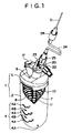
- 1 is a protective case consisting of a cylinder body 2 which is made in a cylindrical form having a bottom of transparent material such as plastic, glass, and so on, and of a lid body 5 which is engaged in the open end of the above-described cylinder body 2 and is formed from such material as polypropylene and so on.
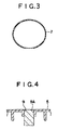
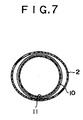
- the above-described cylinder body 2 is formed to have a cross sectional form as in Fig. 2 and is formed having a noncircular form, and specifically in this embodiment the cylinder body 2 is formed to be an elliptic form (refer to Fig. 3), formed to be a cylindrical form having a bottom of a curved convex surface, with a projection 3 being provided at the inner circumference wall of the open end side, while a division 4 is provided at the outer circumference wall.
- even-numbered divisions 4A which are 0, 20, 40, and 60 showing the amount of medical fluid contained (the amount of medical fluid contained in a rubber state elastic film 11 described below) in units of cc
- odd-numbered divisions 4B which are 10, 30, and 50 positioned between these even-numbered divisions, are provided at the position which is in an up-and-down direction from the center to the bottom portion.
- a concave portion for engagement 6 which is engaged in the projection 3 of the above-described cylinder body 2
- a medical fluid introduction tube 7 as a fluid introduction tube of a slender cylindrical form extending towards the inside of the above-described cylinder body 2, and an air hole 9 are respectively provided in a virtual center position of the top wall.
- the medical fluid introduction tube 7 has both ends open, and has a plurality of slits 8 which communicate the inside and outside, at its circumference surface.
- Fig. 4 illustrates, in the air hole 9, attached is a water repellent air filter 9A which circulates gas (air) inside and outside of the protection case 1 preventing the medical fluid from flowing.
- the water repellent air filter 9A for example, a filter made of a repel treated synthetic fiber and of medicine proof quality is preferable.
- a rubber state elastic film 11 of a tube form having a bottom with one end being opened is engaged so as to adhere closely, and the open end edge is held by a pinch 12 as a fixing tool.
- the external diameter and the length of the medical fluid introduction tube 7 is formed to be the size which is virtually equal to the into diameter and the length of the rubber state elastic film 11 when contracting.
- the maximum of 60 cc of medical fluid can be contained. It may be mentioned that in the case of medical fluid for cancer pain, about 20 cc is normally injected a day; therefore medical fluid for virtually three days can be contained.
- the rubber state film 11 expands as the medical fluid is injected and contained, and a spring 10 which extends as the rubber state elastic film 11 extends is positioned at the outer circumference.
- the spring 10 consisting of a wire rod of, for example, about a 0.6 to 0.8 mm line diameter, is coiled in a spiral state wherein the diameter becomes narrower as it goes downwards, with the top end being engaged in the above-described lid body 5, and furthermore the lowest end is abutted to the forward end of the medical fluid introduction tube 7 with the rubber state elastic film 11 between them.
- the above-described rubber state elastic film 11 is made from a tenacious and highly elastic material of medicine proof quality which is not easily damaged by the action of the medical fluid and so on, and transparent or semitransparent material is especially preferable.
- silicone rubber, and latex rubber currently on the market are preferable.
- the thickness is about 0.4 mm.
- the pressure of a 1000 to 7000 mm water column is preferable for the contraction ability when the medical fluid is contained in the rubber state elastic film 11. Normally, a vein of the human body is approximately a 60 mm water column; therefore by increasing the pressure, a patient can be given an injection.
- an inflow hole 19 as an inflow fluid hole through which the medical fluid is injected into the above-described rubber state elastic film 11, and an outflow hole 18 as an outflow fluid hole through which medical fluid contained in the above-described rubber state elastic film 11 is discharged are closely provided in a V-shaped form. That is to say, at the lid body 5, the inflow hole 19, the outflow hole 18, and the medical fluid introduction tube 7 which are communicated with one another are provided in a virtually Y-shaped form to be one body.
- a check valve 13 which permits the flow of the medical fluid into the medical fluid introduction tube 7 from the outside and prevents the flow of the medical fluid to the outside from the medical fluid introduction tube 7 is provided.
- the check valve 13 is provided with a valve sheath 15 which is laid within the inflow hole 19 and has a valve seat 14 at the midway position therein, and a valve rod 16 which is contained within the valve sheath 15 so as to be movable, opening and closing the valve seat 14, and is of medicine proof quality consisting of silicone rubber and so on.
- a cap 17 can be attached so as to be attachable and removable.
- a spiral flute 18A which engages a three-way valve 20 so as to be attachable and removable is formed around the above-described outflow hole 18.
- the three-way valve 20 includes a valve body 22 having three switchover valves 21A, 21B, and 21C, and a cock 23 which changes a flow route.
- a filter 26 which eliminates dust and so on in the medical fluid is contained within the connector 25.
- a connector 28 which is similar to the connector 25 is fixed at the other end of the tube 24, and at the forward end of this connector 28, an injector needle 31 as an instrument attached to the human body so as to be attachable and removable. Accordingly, the inside of the rubber sate elastic film 11 and the injector needle 31 as the instrument attached to the human body are connected through the thermoplastic tube 24 as means for controlling the flow.
- thermoplastic tube 24 As for the tube used as the thermoplastic tube 24, a single-layered tube is fine, or a tube which is coated, considering the reinforcement and handling, may be fine.
- material of the tube 24 polypropylene (PP), Polyethylene (PE), polyvinyl acetal (POM), polycarbonate (PC), ABS, polyamide resin, polystyrene (PS), and so on can be used, and transparent material is preferable.
- PP polypropylene
- PE Polyethylene
- POM polyvinyl acetal
- PC polycarbonate
- PS polyamide resin
- PS polystyrene
- coating material when coating flexible material is preferable, a thermoplastic resin elastomer can be used, and a polyolefin (LDPE, LLDPE) type elastomer, a thermoplastic polyurethan elastomer, a soft polyvinyl chloride resin, EVA, and so on can be used.
- LDPE polyolefin
- LLDPE polyolef
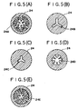
- a sectional form of an opening hole of the tube 24 has a different shaped opening hole, not that of a circular opening hole, and some of the examples are illustrated in Fig. 5 (A), Fig. 5 (B), Fig. (C), Fig. 5 (D), and Fig. 3 (E).
- an opening hole 24A of the tube 24 illustrated in Fig. 5 (A) is made to be the form wherein there are two different kinds of branches each of which has three projections alternately projected towards the center from the inner wall of the round-shaped basic hole.
- An opening hole 24B of the tube 24 illustrated in Fig. 5 (B) is made to be the form wherein virtual rectangular openings are extended at equally divided positions of 120 degrees from the center of the tube 24 in the radius direction, and are made to be the virtually Y-shaped form as a whole, with concaves and convexes being formed on the inner wall.
- An opening hole 24C illustrated in Fig. 5 (C) is made to be the form wherein the concaves and convexes are eliminated from the inner wall of Fig. 5 (B), and the length in the radius direction of each rectangular opening is shorter than in Fig. 5 (B).
- An opening hole 24D illustrated in Fig. 5 (D) is made to be the form wherein three of the slender triangle-shaped and round-shaped projections are alternately projected towards the center from the inner wall of the round-shaped basic hole.
- An opening hole 24E illustrated in Fig. 5 (E) is made to be the form wherein the form of the branch shaped projections are changed a little from that of Fig. 5 (A), and concaves and convexes which form a gear with inner cogs are provided on the inner wall of the basic hole of Fig. 5 (A).
- the manufacturing method of the above-described tube 24 in a form of a minute noncircular opening hole is forming by using the dies described in, for example, Japanese Patent Application Laid-open No. 51-21927. That is to say, the tube 24 in a form of the minute noncircular opening hole is obtained, by using monofilament dies which have a number of resin introduction holes within the range virtually equal to the outer diameter of the tube 24, and does not form a hole at the portion corresponding to the opening holes 24A to 24E, by pressing out a molten resin monofilament through this introduction hole, and by uniting a number of monofilaments which are close together.
- the manufacturing method of the tube 24 is not limited to this.
- the rubber state elastic film 11 touches the inner circumference wall of the cylinder body 2 of the protection case 1.
- the sectional form of the protection case 1 is formed to be the ellipse form as Fig. 7 illustrates, the square area where the rubber state elastic film 11 touches the protection case 1 can be made small compared to that of the circular form.
- the air flow is secured within the protection case 1, the air within the cylinder body 2 is discharged outside through the water repellent air filter 9A, with the expansion of the rubber state elastic film 11. Accordingly, the medical fluid is continuously, accurately supplied in a small amount, and the position to which the air hole 9 is attached is not limited.
- the valve seat 14 of the check valve 13 is closed. Accordingly, the medical fluid within the rubber state elastic film 11 does not leak outside.
- the injector needle 31 is attached to the connector 28 at the forward end of the tube 24, and this injector needle 31 is attached to the human body, when the cock 23 of the three-way valve 20 is opened, the medical fluid is successively introduced into the human body by a very small flow amount through the tube 24.
- the present invention is frequently used for the very small flow amount of about 0.8 ml/hr, however, the flow amount can be specified, according to the form and the length of the noncircular opening hole, and the viscosity of the medical fluid, and the flow amount is not limited to 0.8 ml/hr.
- the above-described embodiment has no need to provide the inflow hole 19 and outflow hole 18 at the cylinder body 2 side of the protection case 1; therefore, the above-described embodiment is easy to be contained in a pocket or the like, and conveniently carried, if this cylinder body is made to be a lower part.
- the bottom portion of the cylinder body 2 side is made to be a curved convex surface form, so that the above-described embodiment can be made compact and easy to be contained in a pocket, reducing the feeling of carrying a foreign object for the patients to whom it is given.
- the above-described embodiment which includes the inflow hole 19 and the outflow hole 18, can additionally introduce medical fluid into the rubber state elastic film 11 as it continues the injection of the medical fluid.
- the protection case 1, which consist of the cylinder body 2 and the lid body 5, is easy to assemble and disassemble.
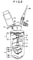
- the introduction and supply of the medical fluid can be conducted without hindrance, even when the inflow hole 19 and outflow hole 18 are closely positioned; therefore the whole body can be made compact. That is to say, as Fig. 6 illustrates, even when the syringe 41 is inserted into the valve sheath 15 of the check valve 13, the syringe 41 does not interfere with the three-way valve 20, and therefore the introduction and supply of the medical fluid can be conducted without hindrance. Furthermore, the introduction operation of the medical fluid can be conducted by holding the neck portions of the inflow hole 19 and outflow hole 18 between ones fingers; therefore the handling is easy.
- the medical fluid introduction tube 7 has the outer diameter and the length virtually equal to the inner diameter and the length of the rubber state elastic film 11 when contracting, as well as the slits on the outer circumference surface by which the inner portion is communicated with the inflow hole 19 and the outflow hole 18, communicating the inside and the outside, and the medical fluid supplied form the inflow hole 19 is introduced into the rubber state elastic film 11 from the forward end and the slits on the outer circumference surface of the medical fluid introduction tube 7, so that the load against the rubber state elastic film 11 does not become partial; therefore the durability of the rubber state elastic film 11 can be improved.
- the rubber state elastic film 11 is contracted to be in the state where it closely touches the outer surface of the medical fluid introduction tube 7; therefore the quantity of medical fluid remaining is small, when the supply is finished.
- the check valve 13 which permits the inflow of the medical fluid and prevents the outflow of the medical fluid is provided at the inflow hole 19
- the medical fluid can be introduced into the rubber state elastic film 11 through the check valve 13, and the medical fluid received within the rubber state elastic film 11 is prevented form flowing out of the inflow hole 19, and therefore the actual introduction of the medical fluid can be easily performed.
- the medical fluid within the rubber state elastic film 11 can be supplied from the tube 24 through the three-way valve 20 connected to the outflow hole 18 therefore the actual supplying of the medical fluid can be easily performed.
- the square area where the rubber state elastic film 11, expanded by the introduced medical fluid, contacts the inner wall of the cylinder body 2 can be made small, compared to that of the circular sectional form, and the air flow within the protection case 1 can be secured. Accordingly, the fluid can be continuously supplied accurately, and the position where the air hole 9 is provided is not limited. Moreover, the protection case 1 does not roll down even when it is placed on a tilted surface, and so the handling is easy. Of course, the medical fluid is prevented from flowing outside, even when the rubber state elastic film 11 is broken, since the rubber state elastic film 11 is sealed within the protection case 1. It is mentioned that in this connection the conventional apparatus for supplying the medical fluid, wherein the sectional form of the protection case is circular, is easy to roll down when placed on the tilted surface, and requires cautions when handling.
- the spring 10 of a spiral form, extending with the expansion of the rubber state elastic film 11, is engaged in the lid body 3, and the division 4 is provided at the outer circumference of the cylinder body 2; therefore the amount of the medical fluid contained within the rubber state elastic film 11 can be accurately determined from the relationship between the position to which the spring 10 extends, and the division 4.
- the square area where the rubber state elastic film 11, when expanded, contacts the protection case 1 can be made small, and the contraction of the rubber state elastic film 11 can be surely done by the function of the spring 10; therefore the amount of the medical fluid remaining is small when the supply is finished.
- the long sized thermoplastic resin tube 24 having the noncircular opening holes 24A to 24 E is used, instead of the short sized tube having the conventional circular opening hole; therefore a precise flow control can be attained by setting the form of the opening hole, and the length of the tube appropriately.
- the conventional tube with the circular opening hole is used as the introduction tube, the medical fluid in which dust larger than the inner diameter dimension is floating, or the medical fluid which easily solidifies does not flow at all, since the dust or the solidified substances block the entrance, however, the preferable embodiment uses the tube 24 of the noncircular opening hole form specified, so that the long sides of the noncircular opening holes 24A to 24E are not totally blocked by dust. Accordingly, even if an alien substance and solidified substance are in the medical fluid, the blockade of the opening holes 24A to 24E is more effectively prevented than with the conventional tube of a circular opening hole.
- the tube when the conventional circular opening hole tube is used as the introduction tube, the tube is bent, and blocked, because of the weight of a patient lying down, however, when the tube 24 of the noncircular opening hole of the preferable embodiment is used, the tube has resistance to bending, and is not blocked even when the weight falls on it; therefore it is safe. In the medical field where safety is given a priority, the apparatus for injecting the medical fluid which can not be blocked is important.
- the arrangement of the preferable embodiment, wherein the tube 24 possesses both the introduction function and the flow control function is simpler, compared to the arrangement of the apparatus wherein the conventional tube and the flow control means are combined.
- the preferable embodiment which specifies the tube 24 consisting of thermoplastic resin, makes it easy to manufacture the specified forms of the noncircular opening holes 24A to 24E, makes handling easy, and possesses control of a small flow amount and the introduction tube function.
- the preferable embodiment, wherein the rubber state elastic film 11 and the tube 24 which is a flow control means are respectively independent, making flow change easy, and able to cope with a wide range of very small flows by selecting and replacing the tube 24 of different forms of the noncircular opening holes and the lengths.
- the sectional form of the cylinder body 2 of the protection case 1 is made to be in the elliptic form, however it is not restrictive.
- the form of the outer circumference portion of the protection case 1 is also not limited to the elliptic form.
- the tube 24 is connected to the outflow hole 18 through the three-way valve 20, but it is not limited to the three-way valve 20, and a one-way opening and closing valve may be fine.
- the present invention can be used widely as an apparatus for injecting medical fluid not only for medical treatment in a vein, urology, obstetrics, gynecology, and so on, but also for injecting medical fluid, nutrients, and so on into a living body of an animal, fish and so on.
- the present invention can be used for supplying plants with water, nutrients (fluid), medical fluid (an insecticide fluid), and so on in small amounts.
- water, nutrients (fluid), and so on in small amounts.
- the medical fluid is injected into trees, it is fine if the protection case 1 is hung on the tree by an appropriate means, and the needle of the forward end of the tube 24 is inserted into the tree.
- This case is not limited to the case when the fluid flows out of the protection case 1 which is hanging in a downward direction, and the medical fluid can be injected into a position higher than the protection case 1.
- the present invention can be used in order to supply a fish aquarium with medical fluid such as an antibiotic and so on, bait (fluid), nutrients (fluid) for water plants and so on in small amounts.
- medical fluid such as an antibiotic and so on, bait (fluid), nutrients (fluid) for water plants and so on in small amounts.
- the apparatus for supplying fluid of the present invention which is convenient to hold and carry, can introduce an additional fluid as it continues to supply the fluid, can be arranged less expensively with the number of the parts being small, and can improve the durability and the handling.
- the effects of easy handling, and of supplying fluid accurately and continuously without limiting the position at which the air hole is provided are obtained.
Landscapes
- Health & Medical Sciences (AREA)
- Vascular Medicine (AREA)
- Engineering & Computer Science (AREA)
- Anesthesiology (AREA)
- Biomedical Technology (AREA)
- Heart & Thoracic Surgery (AREA)
- Hematology (AREA)
- Life Sciences & Earth Sciences (AREA)
- Animal Behavior & Ethology (AREA)
- General Health & Medical Sciences (AREA)
- Public Health (AREA)
- Veterinary Medicine (AREA)
- Infusion, Injection, And Reservoir Apparatuses (AREA)
- Catching Or Destruction (AREA)
- Loading And Unloading Of Fuel Tanks Or Ships (AREA)
- Farming Of Fish And Shellfish (AREA)
- Containers And Packaging Bodies Having A Special Means To Remove Contents (AREA)
- Nozzles (AREA)
Applications Claiming Priority (3)
| Application Number | Priority Date | Filing Date | Title |
|---|---|---|---|
| JP00889095A JP3499317B2 (ja) | 1995-01-24 | 1995-01-24 | 液体供給装置 |
| JP889095 | 1995-01-24 | ||
| JP8890/95 | 1995-01-24 |
Publications (2)
| Publication Number | Publication Date |
|---|---|
| EP0722745A1 true EP0722745A1 (fr) | 1996-07-24 |
| EP0722745B1 EP0722745B1 (fr) | 1999-12-29 |
Family
ID=11705280
Family Applications (1)
| Application Number | Title | Priority Date | Filing Date |
|---|---|---|---|
| EP96300441A Expired - Lifetime EP0722745B1 (fr) | 1995-01-24 | 1996-01-23 | Dispositif d'alimentation d'un fluide |
Country Status (6)
| Country | Link |
|---|---|
| EP (1) | EP0722745B1 (fr) |
| JP (1) | JP3499317B2 (fr) |
| KR (1) | KR100189709B1 (fr) |
| DE (1) | DE69605822T2 (fr) |
| ES (1) | ES2140024T3 (fr) |
| TW (1) | TW287111B (fr) |
Cited By (4)
| Publication number | Priority date | Publication date | Assignee | Title |
|---|---|---|---|---|
| EP0885620A3 (fr) * | 1997-06-19 | 1999-06-23 | Young Gyu Lee | Dispositif pour injecter des médicaments liquides |
| EP1086715A3 (fr) * | 1999-09-22 | 2002-01-02 | AuBEX CORPORATION | Régulateur de débit |
| US20180117244A1 (en) * | 2015-04-28 | 2018-05-03 | Sanofi-Aventis Deutschland Gmbh | Flexible Container for an Injection Device |
| CN113557934A (zh) * | 2021-07-29 | 2021-10-29 | 孙铭振 | 一种农业灌溉用滴灌用水除杂装置 |
Families Citing this family (6)
| Publication number | Priority date | Publication date | Assignee | Title |
|---|---|---|---|---|
| JP3566053B2 (ja) * | 1997-12-09 | 2004-09-15 | 大研医器株式会社 | ボウラス投与装置 |
| US5897530A (en) * | 1997-12-24 | 1999-04-27 | Baxter International Inc. | Enclosed ambulatory pump |
| WO2010144917A2 (fr) * | 2009-06-12 | 2010-12-16 | Arysta Lifescience North America, Llc | Contenant réutilisable pour produits chimiques dangereux |
| US11285261B2 (en) | 2018-10-11 | 2022-03-29 | Carefusion 303, Inc. | Syringe adapter |
| JP7295257B2 (ja) * | 2019-02-14 | 2023-06-20 | ダブリュ.エル.ゴア アンド アソシエイツ,インコーポレイティド | 水生環境における処理化合物の制御放出のための処理リザーバ及びシステム |
| JPWO2025018032A1 (fr) | 2023-07-18 | 2025-01-23 |
Citations (5)
| Publication number | Priority date | Publication date | Assignee | Title |
|---|---|---|---|---|
| WO1988003819A1 (fr) * | 1986-11-26 | 1988-06-02 | Infusion Systems Corporation | Distributeur de fluides sous pression |
| DE3940442A1 (de) * | 1989-11-21 | 1991-05-23 | Stefan Stellamanns | Dose zur aufbewahrung von durch druck ausgebbaren guetern oder stoffen |
| WO1992006721A1 (fr) * | 1990-10-23 | 1992-04-30 | Industrias Palex, S.A. | Dispositif portatif de perfusion a pression pour solutions medicamenteuses |
| US5167631A (en) * | 1991-09-17 | 1992-12-01 | Imed Corporation | Portable infusion device |
| US5360411A (en) * | 1992-10-12 | 1994-11-01 | Opto Tech Co., Ltd. | Liquid medicine injecting device |
-
1995
- 1995-01-24 JP JP00889095A patent/JP3499317B2/ja not_active Expired - Lifetime
-
1996
- 1996-01-23 EP EP96300441A patent/EP0722745B1/fr not_active Expired - Lifetime
- 1996-01-23 ES ES96300441T patent/ES2140024T3/es not_active Expired - Lifetime
- 1996-01-23 DE DE69605822T patent/DE69605822T2/de not_active Expired - Lifetime
- 1996-01-24 KR KR1019960001508A patent/KR100189709B1/ko not_active Expired - Lifetime
- 1996-02-13 TW TW085101783A patent/TW287111B/zh not_active IP Right Cessation
Patent Citations (5)
| Publication number | Priority date | Publication date | Assignee | Title |
|---|---|---|---|---|
| WO1988003819A1 (fr) * | 1986-11-26 | 1988-06-02 | Infusion Systems Corporation | Distributeur de fluides sous pression |
| DE3940442A1 (de) * | 1989-11-21 | 1991-05-23 | Stefan Stellamanns | Dose zur aufbewahrung von durch druck ausgebbaren guetern oder stoffen |
| WO1992006721A1 (fr) * | 1990-10-23 | 1992-04-30 | Industrias Palex, S.A. | Dispositif portatif de perfusion a pression pour solutions medicamenteuses |
| US5167631A (en) * | 1991-09-17 | 1992-12-01 | Imed Corporation | Portable infusion device |
| US5360411A (en) * | 1992-10-12 | 1994-11-01 | Opto Tech Co., Ltd. | Liquid medicine injecting device |
Cited By (6)
| Publication number | Priority date | Publication date | Assignee | Title |
|---|---|---|---|---|
| EP0885620A3 (fr) * | 1997-06-19 | 1999-06-23 | Young Gyu Lee | Dispositif pour injecter des médicaments liquides |
| EP1086715A3 (fr) * | 1999-09-22 | 2002-01-02 | AuBEX CORPORATION | Régulateur de débit |
| US6367502B1 (en) | 1999-09-22 | 2002-04-09 | Aubex Corporation | Flow control device |
| US20180117244A1 (en) * | 2015-04-28 | 2018-05-03 | Sanofi-Aventis Deutschland Gmbh | Flexible Container for an Injection Device |
| US11224690B2 (en) * | 2015-04-28 | 2022-01-18 | Sanofi-Aventis Deutschland Gmbh | Flexible container for an injection device |
| CN113557934A (zh) * | 2021-07-29 | 2021-10-29 | 孙铭振 | 一种农业灌溉用滴灌用水除杂装置 |
Also Published As
| Publication number | Publication date |
|---|---|
| TW287111B (fr) | 1996-10-01 |
| DE69605822T2 (de) | 2000-05-25 |
| JP3499317B2 (ja) | 2004-02-23 |
| ES2140024T3 (es) | 2000-02-16 |
| EP0722745B1 (fr) | 1999-12-29 |
| KR100189709B1 (ko) | 1999-06-01 |
| DE69605822D1 (de) | 2000-02-03 |
| KR960028892A (ko) | 1996-08-17 |
| JPH08196628A (ja) | 1996-08-06 |
Similar Documents
| Publication | Publication Date | Title |
|---|---|---|
| US5360411A (en) | Liquid medicine injecting device | |
| EP0427852B1 (fr) | Instrument muni d'un ballon employe pour injecter en continu un fluide medicinal | |
| US5211632A (en) | Infuser with balloon for infusing medicine | |
| EP0722745B1 (fr) | Dispositif d'alimentation d'un fluide | |
| EP0399117A2 (fr) | Injecteur continu pour médicament liquide | |
| JPH05123404A (ja) | 医療用カテーテル集成体 | |
| KR100610461B1 (ko) | 액체공급장치 | |
| JPH03218772A (ja) | 液体流出量制御部材及びその製造方法 | |
| EP1086715B1 (fr) | Régulateur de débit | |
| JP4028072B2 (ja) | 液体供給装置 | |
| EP0406822B1 (fr) | Valve pour le passage de liquides, destiner à des dispositifs médicinaux | |
| JP2001212233A (ja) | 液体供給チューブ | |
| CN1137736C (zh) | 液体供给装置 | |
| JP2568289B2 (ja) | バルーン付き薬液持続注入器 | |
| JPH04200563A (ja) | 液体流出量制御部材及びその製造方法 |
Legal Events
| Date | Code | Title | Description |
|---|---|---|---|
| PUAI | Public reference made under article 153(3) epc to a published international application that has entered the european phase |
Free format text: ORIGINAL CODE: 0009012 |
|
| AK | Designated contracting states |
Kind code of ref document: A1 Designated state(s): DE ES FR GB IT |
|
| 17P | Request for examination filed |
Effective date: 19970117 |
|
| 17Q | First examination report despatched |
Effective date: 19971112 |
|
| GRAG | Despatch of communication of intention to grant |
Free format text: ORIGINAL CODE: EPIDOS AGRA |
|
| GRAG | Despatch of communication of intention to grant |
Free format text: ORIGINAL CODE: EPIDOS AGRA |
|
| GRAH | Despatch of communication of intention to grant a patent |
Free format text: ORIGINAL CODE: EPIDOS IGRA |
|
| RAP1 | Party data changed (applicant data changed or rights of an application transferred) |
Owner name: OPTO TECH CO., LTD. Owner name: AUBEX CORPORATION |
|
| GRAH | Despatch of communication of intention to grant a patent |
Free format text: ORIGINAL CODE: EPIDOS IGRA |
|
| GRAH | Despatch of communication of intention to grant a patent |
Free format text: ORIGINAL CODE: EPIDOS IGRA |
|
| GRAA | (expected) grant |
Free format text: ORIGINAL CODE: 0009210 |
|
| RIN1 | Information on inventor provided before grant (corrected) |
Inventor name: SATO, HIDEYA Inventor name: KANAI, MASAHIRO |
|
| AK | Designated contracting states |
Kind code of ref document: B1 Designated state(s): DE ES FR GB IT |
|
| REF | Corresponds to: |
Ref document number: 69605822 Country of ref document: DE Date of ref document: 20000203 |
|
| ET | Fr: translation filed | ||
| ITF | It: translation for a ep patent filed | ||
| REG | Reference to a national code |
Ref country code: ES Ref legal event code: FG2A Ref document number: 2140024 Country of ref document: ES Kind code of ref document: T3 |
|
| PLBE | No opposition filed within time limit |
Free format text: ORIGINAL CODE: 0009261 |
|
| STAA | Information on the status of an ep patent application or granted ep patent |
Free format text: STATUS: NO OPPOSITION FILED WITHIN TIME LIMIT |
|
| 26N | No opposition filed | ||
| REG | Reference to a national code |
Ref country code: GB Ref legal event code: 732E |
|
| REG | Reference to a national code |
Ref country code: FR Ref legal event code: TP |
|
| REG | Reference to a national code |
Ref country code: ES Ref legal event code: PC2A |
|
| REG | Reference to a national code |
Ref country code: GB Ref legal event code: IF02 |
|
| REG | Reference to a national code |
Ref country code: FR Ref legal event code: PLFP Year of fee payment: 20 |
|
| PGFP | Annual fee paid to national office [announced via postgrant information from national office to epo] |
Ref country code: ES Payment date: 20141211 Year of fee payment: 20 |
|
| PGFP | Annual fee paid to national office [announced via postgrant information from national office to epo] |
Ref country code: IT Payment date: 20150114 Year of fee payment: 20 Ref country code: DE Payment date: 20150120 Year of fee payment: 20 |
|
| PGFP | Annual fee paid to national office [announced via postgrant information from national office to epo] |
Ref country code: FR Payment date: 20150108 Year of fee payment: 20 Ref country code: GB Payment date: 20150121 Year of fee payment: 20 |
|
| REG | Reference to a national code |
Ref country code: DE Ref legal event code: R071 Ref document number: 69605822 Country of ref document: DE |
|
| REG | Reference to a national code |
Ref country code: GB Ref legal event code: PE20 Expiry date: 20160122 |
|
| PG25 | Lapsed in a contracting state [announced via postgrant information from national office to epo] |
Ref country code: GB Free format text: LAPSE BECAUSE OF EXPIRATION OF PROTECTION Effective date: 20160122 |
|
| REG | Reference to a national code |
Ref country code: ES Ref legal event code: FD2A Effective date: 20160429 |
|
| PG25 | Lapsed in a contracting state [announced via postgrant information from national office to epo] |
Ref country code: ES Free format text: LAPSE BECAUSE OF EXPIRATION OF PROTECTION Effective date: 20160124 |