EP0722899B1 - Verfahren und Vorrichtung zum Ausgleich von Spannkräften über die Breite einer laufenden Bahn - Google Patents
Verfahren und Vorrichtung zum Ausgleich von Spannkräften über die Breite einer laufenden Bahn Download PDFInfo
- Publication number
- EP0722899B1 EP0722899B1 EP96100446A EP96100446A EP0722899B1 EP 0722899 B1 EP0722899 B1 EP 0722899B1 EP 96100446 A EP96100446 A EP 96100446A EP 96100446 A EP96100446 A EP 96100446A EP 0722899 B1 EP0722899 B1 EP 0722899B1
- Authority
- EP
- European Patent Office
- Prior art keywords
- shaft
- web
- roller
- bearing
- tension
- Prior art date
- Legal status (The legal status is an assumption and is not a legal conclusion. Google has not performed a legal analysis and makes no representation as to the accuracy of the status listed.)
- Expired - Lifetime
Links
Images


Classifications
-
- B—PERFORMING OPERATIONS; TRANSPORTING
- B65—CONVEYING; PACKING; STORING; HANDLING THIN OR FILAMENTARY MATERIAL
- B65H—HANDLING THIN OR FILAMENTARY MATERIAL, e.g. SHEETS, WEBS, CABLES
- B65H23/00—Registering, tensioning, smoothing or guiding webs
- B65H23/02—Registering, tensioning, smoothing or guiding webs transversely
-
- B—PERFORMING OPERATIONS; TRANSPORTING
- B65—CONVEYING; PACKING; STORING; HANDLING THIN OR FILAMENTARY MATERIAL
- B65H—HANDLING THIN OR FILAMENTARY MATERIAL, e.g. SHEETS, WEBS, CABLES
- B65H2403/00—Power transmission; Driving means
- B65H2403/50—Driving mechanisms
- B65H2403/52—Translation screw-thread mechanisms
-
- B—PERFORMING OPERATIONS; TRANSPORTING
- B65—CONVEYING; PACKING; STORING; HANDLING THIN OR FILAMENTARY MATERIAL
- B65H—HANDLING THIN OR FILAMENTARY MATERIAL, e.g. SHEETS, WEBS, CABLES
- B65H2404/00—Parts for transporting or guiding the handled material
- B65H2404/10—Rollers
- B65H2404/15—Roller assembly, particular roller arrangement
- B65H2404/152—Arrangement of roller on a movable frame
- B65H2404/1521—Arrangement of roller on a movable frame rotating, pivoting or oscillating around an axis, e.g. parallel to the roller axis
- B65H2404/15212—Arrangement of roller on a movable frame rotating, pivoting or oscillating around an axis, e.g. parallel to the roller axis rotating, pivoting or oscillating around an axis perpendicular to the roller axis
-
- B—PERFORMING OPERATIONS; TRANSPORTING
- B65—CONVEYING; PACKING; STORING; HANDLING THIN OR FILAMENTARY MATERIAL
- B65H—HANDLING THIN OR FILAMENTARY MATERIAL, e.g. SHEETS, WEBS, CABLES
- B65H2511/00—Dimensions; Position; Numbers; Identification; Occurrences
- B65H2511/20—Location in space
-
- B—PERFORMING OPERATIONS; TRANSPORTING
- B65—CONVEYING; PACKING; STORING; HANDLING THIN OR FILAMENTARY MATERIAL
- B65H—HANDLING THIN OR FILAMENTARY MATERIAL, e.g. SHEETS, WEBS, CABLES
- B65H2511/00—Dimensions; Position; Numbers; Identification; Occurrences
- B65H2511/20—Location in space
- B65H2511/21—Angle
- B65H2511/214—Inclination
-
- B—PERFORMING OPERATIONS; TRANSPORTING
- B65—CONVEYING; PACKING; STORING; HANDLING THIN OR FILAMENTARY MATERIAL
- B65H—HANDLING THIN OR FILAMENTARY MATERIAL, e.g. SHEETS, WEBS, CABLES
- B65H2511/00—Dimensions; Position; Numbers; Identification; Occurrences
- B65H2511/20—Location in space
- B65H2511/21—Angle
- B65H2511/216—Orientation, e.g. with respect to direction of movement
-
- B—PERFORMING OPERATIONS; TRANSPORTING
- B65—CONVEYING; PACKING; STORING; HANDLING THIN OR FILAMENTARY MATERIAL
- B65H—HANDLING THIN OR FILAMENTARY MATERIAL, e.g. SHEETS, WEBS, CABLES
- B65H2515/00—Physical entities not provided for in groups B65H2511/00 or B65H2513/00
- B65H2515/30—Forces; Stresses
-
- B—PERFORMING OPERATIONS; TRANSPORTING
- B65—CONVEYING; PACKING; STORING; HANDLING THIN OR FILAMENTARY MATERIAL
- B65H—HANDLING THIN OR FILAMENTARY MATERIAL, e.g. SHEETS, WEBS, CABLES
- B65H2515/00—Physical entities not provided for in groups B65H2511/00 or B65H2513/00
- B65H2515/30—Forces; Stresses
- B65H2515/32—Torque e.g. braking torque
Definitions
- the invention relates to a device for compensating clamping forces on the Width of a running web according to that mentioned in the preamble of claim 1 Art.
- Such a device is known from US Pat. No. 2,066,306 A. It consists of one Roller that is freely rotatable on a shaft. The shaft is at both ends guided in scenes and gripped by a lever linkage. This prevents one movement in the same direction of both shaft ends, so that the shaft and with it the roller is held pivotable only about an axis.
- this known device has the disadvantage that both in the scenes and in the lever linkage Swiveling the shaft sliding movements take place.
- the related Frictional forces limit the accuracy of what can be achieved with this device Voltage equalization. In particular, voltage compensation is not possible if the tension difference between both sides of the web is less than the considerable There is hate friction in the scenes and lever arm.
- the invention has for its object a device of the aforementioned To create a type that ensures precise compensation of tension across the width of the web, without hindering the web.
- the device according to claim 1 has a pivotally held tension compensation roller on This is freely rotatable on a shaft, the ends of which are in a pivot bearing are supported. This ensures that the space around the Tension compensation roller is free, so that the running of the web is not disturbed in any way is.
- the pivot bearing of the shaft is supported by the tension compensation roller on both sides provided toothed gear realized. Practice the web on the tension compensation roller torque off, this tries the tension compensation roller on the side of the higher clamping force in the direction of force.
- the toothed gear sets this movement of the tension compensation roller in one Rotation of the shaft around. This is in turn from the opposite gear in an opposite adjustment movement of the opposite end of the Wave implemented.
- This mechanism ensures that the tension balancing roller is only pivoted about an axis and not shifted overall can be. This in turn causes that with varying total clamping force the tension compensating roller does not reach any of its end stops. Of the Tension compensation across the width of the web is therefore among all occurring Operating conditions ensured.
- the application of toothed gears for Swiveling holding the shaft results in particularly low frictional forces since the teeth the toothed gear gripping each other without sliding against each other.
- the shaft ends are supported in the scenes via roller bearings, which are located on the scenes pass on. In this way, frictional forces emanating from the scenes largely suppressed.
- the one for pivoting the tension compensation roller The force required is therefore very low, so that the tension compensation of the web even without active adjustment of the tension compensation roller solely by that of the Railway transmitted torque can take place.
- the desired clamping force compensation is therefore achieved particularly inexpensively with the simplest of means. Also lets the device build very compact, so that existing systems through simple replacement of a roller can be converted without problems.
- ball or roller bearings have proven themselves as rolling bearings. This have very favorable running properties, especially those for an exact Tension compensation harmful friction force is negligible. That ball or Roller bearing is only on one side of a rail or column as a counter bearing and rolls on it. This counter bearing limits the freedom of movement of the tension compensation roller on one level. This prevents pivoting of the Tension compensation roller around a perpendicular to the desired swivel axis Axis that would result in a lateral path. In addition, the counter bearing a correct position of the parts of the toothed gear, so that its teeth always interlock correctly.
- the rack and pinion one To form gear.
- the gear meshes directly with the rack, which minimizes the friction losses of the swivel bearing. Since the rack is fixed, the gear must turn on when adjusting the tension compensation roller roll this, whereby the gear is rotated together with the shaft.
- the racks are on both ends of the shaft at diagonally opposite Provided sides of the shaft axis. This causes the adjustment of the Shaft ends are synchronized in opposite directions to each other.
- the tension compensation roller can therefore only be pivoted about a fixed, predetermined pivot axis, the gear meshing with the rack through the center of gravity of the tension compensation roller runs.
- the racks could be the same Side of the shaft axis can be provided. In this case one of the toothed gears would have to have an intermediate gear that reverses the rotational movement of this side. To minimize the frictional forces between the gear and the rack it is convenient to equip them with involute or cycloid teeth.
- the tension compensation roller can be easily turned by turning the threaded spindle or adjust the screw in its altitude.
- the actuators it is favorable to connect the actuators to a control device.
- the control device receives its actual value from force measuring devices which are in the bearings of a roller are provided.
- the measured force values are over subtracted from each other, the output value of which from the web torque exerted on the tension compensation roller is proportional.
- This Value is regulated by the control device to the setpoint zero, so that in the steady state State of the control device the tension forces of the web in both Web halves are equal to each other. Because the pivoting of the tension compensation roller actively done through the regulation, play frictional influences, as well the inertia of the tension compensation roller for tension compensation only a subordinate role. They only limit the speed at which one Clamping force difference is corrected.
- the accuracy of the clamping force compensation is exclusively from the precision of the detection of the web on the tension compensation roller exerted torque and the quality of the controller.
- the bearing forces of one of the rollers are measured and their difference calculated.
- the difference in the bearing forces of both ends of a roller is with a central web run, proportional to the torque that the web has on the roller exercises.
- the roller's bearing forces can be particularly easily and precisely adjusted by in determine the force measuring devices provided in the bearings.
- the Bearing forces determined on the tension compensation roller This ensures that the The tension of the web is correctly unaffected by the friction of other rollers is detected. It also eliminates time delays between the pivoting of the tension compensation roller and the effect on it Tension of the web is reduced to a minimum.
- the scheme can therefore Compensate any tension difference of the web faster.
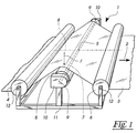
- Figure 1 shows a device 1 for compensating clamping forces across the width a path 3 running in the direction of arrow 2.
- This path 3 is on in bearings 12 held rollers 4, 5, 6 deflected, the middle roller 5 as a tension compensation roller is trained.
- the tension compensation roller 5 is freely rotatable a shaft 7 mounted about a pivot axis extending through its center of gravity S. 8 is pivotally held. Both ends 9 of the shaft 7 are supported in bearings 10, which are held on a frame 11 and together a pivot bearing for the Form wave 7.
- Figure 2 shows the bearing 10 consisting of a housing block 15, the Cover is removed.
- a stationary one Threaded spindle 16 This meshes with a gear 17, the teeth 18 only is indicated.
- the gear 17 is connected to the shaft 7 in a rotationally fixed manner.
- the web 3 presses the shaft 7 with a force F and tries to drive it to move in that direction. Since the gear 17 with the threaded spindle 16 combs, it must roll on this displacement on the threaded spindle 16, so that it is simultaneously rotated in direction 19.
- the shaft 7 is held in mirror image to the representation according to Figure 2. This causes the described rotation 19 of the gear 17 and thus the shaft 7 at its opposite end 9 is a displacement directed against the force F. causes.
- the movements of the ends 9 of the shaft 7 are therefore opposite to each other synchronized so that the shaft 7 and thus the voltage compensation roller 5 only is pivotable about the pivot axis 8 indicated in FIG.
- FIG. 3 shows the bearing 10 according to FIG. 2, the gear wheel 17 with the shaft 7 removed to see the parts underneath.
- the housing block 15 are defined at a distance e two columns 20, the guide for the shaft 7 form.
- the shaft 7 carries a roller bearing 21, which alone and only with its Receiving opening 22 is shown.
- the roller bearing 21 runs between the columns 20, whose distance e from each other is slightly larger than the outer diameter D of Rolling bearing is. This ensures that the roller bearing 21 only on one of the two Columns 20 abuts and rolls on it without sliding.
- the backdrop guide causes that the shaft 7 can only move within one plane ⁇ .
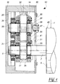
- FIG. 10 An alternative embodiment of the bearing 10 is shown in FIG. It exists from the housing block 15, on which a cover 30 is fixed.
- the cover 30 has an opening 31 penetrated by the shaft 7.
- the shaft 7 is by means of Rolling bearing 21 is supported on the columns 20 and rotatably connected to the gear 17.
- the gear 17 meshes with an intermediate gear 32, the shaft 33 via further roller bearing 34 is also supported on the columns 20.
- the waves 7, 33 are Supported via roller bearings 35 on a cage 36, the mutual distance M between the shaft axis 23 and the shaft axis 37 keeps constant.
- the two Rolling bearings 21, 34 allow the cage 36 to move up and down in the direction force F. However, they prevent sideways movement and swiveling of the cage 36.
- a stop 38 is provided which presses against the shaft 33.
- the Ball 39 held resiliently.
- the stop 38 limits the movement of the cage 36 only in one direction, but at the opposite end 9 of the shaft 7 there is another Bearing 10 provided diagonally opposite bearing, the movement of there provided cage 36 limited in the opposite direction. Since both cages 36 with the Shaft 7 are connected, is a movement of the shaft 7 in the direction of its longitudinal axis 23 excluded.
- a braking device 41 is provided on the carriage 36. It works against them Shaft 7 and prevents its rotation relative to the cage in the tightened position 36. In the released position, the braking device 41 is spaced from the shaft 7, so that the tension compensation roller 5 can pivot freely.
- FIG. 5 shows an alternative embodiment of the device 1 with active adjustment the tension compensation roller 5.
- the basic structure corresponds to the Device 1 according to Figure 1, wherein the shaft 7 against rotation about its Longitudinal axis 23 is blocked.
- the threaded spindles 16 of the bearings 10 are with actuators 50 connected. These can, for example, be flanged electric motors Gearboxes or hydraulic motors.
- the actuators 50 offset the threaded spindles 16 in rotation and thus cause a height adjustment of the ends 9 of the shaft 7.
- the actuators 50 are in operative connection with displacement sensors 51 which detect the adjustment path of the threaded spindle 16.
- the actuators 50, the displacement sensors 51, the edge measuring devices 52 and the edge sensors 54 are operatively connected to a control device 55.
- This control device 55 has the task of adjusting differences in tension in both web halves by adjusting to compensate for the tension compensation roller 5.
- a totalizer 56 is on the input side in operative connection with the force measuring devices 52 and calculates the Difference of the measured bearing forces, which is proportional to that of the web 3 on the Tension compensation roller 5 is exerted torque.
- the output signal of the Totalizer 56 is fed to a controller 58 via a further totalizer 57, which preferably has a P, PI or PID behavior.
- the one obtained from controller 58 Correction signal is a non-inverting input 59 and a inverting input 60 supplied by summers 61, 62, which are not shown Power amplifiers are operatively connected to the actuators 50.
- This control loop is used when there is a difference in bearing force between the ends 9 of the shaft 7 causes an opposite height adjustment of the shaft 7, so this panned. Constantly about the position of the pivot axis 8 of the shaft 7 hold, the average of the adjustment paths from the ends 9 of the tension compensation roller 5 regulated.
- the displacement sensors 51 are equipped with a further summer 63 connected, whose output signal is the average of the adjustment paths of both Ends 9 of the shaft 7 is proportional.
- This signal is in a further controller 64 regulated to a constant setpoint.
- the controller 64 also preferably has a P-, PI or PID behavior.
- the correction signal obtained from controller 64 arrives non-inverting inputs 65, 66 of the summers 61, 62 and therefore causes one Adjustment of both ends 9 of the shaft 7 in the same direction the middle position of the tension compensation roller 5 and thus the position of its Pivot axis 8 held.
- the signal f calculated by the circuit block 68 is also multiplied in a multiplier 69 a signal multiplied by the total of the web 3 on the tension compensation roller 5 corresponds to the force exerted.
- This signal is from a summer 70 won, the input side with the force measuring devices 52 in operative connection stands.
- the summer 70 is connected via an inverting input 71 connected to a coefficient element 72, by means of which the weight of the tension compensation roller 5 from those measured by the force measuring devices 52 Values is subtracted.
- the multiplier 69 calculates that difference in force between the two Ends of the shaft 7, which is caused by the off-center web run. This Value is fed to an inverting input 73 of the summer 57, so that on Output 74 of the summer 57 is proportional to the tension difference between the two web halves Signal pending.
- a window comparator 75 is connected to the output 74 of the summer 57 and compares the control deviation with two fixed limit values. At a digital output 76 of the window comparator 75 is at a zero level when the control deviation is within the range between the limits. The digital output 76 is operatively connected to a hold input 77 of the controller 58, which is in the Inactive in the event of a zero level. This is important so that integrators in controller 58 do not accept undefined output values. Output 76 is also available a braking device of the bearing 10 in operative connection, which is pending at one level the shaft 7 blocked from rotation about its longitudinal axis, so that the actuators 50 can adjust the tension compensation roller 5.
- the control device 55 can be implemented by analog or digital arithmetic circuits will.
- implementation using a microcomputer is advantageous because in this case additional functions and changes to the control algorithms can be easily taken into account by adapting the program.
Landscapes
- Controlling Rewinding, Feeding, Winding, Or Abnormalities Of Webs (AREA)
- Registering, Tensioning, Guiding Webs, And Rollers Therefor (AREA)
Description
- Figur 1
- eine perspektivische Darstellung einer Vorrichtung zum Ausgleich von Spannkräften einer Bahn,
- Figur 2
- eine perspektivische Darstellung einer Seite einer Schwenklagerung,
- Figur 3
- die Schwenklagerung gemäß Figur 2 ohne Zahnrad,
- Figur 4
- eine Schnittdarstellung einer alternativen Ausführungsform einer Seite eines Schwenklagers mit verschobener Schwenkachse und
- Figur 5
- eine Vorrichtung zum Ausgleich von Spannkräften einer Bahn mit aktiver Regelung.
- 1
- Vorrichtung
- 2
- Bahnlaufrichtung
- 3
- Bahn
- 4
- Walze
- 5
- Spannungs-Ausgleichswalze
- 6
- Walze
- 7
- Welle
- 8
- Schwenkachse
- 9
- Ende
- 10
- Lager
- 11
- Gestell
- 12
- Lager
- 15
- Gehäuseblock
- 16
- Gewindespindel
- 17
- Zahnrad
- 18
- Verzahnung
- 19
- Drehrichtung
- 20
- Säule
- 21
- Wälzlager
- 22
- Öffnung
- 23
- Achse
- 24
- Durchgangsbohrung
- 30
- Deckel
- 31
- Öffnung
- 32
- Zwischenzahnrad
- 33
- Welle
- 34,35
- Wälzlager
- 36
- Käfig
- 37
- Achse
- 38
- Anschlag
- 39
- Kugel
- 40
- Mantelfläche
- 41
- Bremsvorrichtung
- 50
- Stellantrieb
- 51
- Weggeber
- 52
- Kraftmeßvorrichtung
- 53
- Bahnkante
- 54
- Kantenfühler
- 55
- Regeleinrichtung
- 56, 57
- Summierer
- 58
- Regler
- 59
- nicht invertierender Eingang
- 60
- invertierender Eingang
- 61,62,63
- Summierer
- 64
- Regler
- 65,66
- nicht invertierender Eingang
- 67
- Korrekturvorrichtung
- 68
- Schaltungsblock
- 69
- Multiplizierer
- 70
- Summierer
- 71
- invertierender Eingang
- 72
- Koeffizientenglied
- 73
- invertierender Eingang
- 74
- Ausgang
- 75
- Fensterkomparator
- 76
- Digitalausgang
- 77
- Halteeingang
- a, b
- Abstand der Bahnkante von den Kraftmeßvorrichtungen
- D
- Außendurchmesser
- e
- Abstand der Säulen
- F
- Kraft
- L
- Abstand
- S
- Schwerpunkt
- ε
- Ebene
Claims (10)
- Vorrichtung zum Ausgleich von Spannkräften über die Breite einer über Walzen (4, 5, 6) gezogenen Bahn (3), vorzugsweise einer Papier- oder Folienbahn, mit einer die Bahn (3) umlenkenden, frei drehbaren, auf einer um ihre Längsachse (23) verdrehbaren Welle (7) gelagerten Spannungs-Ausgleichswalze (5), wobei die Welle (7) in einer Schwenklagerung (10) abgestützt ist, die in einem Gestell (11) gehalten ist, und die Welle (7) beidseits der Spannungs-Ausgleichswalze (5) die Bewegung ihrer beiden Enden gegensinnig koppelnd gehalten und in Kulissen (20) geführt ist, dadurch gekennzeichnet, daß die Welle (7) beidseits der Spannungs-Ausgleichswalze (5) durch Zahngetriebe (16, 17, 32) bewegbar gehalten und in den Kulissen (20) über Wälzlager (21) abgestützt ist.
- Vorrichtung nach Anspruch 1, dadurch gekennzeichnet, daß das Wälzlager (21) ein auf der Welle (7) festgelegtes Kugel- oder Rollenlager ist, das sich an einer Schiene oder Säule (20) als Gegenlager abstützt.
- Vorrichtung nach Anspruch 1, dadurch gekennzeichnet, daß das Zahngetriebe (16, 17, 32) von einer Zahnstange (16) gebildet ist, die mit einem drehfest mit der Welle (7) verbundenen Zahnrad (17) in Wirkverbindung steht.
- Vorrichtung nach Anspruch 3, dadurch gekennzeichnet, daß zwischen der Zahnstange (16) und dem Zahnrad (17) der Welle (7) als Wirkverbindung ein Zwischenzahnrad (32) vorgesehen ist.
- Vorrichtung nach Anspruch 4, dadurch gekennzeichnet, daß die Achse (37) des Zwischenzahnrades (32) mit der Mantelfläche (40) der Spannungs-Ausgleichswalze (5)fluchtet.
- Vorrichtung nach mindestens einem der Ansprüche 3 bis 5, dadurch gekennzeichnet, daß die Zahnstange (16) als Gewindespindel oder Schnecke ausgebildet ist.
- Vorrichtung nach Anspruch 6, dadurch gekennzeichnet, daß an beiden Gewindespindeln (16) oder Schnecken miteinander gegensinnig gekoppelte Stellantriebe (50) angreifen, und die Welle (7) gegenüber einer Verdrehung um ihre Längsachse (23) verblockt ist.
- Vorrichtung nach Anspruch 7, dadurch gekennzeichnet, daß die Stellantriebe (50) mit einer Regeleinrichtung (55) in Wirkverbindung stehen, welche zumindest von an den Lagern (12) einer der Walzen (4, 5, 6), vorzugsweise der Spannungs-Ausgleichswalze (5), vorgesehenen Kraftmeßvorrichtungen (52) beeinflußt ist.
- Vorrichtung nach Anspruch 8, dadurch gekennzeichnet, daß die Regeleinrichtung (55) von mindestens einem die Lage der Bahnkante (53) erfassenden Kantenfühler (54) beeinflußt ist.
- Vorrichtung nach Anspruch 8, dadurch gekennzeichnet, daß die Kraftmeßeinrichtungen (52) mit einem Fensterkomparator (75) in Wirkverbindung stehen, der das von der Bahn (3) auf die Spannungs-Ausgleichswalze (5) ausgeübte Drehmoment mit einem zwischen zwei Grenzwerten liegenden Bereich vergleicht, wobei die Spannungs-Ausgleichswalze (5) bei Drehmomenten innerhalb des Bereichs frei schwenkbar gehalten und sonst von den Stellantrieben (50) in ihrer Lage geregelt ist.
Priority Applications (1)
| Application Number | Priority Date | Filing Date | Title |
|---|---|---|---|
| EP98109833A EP0888993B1 (de) | 1995-01-20 | 1996-01-13 | Verfahren und Vorrichtung zum Ausgleich von Spannkräften über die Breite einer laufenden Bahn |
Applications Claiming Priority (2)
| Application Number | Priority Date | Filing Date | Title |
|---|---|---|---|
| DE19501644 | 1995-01-20 | ||
| DE19501644A DE19501644C2 (de) | 1995-01-20 | 1995-01-20 | Verfahren und Vorrichtung zum Ausgleich von Spannkräften über die Breite einer laufenden Bahn |
Related Child Applications (1)
| Application Number | Title | Priority Date | Filing Date |
|---|---|---|---|
| EP98109833A Division EP0888993B1 (de) | 1995-01-20 | 1996-01-13 | Verfahren und Vorrichtung zum Ausgleich von Spannkräften über die Breite einer laufenden Bahn |
Publications (3)
| Publication Number | Publication Date |
|---|---|
| EP0722899A2 EP0722899A2 (de) | 1996-07-24 |
| EP0722899A3 EP0722899A3 (de) | 1997-07-02 |
| EP0722899B1 true EP0722899B1 (de) | 1998-12-16 |
Family
ID=7751922
Family Applications (2)
| Application Number | Title | Priority Date | Filing Date |
|---|---|---|---|
| EP96100446A Expired - Lifetime EP0722899B1 (de) | 1995-01-20 | 1996-01-13 | Verfahren und Vorrichtung zum Ausgleich von Spannkräften über die Breite einer laufenden Bahn |
| EP98109833A Expired - Lifetime EP0888993B1 (de) | 1995-01-20 | 1996-01-13 | Verfahren und Vorrichtung zum Ausgleich von Spannkräften über die Breite einer laufenden Bahn |
Family Applications After (1)
| Application Number | Title | Priority Date | Filing Date |
|---|---|---|---|
| EP98109833A Expired - Lifetime EP0888993B1 (de) | 1995-01-20 | 1996-01-13 | Verfahren und Vorrichtung zum Ausgleich von Spannkräften über die Breite einer laufenden Bahn |
Country Status (5)
| Country | Link |
|---|---|
| US (1) | US5663510A (de) |
| EP (2) | EP0722899B1 (de) |
| JP (1) | JP2996908B2 (de) |
| CA (1) | CA2167466C (de) |
| DE (3) | DE19501644C2 (de) |
Cited By (1)
| Publication number | Priority date | Publication date | Assignee | Title |
|---|---|---|---|---|
| CN107804732A (zh) * | 2016-09-09 | 2018-03-16 | 株式会社Ihi | 张力分布控制装置及带状体搬运装置 |
Families Citing this family (38)
| Publication number | Priority date | Publication date | Assignee | Title |
|---|---|---|---|---|
| DE19740222A1 (de) | 1997-09-12 | 1999-03-25 | Boewe Systec Ag | Vorrichtung zum Führen einer Endlospapierbahn |
| FI104161B (fi) | 1998-02-17 | 1999-11-30 | Valmet Corp | Menetelmä ja laitteisto rainan rullauksessa |
| FI104762B (fi) * | 1998-07-01 | 2000-03-31 | Valmet Automation Inc | Menetelmä ja laitteisto liikkuvan rainan kireyden mittaamiseksi |
| US5996195A (en) * | 1998-07-20 | 1999-12-07 | Morrison Berkshire, Inc. | Cross machine tensioning system and method |
| US6325895B1 (en) * | 2000-06-12 | 2001-12-04 | Voith Sulzer Paper Technology North America, Inc. | Paper-making machine with an air press belt run |
| DE10202798B4 (de) * | 2002-01-25 | 2004-03-04 | Man Roland Druckmaschinen Ag | Vorrichtung zum Verstellen von bahnführenden Walzen |
| US7415881B2 (en) * | 2004-08-19 | 2008-08-26 | Fife Corporation | Ultrasonic sensor system for web-guiding apparatus |
| DE102005028333B4 (de) * | 2005-06-18 | 2013-05-02 | Koenig & Bauer Aktiengesellschaft | Tänzerwalzensystem |
| DE102005034445A1 (de) | 2005-07-23 | 2007-01-25 | GM Global Technology Operations, Inc., Detroit | Vorderbau für ein Kraftfahrzeug |
| US20080066594A1 (en) * | 2006-09-15 | 2008-03-20 | The Boeing Company. | Punch roller bypass unit |
| US8720333B2 (en) * | 2007-04-26 | 2014-05-13 | Hewlett-Packard Development Company, L.P. | Buffering and tension control system and method |
| EP2070853A1 (de) | 2007-12-10 | 2009-06-17 | Fife-Tidland GmbH | Brücke einer Wellpappenanlage |
| DE102009047776B4 (de) * | 2009-09-30 | 2012-04-26 | Eastman Kodak Co. | Verfahren und Vorrichtung zum Messen einer Laufrichtung einer Substratbahn |
| CN102707497B (zh) * | 2011-11-15 | 2014-08-06 | 京东方科技集团股份有限公司 | 一种摩擦布检查机及摩擦布检查方法 |
| DE102013000250A1 (de) * | 2013-01-09 | 2014-07-10 | Kuka Laboratories Gmbh | Konfigurierbare Sicherheitsüberwachung für eine Roboteranordnung |
| US9415963B2 (en) | 2013-01-30 | 2016-08-16 | Fife Corporation | Sensor controller for interpreting natural interaction sensor for web handling |
| CN103204401A (zh) * | 2013-04-27 | 2013-07-17 | 四川制药制剂有限公司 | 便于拆卸的铝箔张紧装置 |
| CN103318677B (zh) * | 2013-07-02 | 2015-11-25 | 金东纸业(江苏)股份有限公司 | 一种压光机及利用该压光机调整纸幅的方法 |
| KR200474021Y1 (ko) * | 2014-03-25 | 2014-08-14 | 홍순승 | 텐션조절장치 |
| KR200474022Y1 (ko) * | 2014-03-25 | 2014-08-14 | 홍순승 | 텐션조절장치 |
| US9372127B1 (en) | 2015-05-04 | 2016-06-21 | Eastman Kodak Company | Printing system controlled using photoelastic measurement device |
| US9372128B1 (en) | 2015-05-04 | 2016-06-21 | Eastman Kodak Company | Printing defect detection using photoelastic measurement device |
| CN106395452A (zh) * | 2015-11-11 | 2017-02-15 | 华巧波 | 一种卷布机 |
| CN106743899A (zh) * | 2017-03-02 | 2017-05-31 | 佛山市丰泽纺织有限公司 | 一种洗水拉斜烘干预缩机用光电自动对中机 |
| CN108677002B (zh) * | 2018-05-16 | 2019-08-23 | 山西太钢不锈钢股份有限公司 | 一种适用于连轧卧式退火炉的炉内张力补偿控制方法 |
| CN108772424B (zh) * | 2018-07-17 | 2024-07-23 | 桂林电子科技大学 | 成品铝箔板形离线动态检测自动控制系统及其使用方法 |
| CN109230740A (zh) * | 2018-08-01 | 2019-01-18 | 北京龙马负图科技有限公司 | 一种手动压力绷带张力调节指示装置 |
| US20220002107A1 (en) * | 2020-07-01 | 2022-01-06 | CSG Holding, Inc. | Webtension transducer load cell with integrated data interface |
| CN112938593A (zh) * | 2021-02-01 | 2021-06-11 | 安徽理工大学 | 一种耐磨性强的吸汗布料的加工工艺及其加工装置 |
| IT202200009695A1 (it) | 2022-05-11 | 2023-11-11 | Fosber Spa | Un dispositivo per regolare ed equalizzare la tensione in un materiale nastriforme, e un ondulatore comprendente detto dispositivo |
| CN116180371B (zh) * | 2022-12-21 | 2023-09-01 | 连云港鹰游新立成纺织科技有限公司 | 一种便于展平的纺织布料定型机及其使用方法 |
| CN117104969A (zh) * | 2023-09-15 | 2023-11-24 | 德州鑫泽复合材料有限公司 | 一种复合材料予浸机原料分离装置及分离方法 |
| CN116929935B (zh) * | 2023-09-18 | 2023-12-12 | 常州市武进广宇花辊机械有限公司 | 一种无纺布纺粘成网缺陷检测装置及检测方法 |
| CN117088048B (zh) * | 2023-10-07 | 2024-03-08 | 上海赛摩物流科技有限公司 | 一种用于输送线的链条智能自动张紧机构 |
| CN117388461B (zh) * | 2023-12-07 | 2024-03-12 | 北京一控系统技术有限公司 | 箔材离线板形检测装置及检测方法 |
| CN118723652B (zh) * | 2024-09-03 | 2024-12-06 | 浙江洲一铝业有限公司 | 一种铝箔收卷用卷绕纠偏装置 |
| CN119218804B (zh) * | 2024-12-03 | 2025-03-04 | 安徽如领新材料科技有限公司 | 一种电子玻璃柔性间隔膜收卷设备 |
| CN121157266B (zh) * | 2025-11-05 | 2026-04-17 | 江苏海时益新材料科技有限公司 | 一种缠绕膜压延生产设备 |
Family Cites Families (19)
| Publication number | Priority date | Publication date | Assignee | Title |
|---|---|---|---|---|
| US2066306A (en) * | 1932-05-21 | 1936-12-29 | Hoe & Co R | Web guiding roller support |
| US2066307A (en) * | 1935-06-07 | 1936-12-29 | Hoe & Co R | Web feeding mechanism |
| DE1057016B (de) * | 1957-02-26 | 1959-05-06 | Sundwiger Eisen Maschinen | Vorrichtung zum seitlich lagerichtigen Zufuehren eines unter einer Zugspannung stehenden Bandes |
| US3260106A (en) * | 1964-02-18 | 1966-07-12 | Moore Business Forms Inc | Web tension meter |
| GB1334011A (en) * | 1971-07-05 | 1973-10-17 | Victory Kidder Ltd | Web tension devices |
| US4130014A (en) * | 1977-10-11 | 1978-12-19 | W. J. Industries, Incorporated | Tension monitor means |
| US4326424A (en) * | 1979-03-30 | 1982-04-27 | Cleveland Machine Controls, Inc. | Web tension transducer arrangement |
| FR2458501B1 (fr) * | 1979-06-08 | 1986-03-21 | Astin France | Dispositif de regulation de la tension d'une bande en defilement |
| DD148620A1 (de) * | 1980-01-16 | 1981-06-03 | Harald Moews | Vorrichtung zur kantenkorrektur laufender bahnen,vorzugsweise fuer folien |
| US4549701A (en) * | 1983-12-16 | 1985-10-29 | Beloit Corporation | Web tension load cell |
| DE3428707A1 (de) * | 1984-08-03 | 1986-02-13 | MWB Messwandler-Bau AG, 8600 Bamberg | Vorrichtung fuer bandwickelmaschinen zum ausgleich eines einseitigen bandzuges |
| DD228234A1 (de) * | 1984-08-20 | 1985-10-09 | Polygraph Leipzig | Vorrichtung zur messung der bahnspannung |
| US4735102A (en) * | 1986-03-07 | 1988-04-05 | Cleveland Machine Controls, Inc. | Web tension transducer apparatus |
| US4691579A (en) * | 1986-06-03 | 1987-09-08 | Ekola Kenneth E | Tension transducer |
| US4899599A (en) * | 1987-12-07 | 1990-02-13 | Magnetic Power Systems, Inc. | Strain force sensor means |
| JPH0798604B2 (ja) * | 1988-06-21 | 1995-10-25 | 株式会社東京機械製作所 | 張力検出装置及び張力制御装置 |
| US5020381A (en) * | 1990-02-20 | 1991-06-04 | Bartlett Edward C | Web tension monitor |
| US5257550A (en) * | 1990-11-01 | 1993-11-02 | The Montalvo Corporation | Web tension sensor |
| US5275062A (en) * | 1991-08-09 | 1994-01-04 | T. Sendzimir, Inc. | Web tension measuring device for use with web coiling equipment |
-
1995
- 1995-01-20 DE DE19501644A patent/DE19501644C2/de not_active Expired - Fee Related
-
1996
- 1996-01-13 DE DE59600976T patent/DE59600976D1/de not_active Expired - Lifetime
- 1996-01-13 EP EP96100446A patent/EP0722899B1/de not_active Expired - Lifetime
- 1996-01-13 EP EP98109833A patent/EP0888993B1/de not_active Expired - Lifetime
- 1996-01-13 DE DE59604001T patent/DE59604001D1/de not_active Expired - Lifetime
- 1996-01-16 US US08/585,458 patent/US5663510A/en not_active Expired - Lifetime
- 1996-01-17 CA CA002167466A patent/CA2167466C/en not_active Expired - Lifetime
- 1996-01-22 JP JP8008241A patent/JP2996908B2/ja not_active Expired - Fee Related
Cited By (2)
| Publication number | Priority date | Publication date | Assignee | Title |
|---|---|---|---|---|
| CN107804732A (zh) * | 2016-09-09 | 2018-03-16 | 株式会社Ihi | 张力分布控制装置及带状体搬运装置 |
| CN107804732B (zh) * | 2016-09-09 | 2019-07-09 | 株式会社Ihi | 张力分布控制装置及带状体搬运装置 |
Also Published As
| Publication number | Publication date |
|---|---|
| CA2167466C (en) | 1999-05-11 |
| US5663510A (en) | 1997-09-02 |
| CA2167466A1 (en) | 1996-07-21 |
| EP0888993A1 (de) | 1999-01-07 |
| DE59600976D1 (de) | 1999-01-28 |
| EP0722899A3 (de) | 1997-07-02 |
| DE19501644C2 (de) | 1998-02-19 |
| DE59604001D1 (de) | 2000-01-27 |
| JPH08225206A (ja) | 1996-09-03 |
| EP0888993B1 (de) | 1999-12-22 |
| JP2996908B2 (ja) | 2000-01-11 |
| EP0722899A2 (de) | 1996-07-24 |
| DE19501644A1 (de) | 1996-08-01 |
Similar Documents
| Publication | Publication Date | Title |
|---|---|---|
| EP0888993B1 (de) | Verfahren und Vorrichtung zum Ausgleich von Spannkräften über die Breite einer laufenden Bahn | |
| DE2249894C2 (de) | Motorgesteuerter Manipulator | |
| DE2808219C2 (de) | Vorrichtung zur Steuerung der Drehmomente der Arbeitswalzen eines Walzgerüstes | |
| DE69415975T2 (de) | Riemenverstellvorrichtung und Maschine zum einseitigen Kaschieren von Wellband | |
| DE2618901C2 (de) | Vorrichtung zur Bandzugregelung in einer kontinuierlichen Walzstraße | |
| EP2641858B1 (de) | Vorrichtung zum Beeinflussen einer laufenden Warenbahn | |
| EP0844976B1 (de) | Vorrichtung zum verschwenken einer walze für eine laufende bahn | |
| DE2912340C2 (de) | Strangöffner zum Öffnen und Aufdrehen eines Textilstranges | |
| DE2952078B1 (de) | Einrichtung zur spielfreien Kurvensteuerung | |
| DE102008048659A1 (de) | Vorrichtung und Verfahren zum Ausrichten von Bögen | |
| EP0872290B1 (de) | Planheitsmessrolle | |
| CH710257A1 (de) | Ballenöffner. | |
| DE1402710A1 (de) | Schlingenheber | |
| DE1574319B2 (de) | Vorrichtung zum Regeln der Spannung und zum Justieren der Spur einer kontinuierlich bewegten Materialbahn | |
| DE69114632T2 (de) | Hinterradlenkung für Fahrzeuge. | |
| DE2356009C3 (de) | Vorrichtung zur Einstellung und Messung von Bahnspannungen | |
| DE4137016C2 (de) | Vorrichtung zum Messen und/oder Regeln der Zugkraft einer band- oder drahtförmigen Elektrode bei einer Funkenerosionsmaschine | |
| EP3318396B1 (de) | Presse zur kontinuierlichen herstellung von werkstoffplatten | |
| DE3334879C1 (de) | Vorrichtung zum Wenden und Führen einer laufenden Warenbahn. | |
| DE3910548C1 (de) | ||
| DE10349056A1 (de) | Verfahren und Vorrichtung zum Walzen von Walzgut in einer Walzanlage mit einem Schrägwalzwerk | |
| WO2012084638A1 (de) | Vorrichtung und verfahren zum walzen eines metallbandes | |
| DE3811847C2 (de) | ||
| DE1460668B1 (de) | Vorrichtung zum Ausgleichen des Bogen- und/oder Diagonalverzugs der Schußfäden eines Gewebes | |
| AT500317B1 (de) | Antrieb für ein lineares schubelement |
Legal Events
| Date | Code | Title | Description |
|---|---|---|---|
| PUAI | Public reference made under article 153(3) epc to a published international application that has entered the european phase |
Free format text: ORIGINAL CODE: 0009012 |
|
| AK | Designated contracting states |
Kind code of ref document: A2 Designated state(s): DE FR GB IT |
|
| PUAL | Search report despatched |
Free format text: ORIGINAL CODE: 0009013 |
|
| AK | Designated contracting states |
Kind code of ref document: A3 Designated state(s): DE FR GB IT |
|
| 17P | Request for examination filed |
Effective date: 19970916 |
|
| 17Q | First examination report despatched |
Effective date: 19971022 |
|
| GRAG | Despatch of communication of intention to grant |
Free format text: ORIGINAL CODE: EPIDOS AGRA |
|
| GRAG | Despatch of communication of intention to grant |
Free format text: ORIGINAL CODE: EPIDOS AGRA |
|
| GRAH | Despatch of communication of intention to grant a patent |
Free format text: ORIGINAL CODE: EPIDOS IGRA |
|
| GRAH | Despatch of communication of intention to grant a patent |
Free format text: ORIGINAL CODE: EPIDOS IGRA |
|
| GRAA | (expected) grant |
Free format text: ORIGINAL CODE: 0009210 |
|
| AK | Designated contracting states |
Kind code of ref document: B1 Designated state(s): DE FR GB IT |
|
| REF | Corresponds to: |
Ref document number: 59600976 Country of ref document: DE Date of ref document: 19990128 |
|
| GBT | Gb: translation of ep patent filed (gb section 77(6)(a)/1977) |
Effective date: 19990113 |
|
| ITF | It: translation for a ep patent filed | ||
| ET | Fr: translation filed | ||
| PLBE | No opposition filed within time limit |
Free format text: ORIGINAL CODE: 0009261 |
|
| STAA | Information on the status of an ep patent application or granted ep patent |
Free format text: STATUS: NO OPPOSITION FILED WITHIN TIME LIMIT |
|
| 26N | No opposition filed | ||
| REG | Reference to a national code |
Ref country code: GB Ref legal event code: IF02 |
|
| REG | Reference to a national code |
Ref country code: FR Ref legal event code: PLFP Year of fee payment: 20 |
|
| PGFP | Annual fee paid to national office [announced via postgrant information from national office to epo] |
Ref country code: IT Payment date: 20150122 Year of fee payment: 20 Ref country code: DE Payment date: 20150323 Year of fee payment: 20 |
|
| PGFP | Annual fee paid to national office [announced via postgrant information from national office to epo] |
Ref country code: FR Payment date: 20150114 Year of fee payment: 20 Ref country code: GB Payment date: 20150122 Year of fee payment: 20 |
|
| REG | Reference to a national code |
Ref country code: DE Ref legal event code: R071 Ref document number: 59600976 Country of ref document: DE |
|
| REG | Reference to a national code |
Ref country code: GB Ref legal event code: PE20 Expiry date: 20160112 |
|
| PG25 | Lapsed in a contracting state [announced via postgrant information from national office to epo] |
Ref country code: GB Free format text: LAPSE BECAUSE OF EXPIRATION OF PROTECTION Effective date: 20160112 |