EP0723063B1 - Vorrichtung zum Befestigen einer Türschwelle am Blendrahmen einer nach aussen öffnenden Türe - Google Patents
Vorrichtung zum Befestigen einer Türschwelle am Blendrahmen einer nach aussen öffnenden Türe Download PDFInfo
- Publication number
- EP0723063B1 EP0723063B1 EP95107145A EP95107145A EP0723063B1 EP 0723063 B1 EP0723063 B1 EP 0723063B1 EP 95107145 A EP95107145 A EP 95107145A EP 95107145 A EP95107145 A EP 95107145A EP 0723063 B1 EP0723063 B1 EP 0723063B1
- Authority
- EP
- European Patent Office
- Prior art keywords
- frame
- door
- threshold
- door sill
- sill
- Prior art date
- Legal status (The legal status is an assumption and is not a legal conclusion. Google has not performed a legal analysis and makes no representation as to the accuracy of the status listed.)
- Expired - Lifetime
Links
- 230000000284 resting effect Effects 0.000 abstract 1
- 239000005871 repellent Substances 0.000 description 9
- 239000002184 metal Substances 0.000 description 5
- 229910052751 metal Inorganic materials 0.000 description 5
- 238000004519 manufacturing process Methods 0.000 description 3
- 229910000746 Structural steel Inorganic materials 0.000 description 1
- 230000006978 adaptation Effects 0.000 description 1
- 238000006073 displacement reaction Methods 0.000 description 1
- 238000009413 insulation Methods 0.000 description 1
- 239000000463 material Substances 0.000 description 1
- 238000000034 method Methods 0.000 description 1
- 238000007789 sealing Methods 0.000 description 1
- 238000007493 shaping process Methods 0.000 description 1
- 238000004904 shortening Methods 0.000 description 1
- XLYOFNOQVPJJNP-UHFFFAOYSA-N water Substances O XLYOFNOQVPJJNP-UHFFFAOYSA-N 0.000 description 1
Images
Classifications
-
- E—FIXED CONSTRUCTIONS
- E06—DOORS, WINDOWS, SHUTTERS, OR ROLLER BLINDS IN GENERAL; LADDERS
- E06B—FIXED OR MOVABLE CLOSURES FOR OPENINGS IN BUILDINGS, VEHICLES, FENCES OR LIKE ENCLOSURES IN GENERAL, e.g. DOORS, WINDOWS, BLINDS, GATES
- E06B3/00—Window sashes, door leaves, or like elements for closing wall or like openings; Layout of fixed or moving closures, e.g. windows in wall or like openings; Features of rigidly-mounted outer frames relating to the mounting of wing frames
- E06B3/96—Corner joints or edge joints for windows, doors, or the like frames or wings
- E06B3/9632—Corner joints or edge joints for windows, doors, or the like frames or wings between a jamb and the threshold or sill of window or door frames
Definitions
- the invention relates to a device for fastening a door sill on the frame of an outward opening door according to the preamble of claim 1.
- Door sills of outward opening doors (e.g. known from document DE-U-8 900 207) generally have under the door leaf a slightly inclined surface to keep water from splashing out of the door and a survey that forms the actual threshold and is usually provided with a seal on the outside of the threshold.
- a frame that is to be attached to such a threshold must be both on the top of the threshold and on the light sit on the inclined water-repellent surface so that it is stable Connection between frame and threshold is reached.
- the actual door threshold could also be in the Area in which the frame on the water-repellent sheet sits, be removed. This procedure would also be with one high workload and would have the additional disadvantage that in the area between the blind beam and the remaining threshold additional sealing would have to be provided.
- the invention is therefore based on the object of a device for Attach a door sill to the frame of an outward opening Train the door so that the threshold is simple and inexpensive Frame is to be attached.
- Such a device can be straight at the end of a straight line clipped frame can be attached. This creates in the end of the frame a step in which the threshold fits so that the Top of the threshold together with the upper contact surface of the Body forms a plane on which the frame sits. So can the threshold without any adjustment work to that by the device partially extended frame can be attached.
- the device can also be placed on the door sill first be attached.
- the device is so on the water-repellent Surface of the threshold set on that the bearing surface of the body Level with the top of the threshold.
- a second Operation is then the door sill together with the device on Frame fixed that the lower end face of the frame both on the body of the device and on top of the Door threshold is applied.
- the height of the body is matched to a special threshold.
- the length of the body is preferably such that part of the Body can be cut to the width of the body Adjust frame.
- the device can be large Quantities are produced, and then it is processed cut to the extent that the body is an extension of the frame forms.
- Door thresholds often have a horizontal guide for a seal that seals the lower side of the door leaf against the door sill.
- the body of the device has a nose that in the originally intended for the seal
- the guide can be inserted. This serves in the area under the blind spar Guide then to attach the device to the door sill and in The area of the passage through the door serves as a guide the seal. Insert the nose into the horizontal guide the door sill fixes the device in the correct position so far that the device only against displacement in the direction of Leadership must be fixed.
- the device has at least one flange to the body on the frame and / or to attach the threshold.
- E.g. can differ from the top Support surface of the body extend a flange vertically upwards.
- This flange can be provided with holes around the device to be fixed with screws on the outside of the frame.
- the first flange Opposite flange also in the holes are provided, the device is easy to the door sill screw.
- the shape and size of the flanges and the arrangement of the bores provided therein are selected so that the device on a special threshold fits and on different types of frame is attachable.
- the body should be in production for technical reasons a large area to be hollow to cool down during to avoid warping the body and material save. Because the body can be adapted to different frame profiles must be, the cavity in the body should be dimensioned so that at the adaptation of the body to a special frame profile through the Shortening the body does not affect the stability of the device becomes.
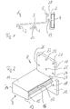
- the door sill 1 in Fig. 1 consists of a threshold part 2 and one water-repellent sheet metal part 3.
- the threshold part 2 has on its water-repellent sheet opposite side, d. H. the inside the door an insulation pad 4 and on the outside above the water-repellent sheet metal part 3 a groove 5, which acts as a guide for a Seal (not shown) is used.
- the water-repellent sheet metal part 3 has one on its underside Fastening device 6 and a support 7.
- a device 8 is used, which in Fig. 2 is shown.
- the device 8 consists essentially of a Body 9, which has an upper contact surface 10 for a frame, a first fastening device 11 for fastening the device 8 on the frame and a second fastening device 12 for Attach the threshold to the device.
- the body 9 is a substantially cuboid part with an upper one Contact surface 10, an underside 13 and two sides 14 and 15.
- the in installed position of the device facing outward side 14 of Body 9 is slightly higher than the inward-facing side 15, so that the body lying on the somewhat oblique water-repellent sheet metal part 3 has a horizontal upper bearing surface 10.
- the inside Pointing side 15 has an over the entire width of the side surface extending nose 16 which is in cross-section like one on a rib molded trapezoid is formed and in a corresponding groove 5 in the Threshold 1 can be inserted.
- the body also points to it upper contact surface 10 in the area of the inside 15 a right angle upward projecting contact surface 17, which side 15 upwards beyond the horizontal upper contact surface 10 of the body 9 extended.
- the upward-facing flange of the first fastening device 11 also has several holes 21 to 26 through the screws can be guided to the device 8 on any profile to attach a frame.
- An opening 27 in the flange of the first Fastening device 11 is arranged so that a tool through it can pass through to the stop surface 17 in the manufacture of Shaping device.
- the body 9 When using the device 8, the body 9 is first on the Shortened width of the metal spar and then the nose 16 of the body 9 in the Guide 5 of the threshold 1 inserted until the flanges 11 and 12 of the Place the device (8) on the front of the threshold 1. Subsequently is with screws that pass through the flange 12, the Device attached to the threshold by screws in the Screw channels 19 and 20 are screwed in.
- the blind spar of the outward opening door is placed so that the lower end face of the blind beam profile on the upper Support surface 10 of the body and the top 28 of the threshold 1 sits on.
- the abutment surface 17 can easily be reached with a chisel be removed so that the lower end face of the frame is full the top 28 of the threshold 1 and the bearing surface 10 of the body 9 rests.
- screw through the holes 21 are guided to 26, the frame attached to the flange 11 by the Screws are screwed into the profile of the frame.
Landscapes
- Engineering & Computer Science (AREA)
- Civil Engineering (AREA)
- Structural Engineering (AREA)
- Door And Window Frames Mounted To Openings (AREA)
- Specific Sealing Or Ventilating Devices For Doors And Windows (AREA)
- Body Structure For Vehicles (AREA)
- Joining Of Corner Units Of Frames Or Wings (AREA)
- Seal Device For Vehicle (AREA)
Description
- Fig. 1
- einen Schnitt durch das Profil einer Türschwelle und
- Fig. 2
- die Ansicht einer erfindungsgem. Vorrichtung zum Befestigen einer Türschwelle am Blendrahmen.
Claims (4)
- Vorrichtung (8) zum Befestigen einer Türschwelle (1) am Blendrahmen einer nach außen öffnenden Türe mit einem Körper (9), der eine obere Auflagefläche (10) für den Blendrahmen aufweist, einer ersten Befestigungseinrichtung (11) zum Befestigen der Vorrichtung (8) am Blendrahmen und einer zweiten Befestigungseinrichtung (12) zum Befestigen der Türschwelle (1) an der Vorrichtung (8), so daß die obere Auflagefläche (10) des Körpers (9) eine Ebene mit der Oberseite (28) der Türschwelle (1) bildet, dadurch gekennzeichnet, daß die Türschwelle (1) eine waagerechte Führung (5) für eine Dichtung aufweist und der Körper (9) eine Nase (16) mit einer Hinterschneidung, die in die Führung (5) einschiebbar ist.
- Vorrichtung nach Anspruch 1, dadurch gekennzeichnet, daß die Vorrichtung (8) mindestens einen Flansch (11,12) aufweist, um die Vorrichtung am Blendrahmen und/oder der Türschwelle (1) zu befestigen.
- Vorrichtung nach einem der vorhergehenden Ansprüche, dadurch gekennzeichnet , daß der Körper (9) in einem Teilbereich der oberen Auflagefläche (10) eine rechtwinklig nach oben vorstehende Anschlagfläche (17) aufweist, um das Positionieren des Blendrahmens zu erleichtern.
- Vorrichtung nach einem der vorhergehenden Ansprüche, dadurch gekennzeichnet, daß der Körper (9) zumindest teilweise hohl ist.
Applications Claiming Priority (2)
| Application Number | Priority Date | Filing Date | Title |
|---|---|---|---|
| DE19501483 | 1995-01-19 | ||
| DE19501483A DE19501483A1 (de) | 1995-01-19 | 1995-01-19 | Vorrichtung zum Befestigen einer Türschwelle am Blendrahmen einer nach außen öffnenden Türe |
Publications (2)
| Publication Number | Publication Date |
|---|---|
| EP0723063A1 EP0723063A1 (de) | 1996-07-24 |
| EP0723063B1 true EP0723063B1 (de) | 1998-02-18 |
Family
ID=7751831
Family Applications (1)
| Application Number | Title | Priority Date | Filing Date |
|---|---|---|---|
| EP95107145A Expired - Lifetime EP0723063B1 (de) | 1995-01-19 | 1995-05-11 | Vorrichtung zum Befestigen einer Türschwelle am Blendrahmen einer nach aussen öffnenden Türe |
Country Status (6)
| Country | Link |
|---|---|
| EP (1) | EP0723063B1 (de) |
| AT (1) | ATE163317T1 (de) |
| DE (2) | DE19501483A1 (de) |
| DK (1) | DK0723063T3 (de) |
| NL (1) | NL1001899C2 (de) |
| PL (1) | PL177860B1 (de) |
Families Citing this family (4)
| Publication number | Priority date | Publication date | Assignee | Title |
|---|---|---|---|---|
| DE19744240A1 (de) * | 1997-10-07 | 1999-04-08 | Peter Willrich | Türschwellenvorrichtung mit einer Türschwelle |
| DE10212229B4 (de) * | 2002-03-19 | 2011-04-14 | Profine Gmbh | Schwellenverbinder |
| US11072969B2 (en) | 2018-09-11 | 2021-07-27 | Endura Products, Llc | Door sill system, apparatus and methods for a door assembly |
| US11732525B2 (en) | 2021-02-02 | 2023-08-22 | Endura Products, Llc | Door sill system, apparatus, and methods for a door assembly |
Family Cites Families (5)
| Publication number | Priority date | Publication date | Assignee | Title |
|---|---|---|---|---|
| DE7046377U (de) * | 1971-03-18 | Fa Ludger Tumbrink | Seitenhalter fur die Befestigung einer Rohrschwelle | |
| AT379859B (de) * | 1982-03-09 | 1986-03-10 | Novoferm Stahlbauwerk Kg | Verbindungselement fuer eine bodenschiene an einer tuerzarge |
| DE8715664U1 (de) * | 1987-11-26 | 1988-02-04 | Niemann, Hans Dieter, 5014 Kerpen | Verbindungsteil eines Tür-, Fenster- od. dgl. Rahmens |
| DE8900207U1 (de) * | 1989-01-10 | 1989-03-02 | Niemann, Hans Dieter, 5014 Kerpen | Verbindungsteil eines Tür, Fenster- od.dgl. Rahmens |
| DE9420726U1 (de) * | 1994-12-24 | 1995-03-09 | MFT - Moderne Fenster Technik - GmbH, 26871 Papenburg | Schwellenhalter für Türrahmen zur Befestigung eines Rahmenprofiles an der Türschwelle |
-
1995
- 1995-01-19 DE DE19501483A patent/DE19501483A1/de not_active Withdrawn
- 1995-05-11 DE DE59501465T patent/DE59501465D1/de not_active Expired - Fee Related
- 1995-05-11 EP EP95107145A patent/EP0723063B1/de not_active Expired - Lifetime
- 1995-05-11 AT AT95107145T patent/ATE163317T1/de not_active IP Right Cessation
- 1995-05-11 DK DK95107145T patent/DK0723063T3/da active
- 1995-08-29 PL PL95310214A patent/PL177860B1/pl unknown
- 1995-12-14 NL NL1001899A patent/NL1001899C2/nl not_active IP Right Cessation
Also Published As
| Publication number | Publication date |
|---|---|
| DE19501483A1 (de) | 1996-07-25 |
| DE59501465D1 (de) | 1998-03-26 |
| ATE163317T1 (de) | 1998-03-15 |
| PL310214A1 (en) | 1996-07-22 |
| PL177860B1 (pl) | 2000-01-31 |
| NL1001899A1 (nl) | 1996-07-19 |
| NL1001899C2 (nl) | 1997-12-17 |
| EP0723063A1 (de) | 1996-07-24 |
| DK0723063T3 (da) | 1998-09-28 |
Similar Documents
| Publication | Publication Date | Title |
|---|---|---|
| DE69306761T2 (de) | Mechanismus für Glasschiebetüren | |
| DE2459017C3 (de) | Profilstreifen aus Kunststoff zum Einfassen und Befestigen einer Vorsatzscheibe an einem Fensterrahmen | |
| EP0723063B1 (de) | Vorrichtung zum Befestigen einer Türschwelle am Blendrahmen einer nach aussen öffnenden Türe | |
| DE102008015989B3 (de) | Schwellenhalter für Türrahmen | |
| DD139749A5 (de) | Eck-oder t-verbindung zweier profile | |
| DE2325970B2 (de) | Fensterrahmen | |
| DE2611323A1 (de) | Einstellvorrichtung | |
| EP0736660B1 (de) | Türschwelle | |
| EP0787880B1 (de) | Höhenverstelleinrichtung für einen unteren Abschluss von Türen oder Fenstern | |
| EP0674076B1 (de) | Verfahren und Vorrichtung zum Anbringen der Befestigungsbohrungen für Rahmen- und Flügelbandteile | |
| DE8717745U1 (de) | Vorrichtung zur einstellbaren Befestigung eines Scharnierbandes (Tür, Fenster) an einer Stahlzarge | |
| EP0445363A1 (de) | Fräs- oder Bohrvorrichtung | |
| EP0730074B1 (de) | Kantriegelbeschlag für Standflügel von doppelflügeligen Türen | |
| DE3145375C2 (de) | Mehrteiliges Rahmenprofil | |
| DE2810981C2 (de) | Vorrichtung zur Befestigung einer Zarge | |
| EP0736436B1 (de) | Schienenfahrzeug | |
| DE60318565T2 (de) | Fahrzeugdachkonstruktion und Dachreling für solch eine Dachkonstruktion | |
| DE9311188U1 (de) | Behälter, insbesondere Spülkasten mit einem daran befestigten Montageelement | |
| DE19944172B4 (de) | Rechteckfeld einer Rahmenfüllung | |
| DE19847316A1 (de) | Profilteil für Türschwellen und Türschwelle mit einer abfallend verlaufenden Oberseite | |
| DE69317511T2 (de) | Mechanismus zur Verbindung und Verriegelung einer Konsole eines Rolladens | |
| DE29819230U1 (de) | Tor | |
| DE102021129760A1 (de) | Verbindungsanordnung zum Verbinden eines Pfostens mit einem Rahmenprofil eines Fensters oder einer Türe aus Kunststoff | |
| DE3744729A1 (de) | Anschlagprofil fuer eine duschabtrennung | |
| DE9004985U1 (de) | Bodendichtungsleiste |
Legal Events
| Date | Code | Title | Description |
|---|---|---|---|
| PUAI | Public reference made under article 153(3) epc to a published international application that has entered the european phase |
Free format text: ORIGINAL CODE: 0009012 |
|
| AK | Designated contracting states |
Kind code of ref document: A1 Designated state(s): AT BE CH DE DK FR IT LI LU NL |
|
| 17P | Request for examination filed |
Effective date: 19961120 |
|
| 17Q | First examination report despatched |
Effective date: 19970313 |
|
| RAP1 | Party data changed (applicant data changed or rights of an application transferred) |
Owner name: WILLRICH, PETER |
|
| GRAG | Despatch of communication of intention to grant |
Free format text: ORIGINAL CODE: EPIDOS AGRA |
|
| GRAG | Despatch of communication of intention to grant |
Free format text: ORIGINAL CODE: EPIDOS AGRA |
|
| GRAH | Despatch of communication of intention to grant a patent |
Free format text: ORIGINAL CODE: EPIDOS IGRA |
|
| GRAH | Despatch of communication of intention to grant a patent |
Free format text: ORIGINAL CODE: EPIDOS IGRA |
|
| GRAA | (expected) grant |
Free format text: ORIGINAL CODE: 0009210 |
|
| AK | Designated contracting states |
Kind code of ref document: B1 Designated state(s): AT BE CH DE DK FR IT LI LU NL |
|
| PG25 | Lapsed in a contracting state [announced via postgrant information from national office to epo] |
Ref country code: NL Free format text: LAPSE BECAUSE OF FAILURE TO SUBMIT A TRANSLATION OF THE DESCRIPTION OR TO PAY THE FEE WITHIN THE PRESCRIBED TIME-LIMIT Effective date: 19980218 |
|
| REF | Corresponds to: |
Ref document number: 163317 Country of ref document: AT Date of ref document: 19980315 Kind code of ref document: T |
|
| ITF | It: translation for a ep patent filed | ||
| REG | Reference to a national code |
Ref country code: CH Ref legal event code: NV Representative=s name: DIPL.-ING. ETH H. R. WERFFELI PATENTANWALT Ref country code: CH Ref legal event code: EP |
|
| ET | Fr: translation filed | ||
| REF | Corresponds to: |
Ref document number: 59501465 Country of ref document: DE Date of ref document: 19980326 |
|
| NLV1 | Nl: lapsed or annulled due to failure to fulfill the requirements of art. 29p and 29m of the patents act | ||
| REG | Reference to a national code |
Ref country code: DK Ref legal event code: T3 |
|
| PLBE | No opposition filed within time limit |
Free format text: ORIGINAL CODE: 0009261 |
|
| STAA | Information on the status of an ep patent application or granted ep patent |
Free format text: STATUS: NO OPPOSITION FILED WITHIN TIME LIMIT |
|
| 26N | No opposition filed | ||
| PGFP | Annual fee paid to national office [announced via postgrant information from national office to epo] |
Ref country code: FR Payment date: 19990518 Year of fee payment: 5 |
|
| PGFP | Annual fee paid to national office [announced via postgrant information from national office to epo] |
Ref country code: LU Payment date: 19990520 Year of fee payment: 5 |
|
| PGFP | Annual fee paid to national office [announced via postgrant information from national office to epo] |
Ref country code: DK Payment date: 19990526 Year of fee payment: 5 Ref country code: BE Payment date: 19990526 Year of fee payment: 5 Ref country code: AT Payment date: 19990526 Year of fee payment: 5 |
|
| PGFP | Annual fee paid to national office [announced via postgrant information from national office to epo] |
Ref country code: CH Payment date: 19990616 Year of fee payment: 5 |
|
| PG25 | Lapsed in a contracting state [announced via postgrant information from national office to epo] |
Ref country code: LU Free format text: LAPSE BECAUSE OF NON-PAYMENT OF DUE FEES Effective date: 20000511 Ref country code: DK Free format text: LAPSE BECAUSE OF NON-PAYMENT OF DUE FEES Effective date: 20000511 Ref country code: AT Free format text: LAPSE BECAUSE OF NON-PAYMENT OF DUE FEES Effective date: 20000511 |
|
| PG25 | Lapsed in a contracting state [announced via postgrant information from national office to epo] |
Ref country code: LI Free format text: LAPSE BECAUSE OF NON-PAYMENT OF DUE FEES Effective date: 20000531 Ref country code: CH Free format text: LAPSE BECAUSE OF NON-PAYMENT OF DUE FEES Effective date: 20000531 Ref country code: BE Free format text: LAPSE BECAUSE OF NON-PAYMENT OF DUE FEES Effective date: 20000531 |
|
| BERE | Be: lapsed |
Owner name: WILLRICH PETER Effective date: 20000531 |
|
| REG | Reference to a national code |
Ref country code: CH Ref legal event code: PL |
|
| REG | Reference to a national code |
Ref country code: DK Ref legal event code: EBP |
|
| PG25 | Lapsed in a contracting state [announced via postgrant information from national office to epo] |
Ref country code: FR Free format text: LAPSE BECAUSE OF NON-PAYMENT OF DUE FEES Effective date: 20010131 |
|
| REG | Reference to a national code |
Ref country code: FR Ref legal event code: ST |
|
| PG25 | Lapsed in a contracting state [announced via postgrant information from national office to epo] |
Ref country code: IT Free format text: LAPSE BECAUSE OF NON-PAYMENT OF DUE FEES;WARNING: LAPSES OF ITALIAN PATENTS WITH EFFECTIVE DATE BEFORE 2007 MAY HAVE OCCURRED AT ANY TIME BEFORE 2007. THE CORRECT EFFECTIVE DATE MAY BE DIFFERENT FROM THE ONE RECORDED. Effective date: 20050511 |
|
| PGFP | Annual fee paid to national office [announced via postgrant information from national office to epo] |
Ref country code: DE Payment date: 20080523 Year of fee payment: 14 |
|
| PG25 | Lapsed in a contracting state [announced via postgrant information from national office to epo] |
Ref country code: DE Free format text: LAPSE BECAUSE OF NON-PAYMENT OF DUE FEES Effective date: 20091201 |