EP0723154A2 - Flammenionisationsdetektor mit Flammenspitze auf dem Diffusor - Google Patents
Flammenionisationsdetektor mit Flammenspitze auf dem Diffusor Download PDFInfo
- Publication number
- EP0723154A2 EP0723154A2 EP96100415A EP96100415A EP0723154A2 EP 0723154 A2 EP0723154 A2 EP 0723154A2 EP 96100415 A EP96100415 A EP 96100415A EP 96100415 A EP96100415 A EP 96100415A EP 0723154 A2 EP0723154 A2 EP 0723154A2
- Authority
- EP
- European Patent Office
- Prior art keywords
- diffuser
- detector
- tube
- flame
- gas
- Prior art date
- Legal status (The legal status is an assumption and is not a legal conclusion. Google has not performed a legal analysis and makes no representation as to the accuracy of the status listed.)
- Withdrawn
Links
- 230000005684 electric field Effects 0.000 claims abstract description 14
- 239000007800 oxidant agent Substances 0.000 claims abstract description 13
- 230000001590 oxidative effect Effects 0.000 claims abstract description 13
- XUIMIQQOPSSXEZ-UHFFFAOYSA-N Silicon Chemical compound [Si] XUIMIQQOPSSXEZ-UHFFFAOYSA-N 0.000 claims abstract description 9
- 229910052710 silicon Inorganic materials 0.000 claims abstract description 9
- 239000010703 silicon Substances 0.000 claims abstract description 9
- 239000000446 fuel Substances 0.000 claims abstract description 8
- 238000000034 method Methods 0.000 claims description 10
- 238000002485 combustion reaction Methods 0.000 claims description 9
- VYPSYNLAJGMNEJ-UHFFFAOYSA-N Silicium dioxide Chemical compound O=[Si]=O VYPSYNLAJGMNEJ-UHFFFAOYSA-N 0.000 claims description 6
- 239000005350 fused silica glass Substances 0.000 claims description 6
- 238000004519 manufacturing process Methods 0.000 claims description 4
- 238000005530 etching Methods 0.000 claims description 3
- 239000012212 insulator Substances 0.000 claims description 2
- 239000011148 porous material Substances 0.000 claims description 2
- 239000012530 fluid Substances 0.000 claims 1
- 239000007789 gas Substances 0.000 description 25
- 229910052751 metal Inorganic materials 0.000 description 16
- 239000002184 metal Substances 0.000 description 16
- UFHFLCQGNIYNRP-UHFFFAOYSA-N Hydrogen Chemical compound [H][H] UFHFLCQGNIYNRP-UHFFFAOYSA-N 0.000 description 14
- 239000001257 hydrogen Substances 0.000 description 14
- 229910052739 hydrogen Inorganic materials 0.000 description 14
- 239000000919 ceramic Substances 0.000 description 13
- 150000002500 ions Chemical class 0.000 description 12
- 239000000523 sample Substances 0.000 description 11
- 239000000853 adhesive Substances 0.000 description 5
- 230000001070 adhesive effect Effects 0.000 description 5
- 229910052782 aluminium Inorganic materials 0.000 description 5
- XAGFODPZIPBFFR-UHFFFAOYSA-N aluminium Chemical compound [Al] XAGFODPZIPBFFR-UHFFFAOYSA-N 0.000 description 5
- OFBQJSOFQDEBGM-UHFFFAOYSA-N n-pentane Natural products CCCCC OFBQJSOFQDEBGM-UHFFFAOYSA-N 0.000 description 5
- 238000005253 cladding Methods 0.000 description 4
- 238000009792 diffusion process Methods 0.000 description 4
- 239000000758 substrate Substances 0.000 description 4
- 239000012491 analyte Substances 0.000 description 3
- 238000005513 bias potential Methods 0.000 description 3
- 239000001273 butane Substances 0.000 description 3
- 239000000463 material Substances 0.000 description 3
- 238000005459 micromachining Methods 0.000 description 3
- IJDNQMDRQITEOD-UHFFFAOYSA-N n-butane Chemical compound CCCC IJDNQMDRQITEOD-UHFFFAOYSA-N 0.000 description 3
- 150000002894 organic compounds Chemical class 0.000 description 3
- ATUOYWHBWRKTHZ-UHFFFAOYSA-N Propane Chemical compound CCC ATUOYWHBWRKTHZ-UHFFFAOYSA-N 0.000 description 2
- QVGXLLKOCUKJST-UHFFFAOYSA-N atomic oxygen Chemical compound [O] QVGXLLKOCUKJST-UHFFFAOYSA-N 0.000 description 2
- 238000004587 chromatography analysis Methods 0.000 description 2
- 239000004020 conductor Substances 0.000 description 2
- 238000001514 detection method Methods 0.000 description 2
- 238000004817 gas chromatography Methods 0.000 description 2
- 229930195733 hydrocarbon Natural products 0.000 description 2
- 150000002430 hydrocarbons Chemical class 0.000 description 2
- 239000000203 mixture Substances 0.000 description 2
- 239000001301 oxygen Substances 0.000 description 2
- 229910052760 oxygen Inorganic materials 0.000 description 2
- 230000004044 response Effects 0.000 description 2
- 230000035945 sensitivity Effects 0.000 description 2
- 229910001220 stainless steel Inorganic materials 0.000 description 2
- 239000010935 stainless steel Substances 0.000 description 2
- 239000004215 Carbon black (E152) Substances 0.000 description 1
- 229910001111 Fine metal Inorganic materials 0.000 description 1
- 239000004642 Polyimide Substances 0.000 description 1
- 239000004809 Teflon Substances 0.000 description 1
- 229920006362 Teflon® Polymers 0.000 description 1
- 230000008901 benefit Effects 0.000 description 1
- 238000007599 discharging Methods 0.000 description 1
- 238000002124 flame ionisation detection Methods 0.000 description 1
- 239000011521 glass Substances 0.000 description 1
- 238000002347 injection Methods 0.000 description 1
- 239000007924 injection Substances 0.000 description 1
- 238000012986 modification Methods 0.000 description 1
- 230000004048 modification Effects 0.000 description 1
- 239000000615 nonconductor Substances 0.000 description 1
- 229920002120 photoresistant polymer Polymers 0.000 description 1
- 229920001721 polyimide Polymers 0.000 description 1
- 230000008569 process Effects 0.000 description 1
- 239000001294 propane Substances 0.000 description 1
- 230000009467 reduction Effects 0.000 description 1
- 230000001105 regulatory effect Effects 0.000 description 1
- 230000000284 resting effect Effects 0.000 description 1
- 238000000926 separation method Methods 0.000 description 1
Images

Classifications
-
- G—PHYSICS
- G01—MEASURING; TESTING
- G01N—INVESTIGATING OR ANALYSING MATERIALS BY DETERMINING THEIR CHEMICAL OR PHYSICAL PROPERTIES
- G01N30/00—Investigating or analysing materials by separation into components using adsorption, absorption or similar phenomena or using ion-exchange, e.g. chromatography or field flow fractionation
- G01N30/02—Column chromatography
- G01N30/62—Detectors specially adapted therefor
- G01N30/64—Electrical detectors
- G01N30/68—Flame ionisation detectors
-
- G—PHYSICS
- G01—MEASURING; TESTING
- G01N—INVESTIGATING OR ANALYSING MATERIALS BY DETERMINING THEIR CHEMICAL OR PHYSICAL PROPERTIES
- G01N30/00—Investigating or analysing materials by separation into components using adsorption, absorption or similar phenomena or using ion-exchange, e.g. chromatography or field flow fractionation
- G01N2030/0095—Separation specially adapted for use outside laboratory, e.g. field sampling, portable equipments
-
- G—PHYSICS
- G01—MEASURING; TESTING
- G01N—INVESTIGATING OR ANALYSING MATERIALS BY DETERMINING THEIR CHEMICAL OR PHYSICAL PROPERTIES
- G01N30/00—Investigating or analysing materials by separation into components using adsorption, absorption or similar phenomena or using ion-exchange, e.g. chromatography or field flow fractionation
- G01N30/02—Column chromatography
- G01N2030/022—Column chromatography characterised by the kind of separation mechanism
- G01N2030/025—Gas chromatography
Definitions
- This invention relates to flame ionization detectors for e.g. gas chromatography and more particularly to such detectors of compact size and low fuel requirement.
- FID flame ionization detector
- the effluent gas (sample) from the analytical column of a gas chromatograph is premixed with hydrogen makeup gas and burned at the top of a flame tip with air (or oxygen) as oxidant. The burning decomposes the organic analytes and ionizes them quantitatively.
- the resulting ions or electrons are collected by a cylindrical electrode located adjacent the flame tip. Another electrode located below the flame tip provides a bias potential, so that an electrical field develops between the two electrodes. Current flowing between the two electrodes is proportional to the number of ions or electrons produced and collected.
- a diffusion flame is the most efficient way to ionize the analyte (sample).
- the introduction of air must also be done very smoothly to minimize flicker noise, caused by having a flame burning unsteadily, and typically resulting from an air inlet that does not bring the air to the flame tip smoothly. It is known (see Modern Practice of Gas Chromatagraphy , ed. Robert L. Grob, 1985, p. 244) to introduce the air through a porous diffuser located well below the tip of the jet. Flicker noise is also reduced in the prior art by allowing sufficient vertical distance between the air inlet and the flame tip so as to develop a laminar air flow, however a sufficient vertical distance undesirably results in a physically longer detector.
- a prior art flame ionization detector shown in Figure 1 includes signal probe 10, igniter probe 12, flame tip assembly 14, spring clip 16 (which is the first electrode), igniter coil 18, insulator 20, and a collector tube (second electrode) 22. (No air diffuser is present in this detector).
- the flame is created by burning hydrogen plus the analyte in air or oxygen.
- a bias potential of up to 300V is maintained between spring clip 16 and collector tube 22. Ions or electrons formed during the combustion process are collected by collector tube 22 and result in the flow of a small electrical current, which is measured by an external circuit.
- the hydrogen flame by itself produces very few ions or electrons, i.e. very low electrical current, but when an organic compound (e.g.
- a hydrocarbon is present in the gas stream in the form of a gas chromatograph peak, large quantities of ions and electrons proportional to the number of organic molecules are created.
- ions and electrons are formed.
- the bias electrode the spring clip of Figure 1
- the collector tube is positive
- electrons will be collected.
- the bias electrode is positive and the collector tube is negative or grounded
- ions are collected. Ions are usually easier to collect because of their larger size.
- An elevated current is produced and can be recorded (observed) by an external circuit. A recording of the current versus time reproduces the mass of organic compounds in the gas chromatograph peak.
- the prior art detector of Figure 1 is disadvantageously large, typically having a height H of about 5 to 7 cm. This is because a large distance must be allowed to smooth the inlet air flow in order to reduce the flicker noise caused by the air flow turbulence.
- the distance h, which is from the air inlet to the top of the flame tip, for this prior art detector is about 2 to 2.5 cms.
- the flame ionization detector of Figure 1 is assembled from a number of individually fabricated metal and ceramic components each of which is relatively large.
- Collector tube 22 is an example. Its height is greater than h, the distance between air inlet and top of flame tip. Probes 10 and 12 are also bulky, resulting in an undesirably large horizontal dimension. The large size of this flame ionization detector makes it difficult to use in portable applications.
- Flame tip inside diameters used in prior art detectors range from 0.010 to 0.020" (0.254 to 0.508mm).
- a larger flame tip requires a larger hydrogen flow to maintain an efficient ionization flame. This produces a larger flame in terms of height and radius and requires a larger collector, thus increasing the size of the detector.
- a smaller flow of hydrogen must be used and its use reduces the size of the collector and subsequently the size of the detector in addition to the advantage of having better gas economy and ease of operation (due to not needing to recharge gas cylinders so frequently).
- a flame ionization detector has a very efficient diffusion flame, and requires only a low hydrogen make-up gas and air flow. Typical flow rates are 12 ml/min for hydrogen make-up gas and 120 ml/min of air. The detector response is fast, its size is small and flicker noise is minimized without needing a significant vertical distance between the air inlet and the flame tip. While the background noise of conventional flame ionization detectors is reported to be on the order of a few picoamperes, the present invention can achieve a background noise of a small fraction of a picoampere (e.g. ⁇ 0.2 pA) even under a high electrical field strength of e.g. 220V/mm. (See "The flame ionization detector” in Detectors for Capillary Chromatography edited by H.H. Hill and D.G. McMinn, Wiley InterScience Pub., New York, 1992, page 14.)
- a flame ionization detector in accordance with the present invention includes a small inside diameter tube for carrying the sample from the column of the gas chromatograph together with the hydrogen makeup gas.
- This small I.D. tube passes through a hole in a diffuser plate which includes a large number of very small and precisely formed diffuser "microchannels" formed through it.
- the tube terminates immediately above the upper surface of the diffuser plate, thus locating the flame tip as close as possible to the upper surface of the diffuser plate.
- the air (or other oxidant) needed for combustion is introduced from beneath the diffuser plate flowing in a direction parallel to the plane defined by the diffuser plate (perpendicular to the diffuser microchannels) and flows through the diffuser microchannels to support the combustion at the flame tip assembly.
- the diffuser plate and the direction of air flow to the diffuser plate thereby minimize turbulence in the air flow when the air reaches the flame tip, eliminating flame flicker noise.
- the diffuser plate may be a porous metal plate, an etched silicon plate, or other similar structure.
- This diffuser plate which advantageously is located very near the flame tip, allows the air to be introduced immediately adjacent the flame tip, thus eliminating the need for a substantial vertical separation between the air inlet and the flame tip.
- This structure reduces overall detector height, allowing a more compact (portable) device.
- a typical distance from the flame tip to the upper surface of the diffuser plate is 1 to 2 mm.
- the flame tip is located at the lower end of a 4 to 6 mm height collector.
- the collector has an I.D. of about 4.5. mm to achieve high electrical field strength for efficient collection. This close spacing advantageously minimizes the internal volume of the detector.
- the overall height of the detector assembly may advantageously be less than 1.5 centimeter. The overall compactness also conserves electrical power to heat the detector to operating temperatures.
- the flicker noise minimization due to turbulence reduction results in a higher signal to noise ratio and lowers the detection limit of the detector.
- the present device is very sensitive, and can detect a small quantity of hydrocarbons. While a typical FID is reported to respond to 20 pg of a component from a high resolution capillary column (See “Flame Ionization Detector” by Dennis G. McMinn and Herbert H. Hill, IN “Detectors for Capillary Chromatography", edited by Herbert H. Hill and Dennis G. McMinn, 1992, pg. 16.), the present device, under general operating conditions, can detect down to 0.5 pg of butane in a 500 msec fast peak.
- Optimizing the injection volume, gas flows and operating temperature can lower the detection limit to at least 0.25 pg of butane.
- the present device is one to two orders more sensitive than in the prior art.
- the present device can analyze very small sample volumes, down to 3.5 ⁇ l.
- the diffuser plate in one version is fabricated by micromachining a silicon wafer, by etching the diffusion microchannels through the plate and also micromachining the wafer so that a thinner central portion of the plate (which includes the diffusion microchannels) is surrounded by a thicker rim for mechanical strength.
- the diffuser plate is a commercially available porous metal plate.
- the gas carrying tube in one version is metal clad fused silica. This metal cladding is one electrode, the second electrode being a conductive metal cylinder located above the flame tip area.
- the flame ignition device is in one version a high voltage sparking (discharging) needle or pin resting horizontally on the top of a ceramic structure enclosing the collector. Sparking occurs when the voltage is about 1500V and ignites the hydrogen/air mixture.
- the sparking gap needle or pin pointed metal conductor
- Ignition may also be by means of a hot wire. The sparking gap is easier to install and operate than the hot wire. There is no need to control the electrical current with the sparking gap.
- a high electrical field strength is used for detecting low concentrations of sample.
- This field strength is over 150V/mm and preferably in the range of 220 to 250V/mm to maximize the signal to noise ratio.
- the small physical size allows provision of such a strong electric field with fairly modest voltages (700 to 800V).
- the physically much larger prior art FIDs would require dangerously high voltages to provide such a strong electric field.
- Figure 1 shows a prior art flame ionization detector.
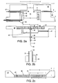
- Figure 2a shows a flame ionization detector in accordance with the present invention.
- FIGS 2b and 2c show detail of the apparatus of Figure 2a.
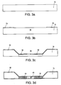
- Figures 3a to 3d show fabrication of a micromachine diffuser plate in accordance with the present invention.
- FIG. 2a shows in cross section a flame ionization detector (FID) in accordance with the present invention.
- the flame tip 32 is the end of a length of aluminum clad fused silica capillary tube 31.
- the tube 31 I.D. is e.g. 100, 175 or 220 micrometers ( ⁇ m). (These and other dimensions and materials herein are exemplary and not limiting.)
- the aluminum cladding 33 (see Figure 2b) is 20 to 40 micrometers thick. Other metal cladding may be used or other metal may be combined with the aluminum.
- Such clad tubing is commercially available from Scientific Glass Engineering, part nos. 060-220, 060-175 and 060-100.
- the surface of fused silica is known to provide high inertness and purity for the passage of gas chromatograph analytes. Fused silica is also extremely refractory.
- a high bias voltage potential is provided to the aluminum cladding 33 which is the first electrode of the flame ionization detector so that the electrical field strength is e.g. up to 250 V/mm.
- the gas sample 60 (shown schematically in Figure 2a), provided from the column of a conventional gas chromatograph, is conventionally premixed with make-up hydrogen (not shown) and directed to the other end of tube 31.
- the aluminum clad fused silica tube 31 is fixed and insulated in a ceramic tube 34. Only about 1 mm of tube 31 is exposed and that is the flame tip 32.
- the upper end of ceramic tube 34 is bonded with a high temperature and electrically non-conductive adhesive 35 to extend about 500 micrometers from the central hole 36 (which is about 850 micrometers in diameter) of diffuser plate 37.
- the electrode bias voltage is provided by a conventional high voltage circuit that includes a standard 12V DC primary supply that powers a high voltage power supply providing up to 1500V for both ignition and electrode biasing.
- the high voltage power supply of the type commercially available is stable with low ripple.
- a regulatory circuit may be added to maintain a stable primary supply voltage.
- a switch connects the high voltage supply to alternatively the ignition circuit or the first FID electrode; the second electrode is held at ground. Other sources of high voltage may be used alternatively.
- Ceramic is an extremely good electrical insulator and insulates the first electrode 33 (at the bias potential) from the rest of the structure.
- Diffuser plate 37 is bonded to a metal base plate 38 by a high temperature adhesive.
- Tube 31 and ceramic sheath tube 34 are also bonded by adhesive 35 to base plate 38 at central hole 39 which is 850 micrometers in diameter.
- Base plate 38 defines a central cavity 40.
- Base plate 38 also defines a horizontal channel 41 which communicates with cavity 40.
- Channel 41 is 860 micrometers in diameter.
- a stainless steel air tube with a diameter of 800 micrometers (not shown) is connected to the outside end of channel 40 by means of a high temperature adhesive.
- Channel 41 provides air or other oxidant to the detector.
- Diffuser plate 37 can be a precisely pored disk as provided by Mott Metallurgical Corporation (Part No. 1000-.500-.039-2 or 1000-.375-.039-2). These stainless steel disks have 2 micrometer diameter pores.
- Diffuser plate 37 (which can also be formed by silicon micromachining as described below) has central cavity 42. Detail of diffuser plate 37 is shown in Figure 2c. Many tiny microchannels 43 in the central portion 44 of diffuser plate 37 diffuse the air from channel 41 to the combustion compartment 51. There are no diffuser holes in the very central portion 44 of diffuser plate 37; this is intended to minimize flame flickering caused by direct impact of the incoming air flow on the flame.
- Base plate 38 is fastened by screws to top metal plate 50. Fastening can also be done by a high temperature adhesive.
- Metal plate 50 defines a large cylindrical bore in its center. The lower portion of the bore is larger and is the combustion chamber 51.
- a ceramic sheath 52 is inserted into combustion chamber 51 and metal cylinder 53 is inserted into the ceramic sheath 52.
- Metal cylinder 53 is the second electrode (collector) of the detector. Ceramic sheath 52 insulates this second electrode 53 from the rest of the structure.
- a polyimide, teflon or ceramic insulated conductor wire 54 is passed through a lateral predrilled channel 55 at the bottom of plate 50. Wire 54 contacts electrode 53 and is a signal lead. This signal lead 54 is conventionally connected to an external current measuring circuit (not shown).
- a ceramic sheathed fine metal pin 56 is passed into the top portion of combustion chamber 51 through another lateral predrilled channel 57. Metal pin 56 discharges and sparks when the applied voltage is about 1500V. The spark then ignites the flame.
- Another lateral channel 58 holds a temperature sensor 59.
- the external and internal diameter of the collector in one embodiment are 6.4 and 4.5 mm, respectively.
- a very small flame allows the use of a small collector, and a small collector reduces the overall size of the FID.
- the flame tip is located 1-2 mm (less than 5mm) above the diffuser surface.
- a "turbulence buffer” like passage zone (chamber 40) is created.
- a very smooth flow of air out to the flame tip is achieved, minimizing the flicker noise.
- the collector 53 is a cylinder only about 5 mm long. With its ceramic sheath 52, it is about 6 mm long.
- the high voltage discharge pin 56 is therefore only 6 mm away from the flame tip (source of fuel) and can easily ignite the gas mixture. Most of the discharge pin 56 (except the tip) is protected by the ceramic sheath 52 insulating the collector cylinder 53. This protection plus pin 56 being spaced away from the axial flow of the burning product minimizes residue deposit on the pin 56 surface.
- the FID in use is assembled to form a unitary structure.
- the overall (vertical) height of the device in this exemplary embodiment is less than 1.50 centimeters.
- each of the microchannels in the micromachined embodiment 43 is also approximately 2 micrometers and there are approximately 17,000 microchannels provided with a center-to-center spacing of approximately 45 micrometers.
- the particular layout of the microchannels is not believed to be critical.
- the thickness of the central portion of the diffuser plate 37 which contains the microchannels 43 is approximately 50 micrometers, although this dimension is also not critical.
- a typical gas flow 60 is about 12 ml/min, of which approximately 1-2 ml/min is the carrier flow containing the analyte and the remainder is the hydrogen makeup gas.
- Optimum fuel/flow is about 15 ml/min for a flame tip with an inside diameter of 175 ⁇ m. This gives high sensitivity. To save fuel, the fuel flow can be reduced to 10 ml/min.
- the air flow stream through channel 41 is approximately 10 times the flow 60, as is conventional. Higher air flow increases sensitivity slightly.
- the present invention uses a very high electrical field strength (e.g. up to 250V/mm) to collect the ions.
- a very high electrical field strength e.g. up to 250V/mm
- the FID there is an increased signal to noise ratio when the field strength is increased.
- the increase has been found to be extraordinary when the field strength is over 150V/mm.
- detector noise is also magnified.
- An optimum range of about 220-250 V/mm has been found where the gain of signal to noise ratio is the maximum.
- No known prior art uses such a high electrical field to collect ions or electrons. Theoretically, ions are being multiplied and so a stronger signal is produced. Good linearity of the response under this bias voltage is maintained from 30 ppb to at least 10,000 ppm of sample concentration where e.g. the sample contains propane, butane and pentane.
- Figures 3a through 3d show fabrication by silicon processing techniques of a silicon diffuser plate in accordance with one embodiment of the invention.
- Figure 3a begins with a conventional silicon wafer 76 (substrate) of 300 micrometer thickness. It is to be understood that these figures show only a portion of the wafer and that a number of such diffuser plates (each having a size of about 1 cm by 1 cm) would be formed simultaneously in one wafer and then the individual diffuser plates are conventionally scribed and separated into individual components.
- a central portion 78 of substrate 76 is conventionally exposed by a patterned photoresist mask layer 79 and etched using an anisotropic etch defining cavity 78 in Fig. 3c.
- Mask layer 79 is then stripped.
- the surface of substrate 76 is masked by mask layer 81, a portion 82 of which defines a large number of small exposed areas (the diffuser channels).
- an anisotropic etching step using the mask layer 81, etches a number of very small micro channels 84 and a central hole 85 extending through substrate 76.
- This second mask layer 81 (including portions 82 thereof) is then stripped.
- the surface of the structure shown in Figure 3d may then be coated by a metal layer 90.
- Each diffuser plate is then, as described above, scribed from the wafer.
- the diffuser plate is then assembled with the other components as shown in Figure 2a. Fabrication of all other components is conventional.
Landscapes
- Physics & Mathematics (AREA)
- Health & Medical Sciences (AREA)
- Life Sciences & Earth Sciences (AREA)
- Chemical & Material Sciences (AREA)
- Analytical Chemistry (AREA)
- Biochemistry (AREA)
- General Health & Medical Sciences (AREA)
- General Physics & Mathematics (AREA)
- Immunology (AREA)
- Pathology (AREA)
- Other Investigation Or Analysis Of Materials By Electrical Means (AREA)
Applications Claiming Priority (2)
| Application Number | Priority Date | Filing Date | Title |
|---|---|---|---|
| US375330 | 1995-01-17 | ||
| US08/375,330 US5576626A (en) | 1995-01-17 | 1995-01-17 | Compact and low fuel consumption flame ionization detector with flame tip on diffuser |
Publications (2)
| Publication Number | Publication Date |
|---|---|
| EP0723154A2 true EP0723154A2 (de) | 1996-07-24 |
| EP0723154A3 EP0723154A3 (de) | 1998-04-15 |
Family
ID=23480465
Family Applications (1)
| Application Number | Title | Priority Date | Filing Date |
|---|---|---|---|
| EP96100415A Withdrawn EP0723154A3 (de) | 1995-01-17 | 1996-01-12 | Flammenionisationsdetektor mit Flammenspitze auf dem Diffusor |
Country Status (4)
| Country | Link |
|---|---|
| US (1) | US5576626A (de) |
| EP (1) | EP0723154A3 (de) |
| JP (1) | JPH08254525A (de) |
| DE (1) | DE723154T1 (de) |
Cited By (1)
| Publication number | Priority date | Publication date | Assignee | Title |
|---|---|---|---|---|
| EP0922956A1 (de) * | 1997-12-13 | 1999-06-16 | Pierburg Aktiengesellschaft | Flammenionisationsdetektor |
Families Citing this family (10)
| Publication number | Priority date | Publication date | Assignee | Title |
|---|---|---|---|---|
| EP0861402A1 (de) * | 1995-11-13 | 1998-09-02 | Gas Research Institute | Flammenionisationsgeregelte brennereinrichtung und -verfahren |
| US6238622B1 (en) * | 1997-12-05 | 2001-05-29 | Rosemount Analytical Inc. | Flame ionization detector |
| US6132552A (en) | 1998-02-19 | 2000-10-17 | Micron Technology, Inc. | Method and apparatus for controlling the temperature of a gas distribution plate in a process reactor |
| US6299433B1 (en) | 1999-11-05 | 2001-10-09 | Gas Research Institute | Burner control |
| US6701774B2 (en) | 2000-08-02 | 2004-03-09 | Symyx Technologies, Inc. | Parallel gas chromatograph with microdetector array |
| US7241135B2 (en) * | 2004-11-18 | 2007-07-10 | Honeywell International Inc. | Feedback control for modulating gas burner |
| JP2006343313A (ja) * | 2005-05-13 | 2006-12-21 | Horiba Ltd | 水素炎を利用した可搬型測定装置 |
| EP2037264A1 (de) * | 2007-09-13 | 2009-03-18 | Technische Universität Hamburg-Harburg | Flammenionisationsdetektor |
| CN101981441B (zh) * | 2008-03-25 | 2013-03-13 | 国立大学法人大阪大学 | 放电电离电流检测器 |
| WO2011106747A1 (en) * | 2010-02-26 | 2011-09-01 | Perkin Elmer Health Sciences, Inc. | Jet assembly for use in detectors and other devices |
Family Cites Families (8)
| Publication number | Priority date | Publication date | Assignee | Title |
|---|---|---|---|---|
| NL6711839A (de) * | 1966-10-01 | 1968-04-02 | ||
| US3542516A (en) * | 1968-10-09 | 1970-11-24 | Phillips Petroleum Co | Flame ionization detection |
| US3905755A (en) * | 1974-01-21 | 1975-09-16 | Leonard E Aske | Miniature blowtorch |
| US4182740A (en) * | 1976-03-01 | 1980-01-08 | Varian Associates, Inc. | Flame ionization detector |
| FR2430009A1 (fr) * | 1978-06-26 | 1980-01-25 | Inst Francais Du Petrole | Detecteur a flamme ionisante pouvant fonctionner a temperature elevee |
| SU783676A1 (ru) * | 1978-12-18 | 1980-11-30 | Всесоюзный Научно-Исследовательский И Проектно-Конструкторский Институт Комплексной Автоматизации Нефтяной И Газовой Промышленности | Способ ионизационно-пламенного детектировани в газовой хроматографии |
| US5073753A (en) * | 1987-08-03 | 1991-12-17 | Cambustion, Limited | Hydrocarbon flame ionization detector |
| KR950004615B1 (ko) * | 1990-09-27 | 1995-05-03 | 미쓰비시덴키 가부시키가이샤 | 내연기관용 점화플러그 |
-
1995
- 1995-01-17 US US08/375,330 patent/US5576626A/en not_active Expired - Fee Related
-
1996
- 1996-01-12 EP EP96100415A patent/EP0723154A3/de not_active Withdrawn
- 1996-01-12 DE DE0723154T patent/DE723154T1/de active Pending
- 1996-01-16 JP JP8023309A patent/JPH08254525A/ja active Pending
Cited By (2)
| Publication number | Priority date | Publication date | Assignee | Title |
|---|---|---|---|---|
| EP0922956A1 (de) * | 1997-12-13 | 1999-06-16 | Pierburg Aktiengesellschaft | Flammenionisationsdetektor |
| US5969617A (en) * | 1997-12-13 | 1999-10-19 | Pierburg Ag | Flame ionization detector |
Also Published As
| Publication number | Publication date |
|---|---|
| US5576626A (en) | 1996-11-19 |
| JPH08254525A (ja) | 1996-10-01 |
| DE723154T1 (de) | 1997-09-25 |
| EP0723154A3 (de) | 1998-04-15 |
Similar Documents
| Publication | Publication Date | Title |
|---|---|---|
| US5576626A (en) | Compact and low fuel consumption flame ionization detector with flame tip on diffuser | |
| US5889404A (en) | Discharge ionization detector having efficient transfer of metastables for ionization of sample molecules | |
| US4182740A (en) | Flame ionization detector | |
| EP0262223B1 (de) | Detektor für gaschromatographen | |
| CA1331293C (en) | High temperature flame jet for gas chromatography | |
| WO1989001149A1 (en) | Hydrocarbon flame ionization detector | |
| US10048222B2 (en) | Miniaturized helium photoionization detector | |
| JP2953590B2 (ja) | 放電イオン化検知器 | |
| US6457347B1 (en) | Glow discharge detector | |
| EP0286757B1 (de) | Chromatographischer Dünnschicht-Flammionisationsdetektor für die mengenmässige Analyse von chromatographisch getrennten Substanzen | |
| EP1279955B2 (de) | Heliumionisierungsdetektor | |
| EP1018647A2 (de) | Mikrogas Detektor | |
| US6156103A (en) | Discharge gas purification system | |
| US6107805A (en) | Extended detection zone in an ionization detector | |
| US6736000B2 (en) | Stable glow discharge detector | |
| SU1608575A1 (ru) | Пламенно-ионизационный детектор | |
| JPS59200954A (ja) | Gc及びlc溶出物の検出のための2重炎イオン化検出器 | |
| US12540921B2 (en) | Flame ionization detector ignition aid | |
| SU1286989A1 (ru) | Пламенно-ионизационный детектор | |
| SU1368777A1 (ru) | Детектор дл газовой хроматографии | |
| JP3663806B2 (ja) | 燃焼装置 | |
| SU1516939A1 (ru) | Пламенно-ионизационный детектор | |
| SU890226A1 (ru) | Пламенно-ионизационный детектор | |
| JPH07103957A (ja) | 水素炎イオン化検出器 | |
| Janča | Flame Ionization Detector for GC |
Legal Events
| Date | Code | Title | Description |
|---|---|---|---|
| PUAI | Public reference made under article 153(3) epc to a published international application that has entered the european phase |
Free format text: ORIGINAL CODE: 0009012 |
|
| AK | Designated contracting states |
Kind code of ref document: A2 Designated state(s): DE FR GB NL |
|
| EL | Fr: translation of claims filed | ||
| TCNL | Nl: translation of patent claims filed | ||
| DET | De: translation of patent claims | ||
| PUAL | Search report despatched |
Free format text: ORIGINAL CODE: 0009013 |
|
| AK | Designated contracting states |
Kind code of ref document: A3 Designated state(s): DE FR GB NL |
|
| STAA | Information on the status of an ep patent application or granted ep patent |
Free format text: STATUS: THE APPLICATION IS DEEMED TO BE WITHDRAWN |
|
| 18D | Application deemed to be withdrawn |
Effective date: 19981016 |
|
| RAP1 | Party data changed (applicant data changed or rights of an application transferred) |
Owner name: MICROSENSOR TECHNOLOGY, INC. |