EP0723304A2 - Verfahren zur Herstellung von mikropöroser kreuzweise geschichteter Batterieseparatormembrane und so hergestellte Batterieseparatoren - Google Patents
Verfahren zur Herstellung von mikropöroser kreuzweise geschichteter Batterieseparatormembrane und so hergestellte Batterieseparatoren Download PDFInfo
- Publication number
- EP0723304A2 EP0723304A2 EP95119693A EP95119693A EP0723304A2 EP 0723304 A2 EP0723304 A2 EP 0723304A2 EP 95119693 A EP95119693 A EP 95119693A EP 95119693 A EP95119693 A EP 95119693A EP 0723304 A2 EP0723304 A2 EP 0723304A2
- Authority
- EP
- European Patent Office
- Prior art keywords
- plies
- ply
- microporous
- sheet
- orientation
- Prior art date
- Legal status (The legal status is an assumption and is not a legal conclusion. Google has not performed a legal analysis and makes no representation as to the accuracy of the status listed.)
- Withdrawn
Links
Images
Classifications
-
- B—PERFORMING OPERATIONS; TRANSPORTING
- B29—WORKING OF PLASTICS; WORKING OF SUBSTANCES IN A PLASTIC STATE IN GENERAL
- B29C—SHAPING OR JOINING OF PLASTICS; SHAPING OF MATERIAL IN A PLASTIC STATE, NOT OTHERWISE PROVIDED FOR; AFTER-TREATMENT OF THE SHAPED PRODUCTS, e.g. REPAIRING
- B29C55/00—Shaping by stretching, e.g. drawing through a die; Apparatus therefor
- B29C55/02—Shaping by stretching, e.g. drawing through a die; Apparatus therefor of plates or sheets
- B29C55/04—Shaping by stretching, e.g. drawing through a die; Apparatus therefor of plates or sheets uniaxial, e.g. oblique
- B29C55/06—Shaping by stretching, e.g. drawing through a die; Apparatus therefor of plates or sheets uniaxial, e.g. oblique parallel with the direction of feed
-
- H—ELECTRICITY
- H01—ELECTRIC ELEMENTS
- H01M—PROCESSES OR MEANS, e.g. BATTERIES, FOR THE DIRECT CONVERSION OF CHEMICAL ENERGY INTO ELECTRICAL ENERGY
- H01M50/00—Constructional details or processes of manufacture of the non-active parts of electrochemical cells other than fuel cells, e.g. hybrid cells
- H01M50/40—Separators; Membranes; Diaphragms; Spacing elements inside cells
- H01M50/403—Manufacturing processes of separators, membranes or diaphragms
- H01M50/406—Moulding; Embossing; Cutting
-
- B—PERFORMING OPERATIONS; TRANSPORTING
- B29—WORKING OF PLASTICS; WORKING OF SUBSTANCES IN A PLASTIC STATE IN GENERAL
- B29C—SHAPING OR JOINING OF PLASTICS; SHAPING OF MATERIAL IN A PLASTIC STATE, NOT OTHERWISE PROVIDED FOR; AFTER-TREATMENT OF THE SHAPED PRODUCTS, e.g. REPAIRING
- B29C70/00—Shaping composites, i.e. plastics material comprising reinforcements, fillers or preformed parts, e.g. inserts
- B29C70/04—Shaping composites, i.e. plastics material comprising reinforcements, fillers or preformed parts, e.g. inserts comprising reinforcements only, e.g. self-reinforcing plastics
-
- B—PERFORMING OPERATIONS; TRANSPORTING
- B29—WORKING OF PLASTICS; WORKING OF SUBSTANCES IN A PLASTIC STATE IN GENERAL
- B29C—SHAPING OR JOINING OF PLASTICS; SHAPING OF MATERIAL IN A PLASTIC STATE, NOT OTHERWISE PROVIDED FOR; AFTER-TREATMENT OF THE SHAPED PRODUCTS, e.g. REPAIRING
- B29C70/00—Shaping composites, i.e. plastics material comprising reinforcements, fillers or preformed parts, e.g. inserts
- B29C70/04—Shaping composites, i.e. plastics material comprising reinforcements, fillers or preformed parts, e.g. inserts comprising reinforcements only, e.g. self-reinforcing plastics
- B29C70/06—Fibrous reinforcements only
-
- B—PERFORMING OPERATIONS; TRANSPORTING
- B32—LAYERED PRODUCTS
- B32B—LAYERED PRODUCTS, i.e. PRODUCTS BUILT-UP OF STRATA OF FLAT OR NON-FLAT, e.g. CELLULAR OR HONEYCOMB, FORM
- B32B38/00—Ancillary operations in connection with laminating processes
- B32B38/18—Handling of layers or the laminate
- B32B38/1808—Handling of layers or the laminate characterised by the laying up of the layers
-
- B—PERFORMING OPERATIONS; TRANSPORTING
- B32—LAYERED PRODUCTS
- B32B—LAYERED PRODUCTS, i.e. PRODUCTS BUILT-UP OF STRATA OF FLAT OR NON-FLAT, e.g. CELLULAR OR HONEYCOMB, FORM
- B32B38/00—Ancillary operations in connection with laminating processes
- B32B38/18—Handling of layers or the laminate
- B32B38/1808—Handling of layers or the laminate characterised by the laying up of the layers
- B32B38/1816—Cross feeding of one or more of the layers
-
- H—ELECTRICITY
- H01—ELECTRIC ELEMENTS
- H01M—PROCESSES OR MEANS, e.g. BATTERIES, FOR THE DIRECT CONVERSION OF CHEMICAL ENERGY INTO ELECTRICAL ENERGY
- H01M50/00—Constructional details or processes of manufacture of the non-active parts of electrochemical cells other than fuel cells, e.g. hybrid cells
- H01M50/40—Separators; Membranes; Diaphragms; Spacing elements inside cells
- H01M50/403—Manufacturing processes of separators, membranes or diaphragms
-
- H—ELECTRICITY
- H01—ELECTRIC ELEMENTS
- H01M—PROCESSES OR MEANS, e.g. BATTERIES, FOR THE DIRECT CONVERSION OF CHEMICAL ENERGY INTO ELECTRICAL ENERGY
- H01M50/00—Constructional details or processes of manufacture of the non-active parts of electrochemical cells other than fuel cells, e.g. hybrid cells
- H01M50/40—Separators; Membranes; Diaphragms; Spacing elements inside cells
- H01M50/409—Separators, membranes or diaphragms characterised by the material
- H01M50/411—Organic material
- H01M50/414—Synthetic resins, e.g. thermoplastics or thermosetting resins
- H01M50/417—Polyolefins
-
- H—ELECTRICITY
- H01—ELECTRIC ELEMENTS
- H01M—PROCESSES OR MEANS, e.g. BATTERIES, FOR THE DIRECT CONVERSION OF CHEMICAL ENERGY INTO ELECTRICAL ENERGY
- H01M50/00—Constructional details or processes of manufacture of the non-active parts of electrochemical cells other than fuel cells, e.g. hybrid cells
- H01M50/40—Separators; Membranes; Diaphragms; Spacing elements inside cells
- H01M50/409—Separators, membranes or diaphragms characterised by the material
- H01M50/449—Separators, membranes or diaphragms characterised by the material having a layered structure
-
- H—ELECTRICITY
- H01—ELECTRIC ELEMENTS
- H01M—PROCESSES OR MEANS, e.g. BATTERIES, FOR THE DIRECT CONVERSION OF CHEMICAL ENERGY INTO ELECTRICAL ENERGY
- H01M50/00—Constructional details or processes of manufacture of the non-active parts of electrochemical cells other than fuel cells, e.g. hybrid cells
- H01M50/40—Separators; Membranes; Diaphragms; Spacing elements inside cells
- H01M50/46—Separators, membranes or diaphragms characterised by their combination with electrodes
-
- H—ELECTRICITY
- H01—ELECTRIC ELEMENTS
- H01M—PROCESSES OR MEANS, e.g. BATTERIES, FOR THE DIRECT CONVERSION OF CHEMICAL ENERGY INTO ELECTRICAL ENERGY
- H01M50/00—Constructional details or processes of manufacture of the non-active parts of electrochemical cells other than fuel cells, e.g. hybrid cells
- H01M50/40—Separators; Membranes; Diaphragms; Spacing elements inside cells
- H01M50/489—Separators, membranes, diaphragms or spacing elements inside the cells, characterised by their physical properties, e.g. swelling degree, hydrophilicity or shut down properties
- H01M50/491—Porosity
-
- B—PERFORMING OPERATIONS; TRANSPORTING
- B32—LAYERED PRODUCTS
- B32B—LAYERED PRODUCTS, i.e. PRODUCTS BUILT-UP OF STRATA OF FLAT OR NON-FLAT, e.g. CELLULAR OR HONEYCOMB, FORM
- B32B2305/00—Condition, form or state of the layers or laminate
- B32B2305/02—Cellular or porous
- B32B2305/022—Foam
-
- B—PERFORMING OPERATIONS; TRANSPORTING
- B32—LAYERED PRODUCTS
- B32B—LAYERED PRODUCTS, i.e. PRODUCTS BUILT-UP OF STRATA OF FLAT OR NON-FLAT, e.g. CELLULAR OR HONEYCOMB, FORM
- B32B2457/00—Electrical equipment
-
- H—ELECTRICITY
- H01—ELECTRIC ELEMENTS
- H01M—PROCESSES OR MEANS, e.g. BATTERIES, FOR THE DIRECT CONVERSION OF CHEMICAL ENERGY INTO ELECTRICAL ENERGY
- H01M2200/00—Safety devices for primary or secondary batteries
- H01M2200/10—Temperature sensitive devices
-
- Y—GENERAL TAGGING OF NEW TECHNOLOGICAL DEVELOPMENTS; GENERAL TAGGING OF CROSS-SECTIONAL TECHNOLOGIES SPANNING OVER SEVERAL SECTIONS OF THE IPC; TECHNICAL SUBJECTS COVERED BY FORMER USPC CROSS-REFERENCE ART COLLECTIONS [XRACs] AND DIGESTS
- Y02—TECHNOLOGIES OR APPLICATIONS FOR MITIGATION OR ADAPTATION AGAINST CLIMATE CHANGE
- Y02E—REDUCTION OF GREENHOUSE GAS [GHG] EMISSIONS, RELATED TO ENERGY GENERATION, TRANSMISSION OR DISTRIBUTION
- Y02E60/00—Enabling technologies; Technologies with a potential or indirect contribution to GHG emissions mitigation
- Y02E60/10—Energy storage using batteries
-
- Y—GENERAL TAGGING OF NEW TECHNOLOGICAL DEVELOPMENTS; GENERAL TAGGING OF CROSS-SECTIONAL TECHNOLOGIES SPANNING OVER SEVERAL SECTIONS OF THE IPC; TECHNICAL SUBJECTS COVERED BY FORMER USPC CROSS-REFERENCE ART COLLECTIONS [XRACs] AND DIGESTS
- Y02—TECHNOLOGIES OR APPLICATIONS FOR MITIGATION OR ADAPTATION AGAINST CLIMATE CHANGE
- Y02P—CLIMATE CHANGE MITIGATION TECHNOLOGIES IN THE PRODUCTION OR PROCESSING OF GOODS
- Y02P70/00—Climate change mitigation technologies in the production process for final industrial or consumer products
- Y02P70/50—Manufacturing or production processes characterised by the final manufactured product
-
- Y—GENERAL TAGGING OF NEW TECHNOLOGICAL DEVELOPMENTS; GENERAL TAGGING OF CROSS-SECTIONAL TECHNOLOGIES SPANNING OVER SEVERAL SECTIONS OF THE IPC; TECHNICAL SUBJECTS COVERED BY FORMER USPC CROSS-REFERENCE ART COLLECTIONS [XRACs] AND DIGESTS
- Y10—TECHNICAL SUBJECTS COVERED BY FORMER USPC
- Y10T—TECHNICAL SUBJECTS COVERED BY FORMER US CLASSIFICATION
- Y10T29/00—Metal working
- Y10T29/49—Method of mechanical manufacture
- Y10T29/49002—Electrical device making
- Y10T29/49108—Electric battery cell making
Definitions
- This invention relates to generally to membrane battery separators.
- Electrochemical batteries have for some time been used as a means to power a variety of electronic consumer products.
- conventional batteries are usually of the type having an anode, a cathode, a porous separator to maintain physical separation between the anode and cathode, and a suitable electrolyte supplying a source of positive and negative ions which migrate between the anode and cathode during use.
- the separator that is employed in electrochemical batteries should exhibit several desirable functional attributes.
- the separator must be sufficiently porous or permeable to allow ion migration between the anode and cathode during use.
- the separator must be sufficiently thin to allow sufficient active material to be placed in the battery to achieve the desired capacity.
- the separator must have sufficient puncture strength to resist penetration and damage from the electrodes (such electrodes may have rough surfaces), which would lead to internal shorts and high scrap rates in production. This necessary balance of properties (i.e., high porosity and puncture strength in a thin separator) is often difficult to achieve.
- the separator provide a shutdown function. This is defined as a decrease in porosity to an extent that an uncontrolled reaction of potentially explosive magnitude is prevented from occurring. This should occur at some temperature well below the melting and/or ignition point of lithium.
- Membranes made of polypropylene (PP) will shutdown, but the melting point of PP ( ⁇ 165 0 C) is too near the melting point of lithium. Therefore, membranes made of polyethylene (PE) (with a melting point of ( ⁇ 135 0 C)) are preferred.
- PE membranes tend to have lower puncture strengths than PP membranes of similar thickness.
- microporous membranes as battery separators either as single plies or as laminates is well known.
- microporous membranes disclosed in U.S. Patent Nos. 3,558,764 to Issacson et al, 3,843,761 to Beirnbaum et al., and 3,679,538 to Druin et al have been commercialized for battery separators and other applications by Hoechst Celanese Corporation under the registered trademark Celgard®.
- these patents disclose single ply microporous polyolefin membranes.
- U.S. Patent Nos. 4,650,730 and 4,731,304 each to Lundquist et al disclose sheet products said to be useful as battery separators which have at least two microporous plies which are coextensively bonded together to form a unitary sheet product.
- one of the plies is intended to melt and transform into a non-porous membrane, thus shutting down the current flow and the battery.
- the disclosed process for forming such button cell cross-plied microporous membrane separators generally includes superposing one sheet of microporous membrane over another sheet of microporous membrane so that the axes are angularly biased, and then punching or stamping the circular-shaped separator from the superposed microporous membrane sheets.
- microporous membrane sheets could have benefits for non-button cell batteries in terms of increased strength (puncture resistance).
- cylindrical or rectangular battery cell constructions requiring a continuous separator sheet whose length is substantially greater than the effective cell diameter (i.e., so that the separator sheet may seamlessly be rolled or generally sinusoidally folded between anode and cathode layers) could benefit from the increased strength and puncture-resistance properties that cross-plied microporous membrane separators may provide.
- at least one of the cross-plied microporous membrane layers could be formed of a relatively low melt-point polymer and thus provide a thermal fuse to stop uncontrolled electrochemical reactions from occurring within the cell.
- the present invention is directed toward continuous seamless battery separators and methods of making the same. More specifically, the present invention is embodied in continuous seamless battery separators whereby at least two layers of microporous membranes are adhered to one another in face contact such that one layer is angularly oriented relative to the other layer.
- the continuous cross-plied microporous membrane separators of this invention are more specifically formed by providing at least two microporous polymeric plies which are anisotropic with respect to mechanical strength (e.g., uniaxially oriented). At least one, and preferably both, such plies are preferably initially in the form of a uniaxially oriented (e.g., in the machine direction) tubular membrane which is spirally slit at a desired angle such that the uniaxial orientation of the plies are likewise biased relative to the plies' longitudinal (or machine direction, MD) axis.
- a uniaxially oriented tubular membrane which is spirally slit at a desired angle such that the uniaxial orientation of the plies are likewise biased relative to the plies' longitudinal (or machine direction, MD) axis.
- the cross-plied battery separators of this invention are especially useful in battery cell configurations whereby the battery sheet is interposed between anode and cathode sheets to form a composite battery cell structure which is then rolled or folded to be placed in a battery cell can of cylindrical or rectangular geometry.
- the present invention is especially characterized by a multilayer cross-plied microporous membrane separator which is continuous and seamless.
- continuous is meant that the separator sheet according to the present invention has lengthwise dimension which is substantially greater than the effective diameter of the battery cell in which the separator sheet is used.
- effective diameter is meant the smallest cross-sectional dimension of the battery cell. Therefore, cylindrical battery cells will have an effective diameter which is the actual cross-sectional diameter of the cylinder, whereas non-cylindrical battery cells will have an effective diameter which is the latitudinal cross-sectional dimension.
- the length of the separator sheet according to the present invention will have a ratio of length dimension to the effective diameter of the battery cell (L/D e ) of at least about 2.5.
- the battery separators of this invention will necessarily include at least two plies of microporous membranes, the plies being laminated together. At least one, and preferably both of these plies must be anisotropic with respect to mechanical strength.
- any microporous membrane formed by conventional membrane-manufacturing processes e.g., solvent stretching, sequential cold/hot stretching, solvent casting, and the like
- the anisotropic properties e.g., tensile properties
- the invention is not so limited.
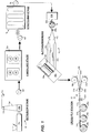
- the microporous membrane is prepared generally utilizing an extrusion stage 10, an annealing stage 12, and a stretching stage 14.
- the extrusion stage 10 involves extruding a tubular non-porous film parison 10a using a circular extrusion die 10b associated with a conventional polymer extruder 10c. Air is introduced upwardly through the extrusion die so as to form the parison 10a (i.e., so-called "blown film extrusion").
- the parison 10a is collapsed using rollers 10d, 10e and collected as a roll 10f.
- the preferred polymer from which the non-porous precursor film is made is most preferably an olefinic resin, e.g., polypropylene or polyethylene.
- olefinic resin e.g., polypropylene or polyethylene.
- other resins may also be employed depending, for example, upon the particular battery components with which the separators of this invention are intended to be used.
- the roll 10f is then annealed during the annealing stage 12 in an annealing or heat-treating oven 12a.
- the annealing stage 12 serves to increase the size of the crystallites and remove imperfections therein.
- annealing is carried out at a temperature in the range of between about 5 0 C to 100 0 C below the melting point of the polymer for a period of a few seconds to several hours (e.g., 5 seconds to 24 hours, and more preferably from about 30 seconds to 2 hours).
- the preferred annealing temperature is in the range of between about 100 0 C and 155 0 C.
- the annealed non-porous film 10f is ready for processing in the stretching stage to form micropores therein and to impart the uniaxial orientation.
- the stretching stage involves generally the sequential steps of cold stretching, followed by sequential hot stretching of the starting non-porous film as is more fully described in the Isaacson et al '764, Biernbaum et al '761, and Druin et al '538 patents cited above.
- the resulting microporous membrane material (which is still in the form of a collapsed parison) is retrieved at the end of the stretching stage 14 in the form of a roll 18.
- the pores of the microporous membrane material forming roll 18 are essentially interconnected through tortuous paths which may extend from one exterior surface or surface region to another (i.e., open-celled).
- the microporous membrane will thus exhibit a reduced bulk density as compared with the density of their corresponding precursor film having no open-celled structure.
- the microporous membranes will typically have a bulk density of no greater than about 95%, and usually between about 50% and 70% of the starting non-porous precursor film.
- the pores of the microporous membrane are, moreover, microscopic -- i.e., the details of the pore configuration or arrangement are described only in terms of microscopic dimensions.
- the open cells or pores in the membranes are smaller than those which can be measured using an ordinary light microscope, because the wavelength of visible light, which is about 5,000 ⁇ , is longer than the longest planar or surface dimension of the open cell or pore.
- the pore size of the microporous membranes may be defined by using electron microscopy techniques which are capable of resolving details of pore structure below 5,000 ⁇ or by mercury porosimitry techniques.
- the average effective pore size of the microporous membranes useable in the battery separators of this invention is preferably between 50 to 5,000 ⁇ , and more typically between 150 to 5,000 ⁇ .
- average effective pore size is meant the smallest dimension of a pore which would allow a generally spherical particle of that same dimension to pass therethrough.
- the pores generally are defined by a plurality of elongated, non-porous, interconnecting surface regions which have their axes of elongation substantially parallel to each other, and substantially normal or perpendicular to the direction in which the film was stretched during the stretching stage 14.
- Substantially alternating with and defined by the non-porous regions is a plurality of elongated, porous surface regions which contain a plurality of parallel fibrils.
- the fibrils are connected at each of their ends to a non-porous region, and are substantially perpendicular with respect to such non-porous regions.
- Between the fibrils are the pores which thus have an elongated shape with a width of from about 50 to 5,000 ⁇ and a length of from about 500 to 10,000 ⁇ .
- the "average effective pore size" will be determined by the width dimension of the pores.
- the membrane from forming roll 18 is uniaxially oriented in the stretching (machine) direction during the stretching step 14.
- such uniaxial orientation of the roll is biased relative to the lengthwise direction of the membrane using a bias or spiral slitting/rewinding station 20.
- the preferred slitting/rewinding station is, in and of itself conventional. Apparatus that may be employed in the practice of this invention include those described or shown in U.S. Patent Nos.
- the roll of uniaxially oriented microporous collapsed tubular membrane 18 obtained from the stretching step 14 is supported by unwinding supports 20a.
- the roll 18 of microporous membrane is thus unwound at the slitting/rewind station 20 in axial opposition to support mandrels 20b associated with the rewinding station.
- a flow of air in axial opposition to the tubular membrane being unwound from roll 18 should be employed so as to assist in opening of the tubular membrane.
- the opened uniaxially oriented tubular membrane supported by mandrels 20b, as well as the unwind frame 20a which supports the roll 18, are collectively rotated (arrow 20c) about the axis of the mandrel 20b by means of unwind motor 20d as the tubular membrane advances to the cutting station 20f.
- the inflated tubular membrane is cut by a knife or blade (not show) at position 20f, which is fixed relative to the mandrels 20b at a desired angle relative to the mandrel axis (e.g., 30 0 to 60 0 ).
- the cut sheet is pulled from the mandrels 20b at the same angle as the cut at position 20f by a winding unit 20g and is wound into a roll 18a.
- the membrane wound onto roll 18a will be oriented at a bias relative to the longitudinal axis of the film which is commensurate with the bias at which the tubular film was cut at position 20f.
- the tubular membrane 18 obtained from the stretching step 14 is greater than about 5 gm/in, the tubular membrane needs to be preopened before being directed to the slitting/rewinding station 20 -- an acceptable, but not preferred, situation. Preopening could be accomplished on a separate piece of equipment, or by trapping an air bubble between the roll 18 and the nip rollers 20a 1 (or "S" wrapping) associated with the support 20a.
- the interply adhesion in the uniaxially oriented microporous collapsed tubular membrane 18 obtained from the stretching step 14 be less that about 5 gm/in so as to avoid preopening of the tubular membrane in advance of the slitting/rewinding station 20.
- At least two sheets of microporous membrane may now be cross-ply laminated to one another in order to form the continuous battery separators according to the present invention.
- each of the membrane layers forming the battery separator will have been formed from the slitting/rewinding station 20. That is, each of the layers of microporous membrane forming the separator according to this invention will exhibit anisotropic mechanical properties which are angularly biased relative to the elongate axis of the membrane and will, moreover, be laminated one to another in face contact such that the orientations of the membrane layers are respectively angularly biased (i.e., cross-plied).
- the cross-ply station 22 is supplied with microporous membrane unwound from at least two of the rolls 18a obtained from the slitting/rewinding station 20 in such a manner that the angular bias of one of the membranes is offset relative to the angular bias of the other membrane.
- the cross-ply station 22 needs to have orientation at an angular bias relative to the elongate direction of the membrane, while the other membrane could have an orientation parallel to the membrane's elongate axis (i.e., a conventional machine direction oriented membrane sheet).
- the resulting laminated membrane would thereby still have the orientation of each layer angularly oriented relative to one another, albeit at a lesser angle. Suffice it to say, that the principles embodied in the present invention may be used and/or modified to obtain a laminated multiply microporous battery separator whereby the orientation of the individual layers are angularly biased relative to one another at virtually any desired angle.
- the microporous membrane is unwound from each of the rolls 18a in face to face relationship in order to ensure an angular bias is established between the two membrane layers. That is, the technical face of one membrane layer is brought into contact with the technical face of the other membrane layer so that the angular bias of the membrane is opposite to one another.
- the microporous membrane is cut at an angle of about 45 0 at the slitting/rewinding station 20, then the relative angular bias as between the orientation of the membrane layers will be about 90 0 , even though the orientation of each membrane layer are at an angle of 45 0 relative to the elongate axis of the laminated membrane.
- Lamination of the microporous membrane layers to form the separator according to this invention may be accomplished using heat and pressure supplied by the nip rollers 22a.
- the pressures applied between the nip rollers of between about 300 psi and 450 psi and roll surface temperatures of between about 110 0 C and 140 0 C have been found to be particularly suitable to bond polyethylene or polyethylene and polypropylene layers together at a line speed of between about 15 fpm and 50 fpm.
- membrane lamination by be accomplished using an adhesive applied to the face of one or both of the layers by means of adhesive applicator 22b before they are brought into physical contact at nip 22a.
- adhesive applicator 22b Preferably the adhesive is sprayed onto the film faces by any conventional techniques such as air atomization, ultrasonic spray or the like, but it is anticipated that printing techniques such as gravure coating may also be practiced.
- Virtually any adhesive may be used that is compatible with the microporous membrane, the electrochemical cell environment in which the laminated separator is intended to be used, and the method of application.
- One such material that may be used is the commercially available water based ethylene vinyl acetate AirFlex 400 made by Air Products and Chemicals Inc., of Allentown, PA.
- adhesive droplet sizes of between 1 and 100 microns and adhesive add-on of about 0.03 gm/ft 2 or less have been found to not adversely impact the porosity or permeability characteristics of the resulting laminated microporous battery separator sheet compared to a similar non-laminated sheet. This, of course, will depend upon the specific applicator used.
- lamination of the plies could be accomplished by point (or line or pattern) bonding with heat and pressure or ultrasonics.
- cross-ply lamination regardless of the technique employed, should preferably attain an interply adhesion of about 5 gm/in or greater to insure the plies do not delaminate during further processing. There is also some evidence that higher adhesion promotes higher puncture strength.
- the cross-plied laminated sheet exits the nip rolls 22a and may be slit in a lengthwise direction via knife blades 22c (only one of which is visible in FIGURE 1) to form individual cross-plied microporous separator sheets 24a-24c which are wound into rolls 26a-26c respectively.
- the widthwise dimension of sheets 24a-24c is selected so as to be suitable for the battery cells in which the separator sheets are used.
- a roll of the separator sheets 26a-26c will be unwound and interposed between layers of the anode and cathode materials forming the battery cell.
- These juxtaposed anode, separator sheet and cathode layers will then be cut to desired length and spirally or serpentinely folded so as to be inserted within the external housing (called a "can" in art parlance) of the battery.
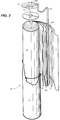
- FIGURE 2 schematically depicts an exemplary battery cell BC in which a cross-plied separator sheet 24a according to this invention is employed.
- the battery cell BC includes anode and cathode layers 30, 32, respectively, between which continuous lengths of separator sheets 24a are interposed.
- This composite structure is spirally wound about a centrally located mandrel (not shown) so as to form a generally cylindrical cell 34 which is housed within can 36.
- mandrel not shown
- other geometric forms of the cell 34 are possible, such as a serpentine-shaped cell in which the anode, separator sheet and cathode layers 30, 24a and 32, respectively, are folded in a back-and-forth serpentine manner so as to fit within a generally rectangular-shaped can.
- anode and cathode ribbon tabs 40, 42 are connected to the center pin 44a of cap 44.
- the anode ribbon tab 40 is connected to the exterior periphery of the cap 44 and thus is electrically connected through the can 36 to the anode pin (not shown) at an opposite end of the cap 44.
- An insulating disc 46 prevents short-circuiting from occurring between the anode and cathode ribbon tabs 40, 42.
- the cross-plied separator sheets according to this invention preferably has a thickness of no greater than about 3 mils, most preferably 0.5 to 1.5 mil (thickness, however, maybe be greater if the specific application requires such), and permeability characteristics of less than about 45 sec-in 2 as measured with a high pressure Gurley Densometer available from Teledyne Gurley, Troy, NY (hereinafter referred to as "Gurley Values").
- Gurley Values a high pressure Gurley Densometer available from Teledyne Gurley, Troy, NY
- Gurley Value This value is measured using a Model 4120 or 4150 Gurley Densometer from Teledyne Gurley, and is the time in seconds required to pass 10 cc of air through 1 in 2 of membrane at a constant pressure of 12.2 in of water.
- Puncture Strength Ten measurements are made across the width of the laminated product and averaged.
- a Mitech Stevens LFRA Texture Analyzer is used for the test. The needle is 1.65mm in diameter with a 0.5mm radius tip. The rate of descent is 2mm/sec and the maximum amount of deflection is 6mm. The film is held taut in a clamping device with a central opening 11.3mm in diameter.
- the film was subsequently annealed to increase the size of the lamella. It was then cold stretched in the longitudinal or machine direction at room temperature to break open the areas between the lamella, hot stretched in the same direction to open the areas between the lamella to form tortuous micropores through the film, and finally heat set to control shrinkage.
- the resulting microporous membrane had a high degree of orientation in the machine direction.
- the flat microporous membrane tube was then spirally slit.
- the tube was reopened by air and/or mechanical means (mandrel) and rotated about its axis while being slit by a cutting device set at some angle between parallel and perpendicular to the axis of rotation (typically 45°).
- the resulting single ply flat sheet product was wound onto a roll which had its axis perpendicular to the direction of cutting. It should be noted that, prior to slitting, the direction of orientation was the same as the longitudinal or machine direction which was along the axis of the tube. After spiral slitting, the direction of orientation was at some angle to the "new" machine direction, the angle being defined by the angle of the cutter to the axis of the tube and the take-up.
- the commercially available Celgard® 2400 Polypropylene Microporous Membrane has a thickness of about 1 mil, a Gurley value of between 20 to 45 sec-in 2 , and a puncture strength of about 350 gm.
- Table 1 One Ply Two Ply Cross-Ply Thickness (mil) 0.50 1.02 1.0 Gurley (sec-in 2 ) 8 14 17 Puncture strength (gm) 212 334 533
- Example 2 Another cross-plied laminate was prepared as in Example 1 except that the laminate was bonded using a commercially available water-based EVA adhesive (AirFlex 400 from Air Products and Chemicals, Co. of Allentown, PA) which was sprayed on the face of one ply using an air atomizing spray nozzle. Care was taken to apply enough adhesive to bond the plies sufficiently to prevent delamination during later process, but without a significant increase in thickness or decrease in porosity. As show in Table 2 below, the resulting product had significantly higher puncture strength compared to the two ply product in which the orientation of the layers were not biased with respect to one another. Table 2 One Ply Two Ply Cross-Ply Thickness (mil) 0.49 1.02 1.12 Gurley (sec-in 2 ) 14 22 29 Puncture strength (gm) 212 392 510
- microporous membrane separator sheets may be provided in accordance with the principles of this invention without significant increase in the thickness and/or permeability characteristics as compared to a single ply microporous membrane separator sheet. That is, the cross-plied microporous membrane separator sheets according to this invention exhibit increased strength as compared to two-ply separators having their orientation in the same direction.
- the separator sheets of this invention are particularly useful for battery cell constructions which require continuous seamless separator sheets such as in cylindrical or prismatic battery cells in which the internal anode, cathode and interposed separator sheet layers are spirally wound or accordion folded, respectively.
Landscapes
- Chemical & Material Sciences (AREA)
- Chemical Kinetics & Catalysis (AREA)
- Electrochemistry (AREA)
- General Chemical & Material Sciences (AREA)
- Engineering & Computer Science (AREA)
- Mechanical Engineering (AREA)
- Composite Materials (AREA)
- Manufacturing & Machinery (AREA)
- Cell Separators (AREA)
- Secondary Cells (AREA)
- Laminated Bodies (AREA)
- Primary Cells (AREA)
- Shaping By String And By Release Of Stress In Plastics And The Like (AREA)
Applications Claiming Priority (2)
| Application Number | Priority Date | Filing Date | Title |
|---|---|---|---|
| US362048 | 1994-12-22 | ||
| US08/362,048 US5667911A (en) | 1994-11-17 | 1994-12-22 | Methods of making cross-ply microporous membrane battery separator, and the battery separators made thereby |
Publications (2)
| Publication Number | Publication Date |
|---|---|
| EP0723304A2 true EP0723304A2 (de) | 1996-07-24 |
| EP0723304A3 EP0723304A3 (de) | 1996-08-28 |
Family
ID=23424483
Family Applications (1)
| Application Number | Title | Priority Date | Filing Date |
|---|---|---|---|
| EP95119693A Withdrawn EP0723304A2 (de) | 1994-12-22 | 1995-12-14 | Verfahren zur Herstellung von mikropöroser kreuzweise geschichteter Batterieseparatormembrane und so hergestellte Batterieseparatoren |
Country Status (6)
| Country | Link |
|---|---|
| US (1) | US5667911A (de) |
| EP (1) | EP0723304A2 (de) |
| JP (2) | JP3440176B2 (de) |
| KR (1) | KR100362331B1 (de) |
| CN (1) | CN1075248C (de) |
| TW (1) | TW294845B (de) |
Cited By (3)
| Publication number | Priority date | Publication date | Assignee | Title |
|---|---|---|---|---|
| US6830849B2 (en) | 2000-01-10 | 2004-12-14 | Lg Chemical Co., Ltd. | High crystalline polypropylene microporous membrane, multi-component microporous membrane and methods for preparing the same |
| US8741469B2 (en) | 2009-10-15 | 2014-06-03 | Samsung Sdi Co., Ltd. | Electrode assembly with multiple separators wound about a winding center |
| CN108305978A (zh) * | 2018-01-09 | 2018-07-20 | 深圳中兴创新材料技术有限公司 | 一种锂离子电池复合隔膜及其制备方法 |
Families Citing this family (50)
| Publication number | Priority date | Publication date | Assignee | Title |
|---|---|---|---|---|
| TW297171B (de) * | 1994-12-20 | 1997-02-01 | Hoechst Celanese Corp | |
| US5601997A (en) | 1995-02-03 | 1997-02-11 | Tchao; Ruy | Chemotaxis assay procedure |
| TW412542B (en) * | 1995-12-25 | 2000-11-21 | Asahi Chemical Ind | Short-resistant micro-porous polyethylene membrane |
| CA2313645A1 (en) * | 1997-12-31 | 1999-07-08 | George I. Tay | Battery separator |
| KR100477582B1 (ko) * | 1998-01-23 | 2005-08-05 | 주식회사 새 한 | 다공성분리막의제조방법 |
| US6322923B1 (en) | 1998-01-30 | 2001-11-27 | Celgard Inc. | Separator for gel electrolyte battery |
| US6080507A (en) * | 1998-04-13 | 2000-06-27 | Celgard Inc. | Trilayer battery separator |
| US6368742B2 (en) | 1998-06-26 | 2002-04-09 | Celgard, Inc. | Polypropylene microporous membrane for battery separator |
| US6346350B1 (en) * | 1999-04-20 | 2002-02-12 | Celgard Inc. | Structurally stable fusible battery separators and method of making same |
| US6602593B1 (en) | 1999-08-30 | 2003-08-05 | Celgard Inc. | Battery separators with reduced splitting propensity |
| US20020136945A1 (en) * | 2000-01-18 | 2002-09-26 | Call Ronald W. | Multilayer battery separators |
| US6432586B1 (en) | 2000-04-10 | 2002-08-13 | Celgard Inc. | Separator for a high energy rechargeable lithium battery |
| KR100336395B1 (ko) * | 2000-06-12 | 2002-05-10 | 홍지준 | 리튬 이차 전지의 제조방법 |
| US6921608B2 (en) * | 2000-07-11 | 2005-07-26 | Celgard, Inc. | Battery separator |
| US7063917B2 (en) | 2001-02-21 | 2006-06-20 | Ahlstrom Mount Holly Springs, Llc | Laminated battery separator material |
| JP2002273684A (ja) * | 2001-03-14 | 2002-09-25 | Sumitomo Chem Co Ltd | 電池セパレーター用樹脂フィルム状物のスリット方法および電池セパレーター用樹脂フィルム状物 |
| US6881515B2 (en) * | 2001-05-08 | 2005-04-19 | Celgard Inc. | Separator for polymer battery |
| JP3765396B2 (ja) * | 2001-08-20 | 2006-04-12 | ソニー株式会社 | 電池 |
| US8007940B2 (en) * | 2001-12-11 | 2011-08-30 | Eveready Battery Company, Inc. | High discharge capacity lithium battery |
| US20050112462A1 (en) * | 2003-11-21 | 2005-05-26 | Marple Jack W. | High discharge capacity lithium battery |
| US6998193B2 (en) | 2001-12-28 | 2006-02-14 | Policell Technologies, Inc. | Microporous membrane and its uses thereof |
| US6815123B2 (en) * | 2001-12-28 | 2004-11-09 | Policell Technologies, Inc. | Lithium-ion battery using heat-activatable microporous membrane |
| US6878226B2 (en) * | 2002-01-08 | 2005-04-12 | Wei-Ching Yu | Continuous methods of making microporous battery separators |
| JP4744773B2 (ja) * | 2002-05-23 | 2011-08-10 | パナソニック株式会社 | リチウムイオン二次電池 |
| US6610353B1 (en) * | 2002-09-23 | 2003-08-26 | The Gillette Co. | Method of applying adhesive to electrochemical cell components |
| CN100446304C (zh) * | 2003-03-07 | 2008-12-24 | 鸿富锦精密工业(深圳)有限公司 | 电池隔板 |
| US20040241550A1 (en) * | 2003-05-28 | 2004-12-02 | Wensley C. Glen | Battery separator for lithium polymer battery |
| US7087343B2 (en) * | 2003-07-15 | 2006-08-08 | Celgard, Inc. | High melt integrity battery separator for lithium ion batteries |
| US20050031943A1 (en) * | 2003-08-07 | 2005-02-10 | Call Ronald W. | Battery separator and method of making same |
| KR100560158B1 (ko) * | 2003-09-29 | 2006-03-16 | 주식회사 코캄 | 고 안전성 리튬 이차 전지 및 그 제조방법 |
| US20050233214A1 (en) * | 2003-11-21 | 2005-10-20 | Marple Jack W | High discharge capacity lithium battery |
| US8283071B2 (en) | 2003-11-21 | 2012-10-09 | Eveready Battery Company, Inc. | High discharge capacity lithium battery |
| US8124274B2 (en) * | 2003-11-21 | 2012-02-28 | Eveready Battery Company, Inc. | High discharge capacity lithium battery |
| US20050287425A1 (en) * | 2004-06-25 | 2005-12-29 | Celgard Inc. | Li/MnO2 battery separators with selective ion transport |
| CN100372151C (zh) * | 2004-08-13 | 2008-02-27 | 深圳市雄韬电源科技有限公司 | 铅酸蓄电池电极隔板和制作方法 |
| US20070202394A1 (en) * | 2006-02-28 | 2007-08-30 | Viavattine Joseph J | Separator systems for batteries |
| US20070238017A1 (en) | 2006-04-07 | 2007-10-11 | Celgard Llc | Multilayer separator exhibiting improved strength and stability |
| CN105347404A (zh) * | 2007-09-28 | 2016-02-24 | 永备电池有限公司 | 合成黄铁矿的制备方法 |
| KR101620944B1 (ko) * | 2008-02-06 | 2016-05-16 | 소니 가부시끼가이샤 | 세퍼레이터 및 이것을 이용한 전지 |
| JP2010027617A (ja) * | 2009-10-01 | 2010-02-04 | Panasonic Corp | リチウムイオン二次電池 |
| US20140377397A1 (en) * | 2011-05-17 | 2014-12-25 | Ole-Bendt Rasmussen | Apparatus for manufacture of a polymer film, which is oriented under an angle to its longitudinal direction |
| CN102263220B (zh) * | 2011-06-22 | 2014-09-24 | 广东博特动力能源有限公司 | 电池隔膜的制备方法 |
| KR101464430B1 (ko) * | 2013-03-13 | 2014-11-21 | 삼성토탈 주식회사 | 미세다공성 막의 제조 방법 및 상기 방법으로 제조된 막을 이용한 이차전지용 분리막 |
| JP2016516279A (ja) | 2013-03-15 | 2016-06-02 | セルガード エルエルシー | リチウム・イオン二次電池用の多層ハイブリッド電池セパレータおよびその製造方法 |
| CN103753936A (zh) * | 2014-01-17 | 2014-04-30 | 成都芝田高分子材料有限公司 | 锂电池隔膜复合装置及其复合方法 |
| JP2016072233A (ja) * | 2014-09-29 | 2016-05-09 | 株式会社Gsユアサ | 蓄電素子、及び蓄電素子の製造方法 |
| CN105470433B (zh) * | 2014-09-29 | 2020-06-23 | 株式会社杰士汤浅国际 | 蓄电元件和蓄电元件的制造方法 |
| US9931756B2 (en) * | 2014-12-25 | 2018-04-03 | Sumitomo Chemical Company, Limited | Method for producing separator and method for slitting |
| CN108604657B (zh) * | 2016-01-29 | 2021-02-23 | 住友化学株式会社 | 隔膜的卷曲量测定方法、分切装置及卷曲量测定装置 |
| KR102642401B1 (ko) * | 2019-03-13 | 2024-02-28 | 주식회사 엘지화학 | 가교 폴리올레핀 분리막의 제조방법 |
Citations (14)
| Publication number | Priority date | Publication date | Assignee | Title |
|---|---|---|---|---|
| US1365485A (en) | 1920-06-05 | 1921-01-11 | Guest Harold Augustine Tolley | Holder for the burning of candles |
| US1753645A (en) | 1924-04-18 | 1930-04-08 | Walter Prior | Machine for cutting bias strips |
| US1955282A (en) | 1931-12-19 | 1934-04-17 | Lever Bias Machine Corp | Bias cutting and wind-up apparatus |
| US2110856A (en) | 1936-02-01 | 1938-03-15 | Lever Bias Machine Corp | Bias cutting and wind-up apparatus |
| US2644522A (en) | 1950-08-15 | 1953-07-07 | Callaway Mills Co | Bias cutting machine |
| US3558764A (en) | 1966-09-06 | 1971-01-26 | Celanese Corp | Process for preparing microporous film |
| US3679538A (en) | 1970-10-28 | 1972-07-25 | Celanese Corp | Novel open-celled microporous film |
| US3843761A (en) | 1973-05-30 | 1974-10-22 | Celanese Corp | Process for preparing a thermoplastic microporous film involving a cold stretching step and multiple hot stretching steps |
| SU499364A1 (ru) | 1972-05-22 | 1976-01-15 | Орловский научно-исследовательский институт легкого машиностроения | Устройство дл разрезани по винтовой линии трубчатой ткани |
| US4439260A (en) | 1982-05-17 | 1984-03-27 | Mobil Oil Corporation | Method and apparatus for forming cross-laminated thermoplastic film |
| US4650730A (en) | 1985-05-16 | 1987-03-17 | W. R. Grace & Co. | Battery separator |
| US4809413A (en) | 1986-04-14 | 1989-03-07 | Windmoller & Holscher | Apparatus for helically slitting a continuous tubular film of synthetic thermoplastic material |
| US4907323A (en) | 1988-03-15 | 1990-03-13 | Hexcel Corporation | Method and apparatus for making biased fabric |
| US5248366A (en) | 1988-06-24 | 1993-09-28 | Rasmussen O B | Method for helical cutting of a flexible tubular sheet of polymeric material |
Family Cites Families (12)
| Publication number | Priority date | Publication date | Assignee | Title |
|---|---|---|---|---|
| GB816607A (en) * | 1954-10-04 | 1959-07-15 | Rasmussen O B | Method of manufacturing a thin band of a high molecular substance, which is orientated in a direction other than the length direction |
| US4078124A (en) * | 1969-10-09 | 1978-03-07 | Exxon Research & Engineering Co. | Laminated non-woven sheet |
| US3853601A (en) * | 1972-04-18 | 1974-12-10 | Celanese Corp | Hydrophilic microporous film |
| JPS5259825A (en) * | 1975-11-12 | 1977-05-17 | Matsushita Electric Industrial Co Ltd | Zinc alkaline battery |
| US4078123A (en) * | 1976-12-23 | 1978-03-07 | Varta Batterie Aktiengesellschaft | Spiral-wrapped multi-layer cell separator |
| JPS57203516A (en) * | 1981-06-10 | 1982-12-13 | Mitsui Petrochem Ind Ltd | Manufacture of skew-oriented, laminated, stretched film |
| JPS5912559A (ja) * | 1982-07-09 | 1984-01-23 | Hitachi Maxell Ltd | 有機電解質電池 |
| JPS59173948A (ja) * | 1983-03-19 | 1984-10-02 | Hitachi Maxell Ltd | 電池用セパレ−タの打抜き方法 |
| US4640730A (en) * | 1985-03-22 | 1987-02-03 | Ashland Oil, Inc. | Method of adhering roofing materials |
| JPS6372063A (ja) * | 1986-09-12 | 1988-04-01 | Toshiba Battery Co Ltd | 非水電解液電池 |
| US4902589A (en) * | 1988-06-08 | 1990-02-20 | Moli Energy Limited | Electrochemical cells, electrodes and methods of manufacture |
| US5350471A (en) * | 1993-05-03 | 1994-09-27 | Mirek Planeta | Production of cross-laminated film from tube |
-
1994
- 1994-12-22 US US08/362,048 patent/US5667911A/en not_active Expired - Fee Related
-
1995
- 1995-12-01 TW TW084112844A patent/TW294845B/zh not_active IP Right Cessation
- 1995-12-14 EP EP95119693A patent/EP0723304A2/de not_active Withdrawn
- 1995-12-21 KR KR1019950053447A patent/KR100362331B1/ko not_active Expired - Fee Related
- 1995-12-22 JP JP33441595A patent/JP3440176B2/ja not_active Expired - Fee Related
- 1995-12-22 CN CN95120142A patent/CN1075248C/zh not_active Expired - Fee Related
-
2001
- 2001-10-05 JP JP2001309710A patent/JP3502370B2/ja not_active Expired - Fee Related
Patent Citations (15)
| Publication number | Priority date | Publication date | Assignee | Title |
|---|---|---|---|---|
| US1365485A (en) | 1920-06-05 | 1921-01-11 | Guest Harold Augustine Tolley | Holder for the burning of candles |
| US1753645A (en) | 1924-04-18 | 1930-04-08 | Walter Prior | Machine for cutting bias strips |
| US1955282A (en) | 1931-12-19 | 1934-04-17 | Lever Bias Machine Corp | Bias cutting and wind-up apparatus |
| US2110856A (en) | 1936-02-01 | 1938-03-15 | Lever Bias Machine Corp | Bias cutting and wind-up apparatus |
| US2644522A (en) | 1950-08-15 | 1953-07-07 | Callaway Mills Co | Bias cutting machine |
| US3558764A (en) | 1966-09-06 | 1971-01-26 | Celanese Corp | Process for preparing microporous film |
| US3679538A (en) | 1970-10-28 | 1972-07-25 | Celanese Corp | Novel open-celled microporous film |
| SU499364A1 (ru) | 1972-05-22 | 1976-01-15 | Орловский научно-исследовательский институт легкого машиностроения | Устройство дл разрезани по винтовой линии трубчатой ткани |
| US3843761A (en) | 1973-05-30 | 1974-10-22 | Celanese Corp | Process for preparing a thermoplastic microporous film involving a cold stretching step and multiple hot stretching steps |
| US4439260A (en) | 1982-05-17 | 1984-03-27 | Mobil Oil Corporation | Method and apparatus for forming cross-laminated thermoplastic film |
| US4650730A (en) | 1985-05-16 | 1987-03-17 | W. R. Grace & Co. | Battery separator |
| US4731304A (en) | 1985-05-16 | 1988-03-15 | W. R. Grace & Co. | Battery separator |
| US4809413A (en) | 1986-04-14 | 1989-03-07 | Windmoller & Holscher | Apparatus for helically slitting a continuous tubular film of synthetic thermoplastic material |
| US4907323A (en) | 1988-03-15 | 1990-03-13 | Hexcel Corporation | Method and apparatus for making biased fabric |
| US5248366A (en) | 1988-06-24 | 1993-09-28 | Rasmussen O B | Method for helical cutting of a flexible tubular sheet of polymeric material |
Cited By (4)
| Publication number | Priority date | Publication date | Assignee | Title |
|---|---|---|---|---|
| US6830849B2 (en) | 2000-01-10 | 2004-12-14 | Lg Chemical Co., Ltd. | High crystalline polypropylene microporous membrane, multi-component microporous membrane and methods for preparing the same |
| US8741469B2 (en) | 2009-10-15 | 2014-06-03 | Samsung Sdi Co., Ltd. | Electrode assembly with multiple separators wound about a winding center |
| CN108305978A (zh) * | 2018-01-09 | 2018-07-20 | 深圳中兴创新材料技术有限公司 | 一种锂离子电池复合隔膜及其制备方法 |
| CN108305978B (zh) * | 2018-01-09 | 2022-08-02 | 深圳中兴新材技术股份有限公司 | 一种锂离子电池复合隔膜及其制备方法 |
Also Published As
| Publication number | Publication date |
|---|---|
| KR100362331B1 (ko) | 2003-03-06 |
| CN1075248C (zh) | 2001-11-21 |
| TW294845B (de) | 1997-01-01 |
| JP3440176B2 (ja) | 2003-08-25 |
| JP2002184381A (ja) | 2002-06-28 |
| CN1134043A (zh) | 1996-10-23 |
| US5667911A (en) | 1997-09-16 |
| EP0723304A3 (de) | 1996-08-28 |
| JP3502370B2 (ja) | 2004-03-02 |
| JPH08236098A (ja) | 1996-09-13 |
| KR960027006A (ko) | 1996-07-22 |
Similar Documents
| Publication | Publication Date | Title |
|---|---|---|
| US5667911A (en) | Methods of making cross-ply microporous membrane battery separator, and the battery separators made thereby | |
| EP0892448B1 (de) | Dreilagiger, mikroporöser Batterieseparator und Herstellverfahren | |
| KR100512540B1 (ko) | 삼층 배터리 분리기의 제조 방법 | |
| US6602593B1 (en) | Battery separators with reduced splitting propensity | |
| EP3329530B1 (de) | Verbesserte laminierte mehrschichtmembranen, separatoren, batterien und verfahren | |
| US9908317B2 (en) | Multilayer battery separators | |
| US20210320377A1 (en) | Low electrical resistance microporous battery separator membranes, separators, cells, batteries, and related methods | |
| US5691047A (en) | Porous multi-layer film | |
| KR101656413B1 (ko) | 전기화학소자용 분리막의 제조방법 및 그로부터 제조된 전기화학소자용 분리막 | |
| JP4516796B2 (ja) | 電池セパレータおよびその製造方法 | |
| JP3381538B2 (ja) | 積層多孔質ポリオレフィンフイルムの製法 | |
| JPH08236093A (ja) | バッテリーセパレーター | |
| EP0924780B1 (de) | Fünflagiger Batterieseparator | |
| JP3436055B2 (ja) | 電池用セパレータ | |
| JPH11115084A (ja) | 積層多孔質フイルム | |
| JPH09117959A (ja) | 積層多孔質ポリオレフィンフイルムの製法 | |
| KR100371390B1 (ko) | 다층구조격리막 |
Legal Events
| Date | Code | Title | Description |
|---|---|---|---|
| PUAI | Public reference made under article 153(3) epc to a published international application that has entered the european phase |
Free format text: ORIGINAL CODE: 0009012 |
|
| PUAL | Search report despatched |
Free format text: ORIGINAL CODE: 0009013 |
|
| AK | Designated contracting states |
Kind code of ref document: A2 Designated state(s): DE FR GB NL |
|
| AK | Designated contracting states |
Kind code of ref document: A3 Designated state(s): DE FR GB NL |
|
| RHK1 | Main classification (correction) |
Ipc: H01M 2/16 |
|
| 17P | Request for examination filed |
Effective date: 19960913 |
|
| 17Q | First examination report despatched |
Effective date: 19971002 |
|
| RAP1 | Party data changed (applicant data changed or rights of an application transferred) |
Owner name: CELGARD LLC |
|
| STAA | Information on the status of an ep patent application or granted ep patent |
Free format text: STATUS: THE APPLICATION HAS BEEN WITHDRAWN |
|
| 18W | Application withdrawn |
Withdrawal date: 19991016 |