EP0723816A2 - Procédé et dispositif pour distribuer de la mousse à deux composants - Google Patents
Procédé et dispositif pour distribuer de la mousse à deux composants Download PDFInfo
- Publication number
- EP0723816A2 EP0723816A2 EP96100054A EP96100054A EP0723816A2 EP 0723816 A2 EP0723816 A2 EP 0723816A2 EP 96100054 A EP96100054 A EP 96100054A EP 96100054 A EP96100054 A EP 96100054A EP 0723816 A2 EP0723816 A2 EP 0723816A2
- Authority
- EP
- European Patent Office
- Prior art keywords
- components
- dispensing
- mixing
- foam
- foam material
- Prior art date
- Legal status (The legal status is an assumption and is not a legal conclusion. Google has not performed a legal analysis and makes no representation as to the accuracy of the status listed.)
- Withdrawn
Links
- 239000006260 foam Substances 0.000 title claims abstract description 41
- 238000000034 method Methods 0.000 title claims abstract description 15
- 239000006261 foam material Substances 0.000 claims abstract description 23
- 239000007788 liquid Substances 0.000 claims description 25
- 238000002347 injection Methods 0.000 claims description 12
- 239000007924 injection Substances 0.000 claims description 12
- 230000003750 conditioning effect Effects 0.000 claims description 10
- 239000011324 bead Substances 0.000 claims description 5
- 239000000243 solution Substances 0.000 claims description 3
- 238000005086 pumping Methods 0.000 claims 1
- 239000007789 gas Substances 0.000 description 25
- 229920005862 polyol Polymers 0.000 description 20
- 150000003077 polyols Chemical class 0.000 description 20
- 239000000463 material Substances 0.000 description 16
- 238000010926 purge Methods 0.000 description 10
- 230000000712 assembly Effects 0.000 description 9
- 238000000429 assembly Methods 0.000 description 9
- 239000002904 solvent Substances 0.000 description 9
- 239000000758 substrate Substances 0.000 description 8
- 230000006911 nucleation Effects 0.000 description 7
- 238000010899 nucleation Methods 0.000 description 7
- 239000012948 isocyanate Substances 0.000 description 6
- 150000002513 isocyanates Chemical class 0.000 description 6
- 238000006243 chemical reaction Methods 0.000 description 5
- XLYOFNOQVPJJNP-UHFFFAOYSA-N water Substances O XLYOFNOQVPJJNP-UHFFFAOYSA-N 0.000 description 5
- 230000000694 effects Effects 0.000 description 3
- IJGRMHOSHXDMSA-UHFFFAOYSA-N Atomic nitrogen Chemical compound N#N IJGRMHOSHXDMSA-UHFFFAOYSA-N 0.000 description 2
- CURLTUGMZLYLDI-UHFFFAOYSA-N Carbon dioxide Chemical compound O=C=O CURLTUGMZLYLDI-UHFFFAOYSA-N 0.000 description 2
- 230000002411 adverse Effects 0.000 description 2
- 238000013461 design Methods 0.000 description 2
- 238000005187 foaming Methods 0.000 description 2
- 238000012423 maintenance Methods 0.000 description 2
- 239000000203 mixture Substances 0.000 description 2
- 230000000704 physical effect Effects 0.000 description 2
- 230000008092 positive effect Effects 0.000 description 2
- 229920005830 Polyurethane Foam Polymers 0.000 description 1
- 230000004888 barrier function Effects 0.000 description 1
- 229910002092 carbon dioxide Inorganic materials 0.000 description 1
- 239000001569 carbon dioxide Substances 0.000 description 1
- 230000008859 change Effects 0.000 description 1
- 238000004140 cleaning Methods 0.000 description 1
- 150000001875 compounds Chemical class 0.000 description 1
- 238000001816 cooling Methods 0.000 description 1
- 230000008878 coupling Effects 0.000 description 1
- 238000010168 coupling process Methods 0.000 description 1
- 238000005859 coupling reaction Methods 0.000 description 1
- 238000010586 diagram Methods 0.000 description 1
- 239000000428 dust Substances 0.000 description 1
- 239000012530 fluid Substances 0.000 description 1
- 239000004088 foaming agent Substances 0.000 description 1
- 238000010438 heat treatment Methods 0.000 description 1
- 238000007373 indentation Methods 0.000 description 1
- 239000011261 inert gas Substances 0.000 description 1
- 238000003780 insertion Methods 0.000 description 1
- 230000037431 insertion Effects 0.000 description 1
- 238000009413 insulation Methods 0.000 description 1
- 230000007246 mechanism Effects 0.000 description 1
- 238000012986 modification Methods 0.000 description 1
- 230000004048 modification Effects 0.000 description 1
- 229910052757 nitrogen Inorganic materials 0.000 description 1
- -1 polyurethane Chemical class 0.000 description 1
- 229920002635 polyurethane Polymers 0.000 description 1
- 239000004814 polyurethane Substances 0.000 description 1
- 239000011496 polyurethane foam Substances 0.000 description 1
- 239000000565 sealant Substances 0.000 description 1
- 238000007789 sealing Methods 0.000 description 1
- 239000008149 soap solution Substances 0.000 description 1
- 238000003756 stirring Methods 0.000 description 1
- 238000011144 upstream manufacturing Methods 0.000 description 1
Images


Classifications
-
- B—PERFORMING OPERATIONS; TRANSPORTING
- B29—WORKING OF PLASTICS; WORKING OF SUBSTANCES IN A PLASTIC STATE IN GENERAL
- B29C—SHAPING OR JOINING OF PLASTICS; SHAPING OF MATERIAL IN A PLASTIC STATE, NOT OTHERWISE PROVIDED FOR; AFTER-TREATMENT OF THE SHAPED PRODUCTS, e.g. REPAIRING
- B29C44/00—Shaping by internal pressure generated in the material, e.g. swelling or foaming ; Producing porous or cellular expanded plastics articles
- B29C44/34—Auxiliary operations
- B29C44/3442—Mixing, kneading or conveying the foamable material
-
- B—PERFORMING OPERATIONS; TRANSPORTING
- B29—WORKING OF PLASTICS; WORKING OF SUBSTANCES IN A PLASTIC STATE IN GENERAL
- B29B—PREPARATION OR PRETREATMENT OF THE MATERIAL TO BE SHAPED; MAKING GRANULES OR PREFORMS; RECOVERY OF PLASTICS OR OTHER CONSTITUENTS OF WASTE MATERIAL CONTAINING PLASTICS
- B29B7/00—Mixing; Kneading
- B29B7/30—Mixing; Kneading continuous, with mechanical mixing or kneading devices
- B29B7/34—Mixing; Kneading continuous, with mechanical mixing or kneading devices with movable mixing or kneading devices
- B29B7/38—Mixing; Kneading continuous, with mechanical mixing or kneading devices with movable mixing or kneading devices rotary
- B29B7/40—Mixing; Kneading continuous, with mechanical mixing or kneading devices with movable mixing or kneading devices rotary with single shaft
- B29B7/401—Mixing; Kneading continuous, with mechanical mixing or kneading devices with movable mixing or kneading devices rotary with single shaft having a casing closely surrounding the rotor, e.g. with a plunger for feeding the material
-
- B—PERFORMING OPERATIONS; TRANSPORTING
- B29—WORKING OF PLASTICS; WORKING OF SUBSTANCES IN A PLASTIC STATE IN GENERAL
- B29B—PREPARATION OR PRETREATMENT OF THE MATERIAL TO BE SHAPED; MAKING GRANULES OR PREFORMS; RECOVERY OF PLASTICS OR OTHER CONSTITUENTS OF WASTE MATERIAL CONTAINING PLASTICS
- B29B7/00—Mixing; Kneading
- B29B7/30—Mixing; Kneading continuous, with mechanical mixing or kneading devices
- B29B7/34—Mixing; Kneading continuous, with mechanical mixing or kneading devices with movable mixing or kneading devices
- B29B7/38—Mixing; Kneading continuous, with mechanical mixing or kneading devices with movable mixing or kneading devices rotary
- B29B7/40—Mixing; Kneading continuous, with mechanical mixing or kneading devices with movable mixing or kneading devices rotary with single shaft
- B29B7/404—Mixing; Kneading continuous, with mechanical mixing or kneading devices with movable mixing or kneading devices rotary with single shaft with feeding or valve actuating means, e.g. with cleaning means
-
- B—PERFORMING OPERATIONS; TRANSPORTING
- B29—WORKING OF PLASTICS; WORKING OF SUBSTANCES IN A PLASTIC STATE IN GENERAL
- B29B—PREPARATION OR PRETREATMENT OF THE MATERIAL TO BE SHAPED; MAKING GRANULES OR PREFORMS; RECOVERY OF PLASTICS OR OTHER CONSTITUENTS OF WASTE MATERIAL CONTAINING PLASTICS
- B29B7/00—Mixing; Kneading
- B29B7/30—Mixing; Kneading continuous, with mechanical mixing or kneading devices
- B29B7/34—Mixing; Kneading continuous, with mechanical mixing or kneading devices with movable mixing or kneading devices
- B29B7/38—Mixing; Kneading continuous, with mechanical mixing or kneading devices with movable mixing or kneading devices rotary
- B29B7/40—Mixing; Kneading continuous, with mechanical mixing or kneading devices with movable mixing or kneading devices rotary with single shaft
- B29B7/405—Mixing heads
- B29B7/407—Mixing heads with a casing closely surrounding the rotor, e.g. with conical rotor
-
- B—PERFORMING OPERATIONS; TRANSPORTING
- B29—WORKING OF PLASTICS; WORKING OF SUBSTANCES IN A PLASTIC STATE IN GENERAL
- B29B—PREPARATION OR PRETREATMENT OF THE MATERIAL TO BE SHAPED; MAKING GRANULES OR PREFORMS; RECOVERY OF PLASTICS OR OTHER CONSTITUENTS OF WASTE MATERIAL CONTAINING PLASTICS
- B29B7/00—Mixing; Kneading
- B29B7/30—Mixing; Kneading continuous, with mechanical mixing or kneading devices
- B29B7/58—Component parts, details or accessories; Auxiliary operations
- B29B7/60—Component parts, details or accessories; Auxiliary operations for feeding, e.g. end guides for the incoming material
- B29B7/603—Component parts, details or accessories; Auxiliary operations for feeding, e.g. end guides for the incoming material in measured doses, e.g. proportioning of several materials
-
- B—PERFORMING OPERATIONS; TRANSPORTING
- B29—WORKING OF PLASTICS; WORKING OF SUBSTANCES IN A PLASTIC STATE IN GENERAL
- B29B—PREPARATION OR PRETREATMENT OF THE MATERIAL TO BE SHAPED; MAKING GRANULES OR PREFORMS; RECOVERY OF PLASTICS OR OTHER CONSTITUENTS OF WASTE MATERIAL CONTAINING PLASTICS
- B29B7/00—Mixing; Kneading
- B29B7/74—Mixing; Kneading using other mixers or combinations of mixers, e.g. of dissimilar mixers ; Plant
- B29B7/7404—Mixing devices specially adapted for foamable substances
-
- B—PERFORMING OPERATIONS; TRANSPORTING
- B29—WORKING OF PLASTICS; WORKING OF SUBSTANCES IN A PLASTIC STATE IN GENERAL
- B29B—PREPARATION OR PRETREATMENT OF THE MATERIAL TO BE SHAPED; MAKING GRANULES OR PREFORMS; RECOVERY OF PLASTICS OR OTHER CONSTITUENTS OF WASTE MATERIAL CONTAINING PLASTICS
- B29B7/00—Mixing; Kneading
- B29B7/74—Mixing; Kneading using other mixers or combinations of mixers, e.g. of dissimilar mixers ; Plant
- B29B7/7404—Mixing devices specially adapted for foamable substances
- B29B7/7409—Mixing devices specially adapted for foamable substances with supply of gas
- B29B7/7414—Mixing devices specially adapted for foamable substances with supply of gas with rotatable stirrer, e.g. using an intermeshing rotor-stator system
-
- B—PERFORMING OPERATIONS; TRANSPORTING
- B29—WORKING OF PLASTICS; WORKING OF SUBSTANCES IN A PLASTIC STATE IN GENERAL
- B29B—PREPARATION OR PRETREATMENT OF THE MATERIAL TO BE SHAPED; MAKING GRANULES OR PREFORMS; RECOVERY OF PLASTICS OR OTHER CONSTITUENTS OF WASTE MATERIAL CONTAINING PLASTICS
- B29B7/00—Mixing; Kneading
- B29B7/74—Mixing; Kneading using other mixers or combinations of mixers, e.g. of dissimilar mixers ; Plant
- B29B7/7404—Mixing devices specially adapted for foamable substances
- B29B7/7433—Plants
-
- B—PERFORMING OPERATIONS; TRANSPORTING
- B29—WORKING OF PLASTICS; WORKING OF SUBSTANCES IN A PLASTIC STATE IN GENERAL
- B29C—SHAPING OR JOINING OF PLASTICS; SHAPING OF MATERIAL IN A PLASTIC STATE, NOT OTHERWISE PROVIDED FOR; AFTER-TREATMENT OF THE SHAPED PRODUCTS, e.g. REPAIRING
- B29C44/00—Shaping by internal pressure generated in the material, e.g. swelling or foaming ; Producing porous or cellular expanded plastics articles
- B29C44/34—Auxiliary operations
- B29C44/60—Measuring, controlling or regulating
Definitions
- This invention relates to foam materials produced from a chemical reaction by mixing two liquid components, and in particular to a system for dispensing the foam material and applying the foam material to a substrate.
- Foam products produced in this manner can be used as sealants which provide barriers against air, dust, vapor and fluids in various applications. They also find application in providing thermal or sound insulation layers.
- the foam is created by a chemical reaction between the two liquid components.
- the chemical reaction occurs, creating a new compound, such as polyurethane, which is the foamed material, and creating a foaming agent, such as carbon dioxide, which is entrained within with the foamed material to create the foam. Since the chemical reaction occurs almost instantaneously, the two liquid components must be mixed together in a dispensing head immediately prior to applying the foam material onto the substrate.
- Another consideration is the separate maintenance of each of the components prior to dispensing and the proper mixing of the components in the dispensing head. Since the components when mixed will almost instantly react to produce the foamed product, it is important that the components remain separate and that mixing of the components is avoided until immediately prior to dispensing the foam onto a substrate. For this purpose, a dispensing head or gun must be used in which the two components can be mixed and in which the mixture is then immediately applied to the substrate.
- Another consideration is the maintenance of the dispensing head or gun in a clean condition. After the liquid components have been mixed together in the head, the foam product is created, and this foam product can build up along the dispensing flow path inside the gun. This build-up of foam material must be cleaned from the gun periodically, and for this purpose a purge system is usually provided.
- the purge system is used to provide a supply of an appropriate cleaning solvent to the dispensing flow path of the gun to clean the flow path.
- the foam product is not dispensed continually onto the substrate. Instead, the dispensing flow is turned on and off, and this intermittent operation of the dispensing bead must be accommodated.
- the dispensing flow is turned on and off, there can be intermittent increases in pressure of the lines supplying the liquid components to the dispensing bead. These pressure increases can affect the flow rate of the components, and, if the mass flow rate of one component varies relative to the other component, the components will not be mixed in the proper proportion, causing an adverse effect to the properties and appearance of the foam product being dispensed.
- open-ended systems provide for proper temperature conditioning of the components.
- the components are normally supplied to the dispensing head at room temperature.
- maintaining the components at the proper temperature can be difficult if temperatures in which the system is operated vary significantly from a normal room temperature.
- the component supply tanks are often maintained in a temperature bath. Since open-ended systems recirculate the components back to the supply tanks when dispensing the foam product is interrupted, the components are constantly being recirculated back to the temperature controlled tanks. The recirculation maintains a constant supply of the components at the proper temperature.
- the components are not allowed to stagnate in the lines and are not allowed to be exposed to ambient temperatures for any significant period of time.
- recirculation in open-ended systems avoids pressure gradients and allows for proper temperature conditioning of the components
- recirculation also present certain problems, particularly with high viscosity materials.
- High viscosity materials experience more pressure losses when being recirculated, and the energy created by these pressure losses can cause the materials to heat up, creating additional problems.
- recirculation of the components presents problems when gas injection or nucleation is used, since it becomes difficult to accurately control the amount of gas being injected into the components when they are being recirculated.
- Gas injection or nucleation has been shown to have positive effects upon the mixing and dispensing of many components m two component foam systems, such as polyol used in a polyol/isocyanate system.
- the gas injection has often been accomplished in the prior art by simply injecting gas into one of the component supply tanks, with the flow of gas simply' bubbled through the liquid in the tank. While this simple gas injection method accomplished the desired purposes of providing nucleation, there was no control of the amount of gas being entrained in the component.
- the varying amount of gas injected in the component during the nucleation changed the density of the component/gas mixture and made it more difficult to control the proper mass flow of this component with respect to the other component to provide the proper ratio of components to the dispensing head.
- the present invention provides a unique two component foaming system that handles these and other problems.
- the system of the present invention is a "closed-ended" system in which the liquid components which are used to produce the foam are not being constantly recirculated. Instead, the components flow through the supply lines to the dispensing head only when the foam is being dispensed onto the substrate. When the dispensing of the foam product from the head is interrupted, the flow of the liquid components through the supply lines to the dispensing head is stopped.
- This closed-ended design eliminates many of the components needed for recirculation and provides a simpler and more reliable system.
- the closed ended system allows for the addition of gas injection or nucleation to the system.
- Pressure transients in the supply lines and the proper ratio of the components are controlled by using metering pumps to accurately meter the flow of the liquid components and ⁇ to supply the proper mass flow rate of each component so that the supplies of components are properly matched.
- the metering pumps can be located at location distant from the dispensing head. The metering pumps provide for an accurate allocation of each component, so that the resulting ratio of components provided to the dispensing head is more precise. By maintaining a more precise ratio of the liquid components, the resulting foam product is more uniform in physical properties as well as appearance.
- high pressure pumps are used to pump the components from the supply tanks.
- the use of high pressure pumps allows the metering pumps to perform their metering function without requiring the metering pumps to also be the main apparatus for moving the flow of components.
- the high pressure pumps thus reduce the pressure differential across the metering pumps, increasing the accuracy of the metering pumps and reducing wear.
- the high pressure pumps also act to reduce the effects on the air entrained in the materials taken from the supply tanks. By removing the materials under high pressure, the pumps collapse the entrained air bubbles in the material.
- the resulting material metered by the metering pumps has a more consistent density and can be more accurately metered.
- the problem of temperature deviations in the supply lines is resolved by providing a temperature conditioning environment in the supply lines.
- the lines are each provided with an outer jacket into which water or some other temperature conditioning liquid circulates.
- the outer jacket is connected to a temperature conditioning unit which supplies the water to the jacket at the desired temperature.
- the temperature conditioning unit either heats or chills the water as necessary, and the water at the proper temperature is circulated in the outer jackets to maintain the liquid component in the inner supply line at the proper temperature.
- gas injection or nucleation for one or both of the components: it can be accomplished by injecting a precise amount of gas into one of the component supply hoses downstream of the metering pump. In this way: the mass flow of the component is accurately metered by the metering pump, this metering is not affected by the amount of gas injected into the component downstream of the pump, and the proper mass flow of component is supplied to the dispensing head.
- the method comprises the steps of maintaining separate reservoirs of at least two different components which react chemically with one another when combined to produce the foam material, providing a dispensing head for mixing the components immediately prior to dispensing the foam material and for dispensing the foam intermittently therefrom, and withdrawing the components from the reservoirs and supplying the components to the dispensing head only when the foam material is dispensed.
- the apparatus of the present invention is a mixing and dispensing system for mixing and dispensing at least two different components which react chemically with one another when combined to produce a foam product.
- the system comprises at least two tanks, each containing one of the components; a mixing and dispensing head having a plurality of flow inlets and an outlet, the mixing and dispensing head intermittently dispensing the foam product from the outlet and mixing the two components together to form the foam product immediately prior to dispensing; supply lines connected to the liquid flow inlets of the mixing and dispensing head, the components flowing to the mixing and dispensing head through the supply lines when the foam product is dispensed, the components being held in the supply lines when the foam product is not being dispensed and flow of components is interrupted; metering pumps for supplying the different components under pressure to the supply lines, the metering pumps including controls for adjusting the pressure at which at least one of the components is supplied to the supply lines when the flow of the components is interrupted; and a temperature conditioner connected to the supply lines for maintaining the temperature of the
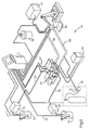
- FIG. 1 is a schematic diagram of the two-component foam dispensing system embodying the method and apparatus of the present invention.
- FIG. 2 is a side sectional view of a mixing and dispensing head for use with the method and apparatus of the present invention.
- FIG. 3 is a top plan of the mixing and dispensing head taken along line 3 ⁇ 3 of FIG. 2 .
- the system 10 comprises a control console 11 which contains all of the control circuits for operating the system.
- the system 10 also comprises two supply tanks 12 and 13 , each providing a reservoir containing one of components which will be combined to form the foamed product.
- a first component is contained in the supply tank 12
- a second component is contained in the other supply tank 13 .
- the system 10 disclosed is a two-component foam system comprising polyol and isocyanate which combine to form polyurethane foam.
- the first component contained in the supply tank 12 is polyol
- the second component contained in the supply tank 13 is isocyanate. It should be understood, however, that the system 10 can be used in other two-component foam combinations with the intended advantages.
- the supply tanks 12 and 13 may be suitable supply tanks, which preferably each include an automatic stirring mechanism as is known in the art. Each of the supply tanks 12 and 13 may contain suitable level controls to monitor the amount of material in each tank, and each of the supply tanks is connected to the control console 11 by control lines 16 and 17 .
- high pressure pumps 20 and 21 are used to feed the components from the supply tanks 12 and 13 through suitable supply hoses 22 and 23 to metering pumps 24 .
- the metering pumps 24 are essentially the same as those shown in U.S. Patent No. 5,271,521 and U.S. Patent No. 5,332,125, the disclosures of which are hereby incorporated by reference in their entirety.
- the metering pumps may comprise a pair of gear-type motor-driven pumps. The volume at which each component is supplied by the pumps is controlled by the speed of a variable speed motor used to drive a gear of that pump.
- the two pumps are coupled or linked electrically such that the ratio of the volume or mass dispensed from one metering pump is in proportion to the volume or mass dispensed from the other pump.
- the metering pumps 24 are operated under control from the control console 11 and are connected to the control console 11 by control lines 27 .
- the high pressure pumps 20 and 21 operate at around 300-500 psi and serve two purposes. First, they keep the pressure drop across the metering pumps 24 as low as possible. This allows the metering pumps to more accurately meter the flow rates of the components and reduces the wear on the metering pumps. Second, the high pressures created by the pumps 20 and 21 force any gas entrained within the components to be forced into solution, creating a liquid of more consistent density which can be more accurately pumped and metered.
- the metering pumps 24 accurately meter the proper mass ratio of each of the two components from the supply tanks 12 and 13 and supply a mass flow according to this proper ratio through supply hoses 28 and 29 to a mixing and dispensing head 30 .
- the supply hoses 28 and 29 from the metering pumps 24 to the mixing and dispensing head 30 are preferably jacketed to control the temperature of the components in the supply hose by circulating a liquid in the outer jacket.
- a temperature conditioning unit 33 supplies cooling or heating liquid, such as water, to the outer jacket of the supply hoses 28 and 29 .
- the control console 11 may also be connected to the temperature conditioning unit 33 by suitable control lines (not shown).
- gas may be injected into the polyol supply hose 28 at the exit to the metering pump 24 , if desired.
- the control console 11 may be connected to a gas injection system 36 by suitable electrical lines, and a precise amount of a relatively inert gas, such as nitrogen, can be injected into the polyol supply hose 28 downstream of the metering pump 24 .
- the mass flow metering of the component is not affected by the amount of gas that is injected into the component, and maintaining the proper ratio of components is not adversely affected by gas injection.
- Polyol or other components may contain some gas when they are received from a supplier, and it may be necessary to provide a suitable system for extracting air from the polyol before the polyol is placed in the supply tank.
- the air-free polyol could then be accurately metered by the metering pump, and a proper amount of gas could then be re-injected into the polyol by the gas injection system. This would enhance the accuracy of the metering of the polyol in the dispensing system.
- some system for determining the air in the polyol tank could be provided with the metering pumps and the gas injection system being adjusted according to this determination.
- the high pressure pumps 20 and 21 which serve to force the entrained air into solution do not necessarily extract the air from the components, but they do assure that a uniform liquid flow is provided throughout the system.
- the two components are mixed according to the accurate ratios of each component supplied to the mixing and dispensing head by the metering pumps 24 , and dispensed onto a substrate 39 .
- the mixing and dispensing head 30 is also connected to a purge system comprising a solvent supply 40 and an air supply 41 .
- the purge system is used to purge or clean the head 30 as needed.
- the solvent may be any suitable solvent.
- a preferred solvent can be a soap solution as it is relatively benign and does not present any safety hazards. The actual solvent used will depend upon the materials in the system.
- the mixing dispensing head 30 is shown in more detail in FIG. 2 and is more fully described in co-pending patent application, entitled “Dispensing Head for Two-Component Foam,” filed on the same date as the filing of this application and assigned to the same assignee.
- the head 30 comprises a main body 42 with a bearing housing 43 attached to the upper end.
- a platform 44 is formed on the upper end of the bearing housing 43 , and an electric servo motor 45 is mounted on the platform 44 by means of screws 46 .
- a rotatable motor shaft 47 extends downwardly from the motor 45 through an opening in the platform 44 into the bearing housing 43.
- the motor shaft 47 is connected to a drive shaft 48 by means of a coupling 49 .
- the drive shaft 48 extends vertically through a central opening in the bearing housing 43 , where it is journalled in bearings 51 , and extends into a coaxial central opening in the main body 42 .
- a mixing shaft 52 is mounted on the lower end of the drive shaft 48 .
- the mixing shaft 52 rotates within a mixing chamber 53 formed at the lower end of the central opening in the main body 42 .
- a suitable sealing device 54 is provided around the lower end of the drive shaft to seal upper end of the mixing chamber 53 .
- Extending horizontally outwardly from the main body 42 are a plurality of supply valve assemblies 58 a , 58 b and 58 c (FIG. 3).
- supply valve assemblies 58 a , 58 b and 58 c there are three supply valve assemblies 58 a , 58 b and 58 c , two supply valve assemblies 58 a and 58 b for the polyol, and one supply valve assembly 58 c for the isocyanate.
- Two supply valve assemblies are provided for the polyol, to allow the user to connect the mixing and dispensing head to two different supplies of polyol, such as to change the color of the dispensed material.
- only one polyol supply valve assembly is necessary.
- the supply valve assemblies extend horizontally in a direction generally perpendicularly to each other.
- the supply valve assembly 58 a is perpendicular to the supply valve assembly 58 b
- the supply valve assembly 58 b is perpendicular to the supply valve assembly 58 c .
- the supply valve assembly 58 a is thus opposite the supply valve assembly 58 b .
- a purge valve assembly 59 is opposite the other supply valve assembly 58 b .
- the purge valve assembly 59 includes a port 60 which provides an inlet for connection to the solvent supply 40 and a port 61 which provides an inlet for connection to the air supply 41 , both as previously described.
- the purge valve assembly 59 allows the purge solvent and high pressure air to be introduced into the mixing chamber 53 to clean the chamber of component residue as needed.
- the purge valve assembly 59 also includes a check valve to prevent components from flowing back to the solvent and air supplies 40 and 41 .
- the supply valve assembly 58 a is pneumatically operated "zero cavity" valve, comprising a body 64 a which is mounted on the main body 42 .
- a port 67 a is provided on one side of the body 64 a for insertion of a suitable connection to a supply hose, such as one of the supply hoses 28 and 29 shown in FIG. 1.
- the component material from the supply hose enters the body 64 a through the port and enters into a supply chamber 68 a formed within the body 64 a .
- the supply chamber 68 a is connected to the mixing chamber 53 within the main body 42 , and a valve seat is provided between the supply chamber 68 a and the mixing chamber 53 .
- a needle valve member 69 a is mounted in a guide member 70 a mounted in the downstream portion of the chamber 68 a .
- the needle valve member 69 a extends through the chamber 68 a and engages the valve seat to control the flow of component material from the supply chamber 68 a into the mixing chamber 53 .
- the valve head formed by the needle valve member 69 a is at the maximum position downstream so that there is no cavity of residual material downstream in the supply chamber prior to entering the mixing chamber.
- the needle valve member 69 a is actuated through a pneumatic actuation formed within the body 64 a .
- the upper portion of the mixing shaft 52 comprises a portion which rotates in the upper portion of the mixing chamber 53 and which is contacted by the component material exiting from the supply valve assembly 58 a .
- the supply valve assembly 58 a is vertically offset from the supply valve assembly 58 c , so that the components enter the mixing chamber 53 at different vertical levels.
- the level of the supply valve assemblies 58 a and 58 b is vertically above the level of the supply valve assembly 58 c , so that the polyol is introduced into the mixing chamber 53 upstream of the isocyanate.
- impingement mixers of the prior art in which the components enter the mixing chamber opposite each other and mixing is accomplished by shooting the components at each other in the mixing chamber.
- an enlarged mixing chamber 83 formed within a tubular extension 84 mounted on the lower portion of the main body 42 .
- a cylindrical mixing core 85 having an array of indentations and outwardly extending angled vanes 86 .
- the mixing core 85 is mounted to the lower end of the mixing shaft 52 , and the core rotates within the enlarged mixing chamber 83 as the mixing shaft turns.
- the vanes 86 create turbulence which mixes the components supplied from the supply valve assemblies 58 until the components are thoroughly mixed together to create the chemical reaction which produces the foam which is then ready to be dispensed from the mixing and dispensing head 30 .
- the mixing chamber 53 tapers to a dispensing channel 89 .
- a flow shutoff assembly 90 which prevents residual portions of the mixed components from dripping or dribbling from the head when the supply valve assemblies have been closed.
- the flow shutoff assembly 90 comprises a flexible tube 91 which is attached at the lower end of the dispensing channel 89 , and the mixed components which are dispensed by the head enter the flexible tube 91 after exiting from the dispensing channel 89 .
- Adjacent to the lower end of the flexible tube 91 are pincher fingers 92 .
- the pincher fingers 92 are capable of moving inwardly to compress or pinch the tube 91 to stop the flow of mixed components from the end of the tube.
- a piston/collet member 93 is positioned around the pincher fingers 92 .
- the piston/collet member 93 has a lower portion forming a tubular actuating toilet 94 and an integral upper portion forming a piston 95 .
- the pincher fingers 92 are cammed inwardly by the vertically movable actuating collet 94 which surrounds the fingers.
- the lower end of the fingers 92 have camming surfaces 96 which extend radially outwardly from the flexible tube 91 . As the actuating collet 94 moves downwardly, it engages the camming surfaces 96 of the fingers 92 and forces the fingers 92 radially inwardly to pinch the tube 91 and cut off the flow of product from the tube.
- the piston 95 fits around the exterior of the extension 84 , and a ring 99 , which is attached to the lower end of the main body 42 , fits around the flange 98 and around exterior of the piston 95 .
- the piston/collet member 93 is moved by actuation of pneumatic chambers and/or springs formed between the ring 99 and the piston 95 .
Landscapes
- Engineering & Computer Science (AREA)
- Mechanical Engineering (AREA)
- Processing And Handling Of Plastics And Other Materials For Molding In General (AREA)
- Nozzles (AREA)
- Feeding, Discharge, Calcimining, Fusing, And Gas-Generation Devices (AREA)
Applications Claiming Priority (2)
| Application Number | Priority Date | Filing Date | Title |
|---|---|---|---|
| US37972095A | 1995-01-27 | 1995-01-27 | |
| US379720 | 1995-01-27 |
Publications (2)
| Publication Number | Publication Date |
|---|---|
| EP0723816A2 true EP0723816A2 (fr) | 1996-07-31 |
| EP0723816A3 EP0723816A3 (fr) | 1997-06-04 |
Family
ID=23498407
Family Applications (1)
| Application Number | Title | Priority Date | Filing Date |
|---|---|---|---|
| EP96100054A Withdrawn EP0723816A3 (fr) | 1995-01-27 | 1996-01-04 | Procédé et dispositif pour distribuer de la mousse à deux composants |
Country Status (3)
| Country | Link |
|---|---|
| EP (1) | EP0723816A3 (fr) |
| JP (1) | JPH08229939A (fr) |
| CA (1) | CA2165372A1 (fr) |
Cited By (9)
| Publication number | Priority date | Publication date | Assignee | Title |
|---|---|---|---|---|
| WO1999048601A1 (fr) * | 1998-03-25 | 1999-09-30 | Remco Sijtze Schoppen | Melangeur/distributeur multicomposant |
| US6206669B1 (en) * | 1994-01-14 | 2001-03-27 | Compsys, Inc. | System for continuously manufacturing a composite preform |
| EP1591225A3 (fr) * | 2004-04-30 | 2007-01-24 | Duna-Corradini S.r.l. | Méthode et dispositif pour réguler la température d'un fluide le long d'un tube d'alimentation |
| WO2013182467A1 (fr) * | 2012-06-06 | 2013-12-12 | Henkel Ag & Co. Kgaa | Installation de moussage |
| JP2018529544A (ja) * | 2015-07-03 | 2018-10-11 | ゾンダホフ エンジニアリング ゲゼルシャフト ミット ベシュレンクテル ハフツングSonderhoff Engineering GmbH | 圧力保持装置を備えた混合装置 |
| RU194516U1 (ru) * | 2018-12-14 | 2019-12-12 | Общество с ограниченной ответственностью "Редиус 168" | Установка для приготовления двухкомпонентных составов в виде реверсивного поршневого насоса |
| EP4197729A1 (fr) * | 2021-12-20 | 2023-06-21 | Henkel AG & Co. KGaA | Dispositif de mélange destiné à la fourniture d'une matière plastique moussée ou pouvant être moussée |
| DE102023133274A1 (de) * | 2023-11-28 | 2025-05-28 | Atlas Copco Ias Gmbh | Applikationsvorrichtung und Verfahren zum Herstellen einer Mehrkomponentenmischung und Ein/Aufbringen der Mehrkomponentenmischung in/auf einen Gegenstand, sowie Applikationssystem umfassend die Applikationsvorrichtung |
| DE102023133271A1 (de) * | 2023-11-28 | 2025-05-28 | Atlas Copco Ias Gmbh | Applikationsvorrichtung und Verfahren zum Herstellen einer Mehrkomponentenmischung und Ein-/Aufbringen der Mehrkomponentenmischung in/auf einen Gegenstand, sowie Applikationssystem umfassend die Applikationsvorrichtung |
Families Citing this family (1)
| Publication number | Priority date | Publication date | Assignee | Title |
|---|---|---|---|---|
| JP4001220B2 (ja) * | 2001-04-23 | 2007-10-31 | 関東自動車工業株式会社 | 低温硬化2液型ポリウレタン塗料の塗装方法及び装置 |
Family Cites Families (8)
| Publication number | Priority date | Publication date | Assignee | Title |
|---|---|---|---|---|
| US2779689A (en) * | 1955-07-19 | 1957-01-29 | Pittsburgh Plate Glass Co | Forming foamed polyurethane resins |
| US3091551A (en) * | 1959-01-26 | 1963-05-28 | Wyandotte Chemicals Corp | Process of spraying a polyether-based polyurethane foam |
| DE1778060B2 (de) * | 1968-03-23 | 1973-01-04 | Farbenfabriken Bayer Ag, 5090 Leverkusen | Einrichtung zum Herstellen von Kunststoffen aus miteinander reagierenden Komponenten |
| DE2440022C2 (de) * | 1974-08-21 | 1982-07-08 | Bayer Ag, 5090 Leverkusen | Verfahren zur Herstellung von Dämm- und Leichtbaustoffen und Vorrichtung zur Durchführung dieses Verfahrens |
| US4170440A (en) * | 1976-09-29 | 1979-10-09 | Gusmer Corporation | Feeder for apparatus for ejecting urethane foam formed by the mixture of resin and isocyanate with flushing liquid |
| US4246230A (en) * | 1978-04-28 | 1981-01-20 | Hasselman Sr Walter J | System for forming and dispensing a resinous foam |
| US5004159A (en) * | 1988-01-25 | 1991-04-02 | Specified Equipment Systems Company, Inc. | Method and apparatus for applying single of multicomponent materials |
| US5270014A (en) * | 1991-03-19 | 1993-12-14 | Krauss-Maffei Ag | Apparatus for producing a foamed mass of a polyurea elastomer |
-
1995
- 1995-12-15 CA CA002165372A patent/CA2165372A1/fr not_active Abandoned
-
1996
- 1996-01-04 EP EP96100054A patent/EP0723816A3/fr not_active Withdrawn
- 1996-01-29 JP JP8012405A patent/JPH08229939A/ja active Pending
Cited By (13)
| Publication number | Priority date | Publication date | Assignee | Title |
|---|---|---|---|---|
| US6206669B1 (en) * | 1994-01-14 | 2001-03-27 | Compsys, Inc. | System for continuously manufacturing a composite preform |
| WO1999048601A1 (fr) * | 1998-03-25 | 1999-09-30 | Remco Sijtze Schoppen | Melangeur/distributeur multicomposant |
| EP1591225A3 (fr) * | 2004-04-30 | 2007-01-24 | Duna-Corradini S.r.l. | Méthode et dispositif pour réguler la température d'un fluide le long d'un tube d'alimentation |
| WO2013182467A1 (fr) * | 2012-06-06 | 2013-12-12 | Henkel Ag & Co. Kgaa | Installation de moussage |
| CN104364006A (zh) * | 2012-06-06 | 2015-02-18 | 汉高股份有限及两合公司 | 发泡设备 |
| US9687795B2 (en) | 2012-06-06 | 2017-06-27 | Henkel Ag & Co. Kgaa | Foaming device |
| JP2018529544A (ja) * | 2015-07-03 | 2018-10-11 | ゾンダホフ エンジニアリング ゲゼルシャフト ミット ベシュレンクテル ハフツングSonderhoff Engineering GmbH | 圧力保持装置を備えた混合装置 |
| US11897168B2 (en) | 2015-07-03 | 2024-02-13 | Henkel Ag & Co. Kgaa | Mixing device with a pressure holding device |
| RU194516U1 (ru) * | 2018-12-14 | 2019-12-12 | Общество с ограниченной ответственностью "Редиус 168" | Установка для приготовления двухкомпонентных составов в виде реверсивного поршневого насоса |
| EP4197729A1 (fr) * | 2021-12-20 | 2023-06-21 | Henkel AG & Co. KGaA | Dispositif de mélange destiné à la fourniture d'une matière plastique moussée ou pouvant être moussée |
| WO2023117641A1 (fr) * | 2021-12-20 | 2023-06-29 | Henkel Ag & Co. Kgaa | Dispositif de mélange pour fournir un plastique expansé ou expansible |
| DE102023133274A1 (de) * | 2023-11-28 | 2025-05-28 | Atlas Copco Ias Gmbh | Applikationsvorrichtung und Verfahren zum Herstellen einer Mehrkomponentenmischung und Ein/Aufbringen der Mehrkomponentenmischung in/auf einen Gegenstand, sowie Applikationssystem umfassend die Applikationsvorrichtung |
| DE102023133271A1 (de) * | 2023-11-28 | 2025-05-28 | Atlas Copco Ias Gmbh | Applikationsvorrichtung und Verfahren zum Herstellen einer Mehrkomponentenmischung und Ein-/Aufbringen der Mehrkomponentenmischung in/auf einen Gegenstand, sowie Applikationssystem umfassend die Applikationsvorrichtung |
Also Published As
| Publication number | Publication date |
|---|---|
| CA2165372A1 (fr) | 1996-07-28 |
| JPH08229939A (ja) | 1996-09-10 |
| EP0723816A3 (fr) | 1997-06-04 |
Similar Documents
| Publication | Publication Date | Title |
|---|---|---|
| JP5495494B2 (ja) | ガス及び流体材料の混合物を吐出する装置及び方法 | |
| US3220801A (en) | Froth generator | |
| US5938079A (en) | Dispensing head for two-component foam with shutoff | |
| AU611893B2 (en) | Method and apparatus for foaming high viscosity polymer materials | |
| US3892389A (en) | Device and method for injecting liquids into a mixing head | |
| US20070000947A1 (en) | Apparatus and methods for dispensing fluidic or viscous materials | |
| US4157427A (en) | Method for entraining gas in a liquid chemical precursor for reaction injection molding | |
| US5893486A (en) | Foam dispensing device | |
| EP1875958B1 (fr) | Appareil d'alimentation en matériau de revêtement | |
| WO1996000130A1 (fr) | Distributeur ameliore a faible cout, pour mousses multicomposants | |
| EP1031776B1 (fr) | Combinaison buse d'injection/soupape pour améliorer le temps de réponse du dosage des couleurs | |
| EP0723843A2 (fr) | Tête de distribution de mousse à deux composants avec dispositif d'arrêt | |
| EP0550594A1 (fr) | Separateur de l'ecoulement de constituants chimiques | |
| JPH08229939A (ja) | 二成分発泡材料を配量する方法および装置 | |
| US20110210120A1 (en) | Apparatus and method for delivering a product into a receptacle | |
| US3236419A (en) | Foam dispenser | |
| US20080257979A1 (en) | Plural component purging system | |
| JPH04507384A (ja) | 非化学的に発泡された多成分の硬化可能ポリマーを塗布する方法及び装置 | |
| US5318637A (en) | Method of cleaning urethane foam dispensers using heated water | |
| GB1589306A (en) | Method and apparatus for mixing polyurethane foam | |
| US20180297045A1 (en) | Plural component machine, hose and spray gun system | |
| JP2709425B2 (ja) | 発泡ウレタン樹脂混合装置 | |
| JP2021529247A (ja) | 反応プラスチックの製造装置及び製造方法 | |
| CA2507467A1 (fr) | Une methode de production d'un corps polymere en mousse | |
| US3385671A (en) | Foam injection head |
Legal Events
| Date | Code | Title | Description |
|---|---|---|---|
| PUAI | Public reference made under article 153(3) epc to a published international application that has entered the european phase |
Free format text: ORIGINAL CODE: 0009012 |
|
| AK | Designated contracting states |
Kind code of ref document: A2 Designated state(s): CH DE ES FR GB IT LI |
|
| PUAL | Search report despatched |
Free format text: ORIGINAL CODE: 0009013 |
|
| AK | Designated contracting states |
Kind code of ref document: A3 Designated state(s): CH DE ES FR GB IT LI |
|
| STAA | Information on the status of an ep patent application or granted ep patent |
Free format text: STATUS: THE APPLICATION IS DEEMED TO BE WITHDRAWN |
|
| 18D | Application deemed to be withdrawn |
Effective date: 19971205 |