EP0724057A1 - Poignée rotative - Google Patents
Poignée rotative Download PDFInfo
- Publication number
- EP0724057A1 EP0724057A1 EP95117749A EP95117749A EP0724057A1 EP 0724057 A1 EP0724057 A1 EP 0724057A1 EP 95117749 A EP95117749 A EP 95117749A EP 95117749 A EP95117749 A EP 95117749A EP 0724057 A1 EP0724057 A1 EP 0724057A1
- Authority
- EP
- European Patent Office
- Prior art keywords
- handle
- bolt
- locking
- handle according
- neck
- Prior art date
- Legal status (The legal status is an assumption and is not a legal conclusion. Google has not performed a legal analysis and makes no representation as to the accuracy of the status listed.)
- Granted
Links
- 229910000831 Steel Inorganic materials 0.000 claims abstract description 16
- 239000010959 steel Substances 0.000 claims abstract description 16
- 239000011324 bead Substances 0.000 claims description 3
- 238000010079 rubber tapping Methods 0.000 claims description 2
- 241000220317 Rosa Species 0.000 claims 1
- 230000000284 resting effect Effects 0.000 abstract 1
- 230000006835 compression Effects 0.000 description 5
- 238000007906 compression Methods 0.000 description 5
- 238000004080 punching Methods 0.000 description 4
- 238000010276 construction Methods 0.000 description 3
- 238000005553 drilling Methods 0.000 description 3
- 210000003813 thumb Anatomy 0.000 description 3
- 238000002788 crimping Methods 0.000 description 2
- 230000000694 effects Effects 0.000 description 2
- 230000006978 adaptation Effects 0.000 description 1
- 238000004026 adhesive bonding Methods 0.000 description 1
- 230000000712 assembly Effects 0.000 description 1
- 238000000429 assembly Methods 0.000 description 1
- 210000003811 finger Anatomy 0.000 description 1
- 238000007373 indentation Methods 0.000 description 1
- 238000012986 modification Methods 0.000 description 1
- 230000004048 modification Effects 0.000 description 1
- 230000000149 penetrating effect Effects 0.000 description 1
- 238000009423 ventilation Methods 0.000 description 1
Images




Classifications
-
- E—FIXED CONSTRUCTIONS
- E05—LOCKS; KEYS; WINDOW OR DOOR FITTINGS; SAFES
- E05C—BOLTS OR FASTENING DEVICES FOR WINGS, SPECIALLY FOR DOORS OR WINDOWS
- E05C3/00—Fastening devices with bolts moving pivotally or rotatively
- E05C3/02—Fastening devices with bolts moving pivotally or rotatively without latching action
- E05C3/04—Fastening devices with bolts moving pivotally or rotatively without latching action with operating handle or equivalent member rigid with the bolt
- E05C3/041—Fastening devices with bolts moving pivotally or rotatively without latching action with operating handle or equivalent member rigid with the bolt rotating about an axis perpendicular to the surface on which the fastener is mounted
- E05C3/043—Fastening devices with bolts moving pivotally or rotatively without latching action with operating handle or equivalent member rigid with the bolt rotating about an axis perpendicular to the surface on which the fastener is mounted the pivot being between bolt and handle
-
- E—FIXED CONSTRUCTIONS
- E05—LOCKS; KEYS; WINDOW OR DOOR FITTINGS; SAFES
- E05B—LOCKS; ACCESSORIES THEREFOR; HANDCUFFS
- E05B13/00—Devices preventing the key or the handle or both from being used
- E05B13/10—Devices preventing the key or the handle or both from being used formed by a lock arranged in the handle
- E05B13/106—Devices preventing the key or the handle or both from being used formed by a lock arranged in the handle for handles pivoted about an axis perpendicular to the wing
-
- E—FIXED CONSTRUCTIONS
- E05—LOCKS; KEYS; WINDOW OR DOOR FITTINGS; SAFES
- E05B—LOCKS; ACCESSORIES THEREFOR; HANDCUFFS
- E05B3/00—Fastening knobs or handles to lock or latch parts
- E05B3/06—Fastening knobs or handles to lock or latch parts by means arranged in or on the rose or escutcheon
Definitions
- the invention relates to a turning handle according to the preamble of claim 1.
- a locking bolt that engages in a striking plate or in a striker on the window frame is used in particular for swing and swing-sash windows.
- the handles are arranged somewhat obliquely to the elongated screw-on box in order to achieve better access to the window frame.
- lockable or lockable window handles for securing closed windows, especially against unauthorized opening. They have a handle which is rotatably mounted in a stop body and is non-rotatably connected to an actuating square or a swiveling locking bolt. In the closed position prevents a spring-loaded locking element or a locking device, for. B. a lock cylinder, turning the window handle into the open position. The window can only be opened after the locking element or the locking cylinder has been actuated.
- a window handle provided with a step-shaped neck recess with a neck extension penetrates a stop plate which has at least one bore on its upper side.
- a sleeve is fixed in the neck recess, in which a locking bolt is axially displaceably mounted. It has a pull button at its upper end and is loaded downwards by a compression spring which is supported on the sleeve, so that in the locked position the lower end of the bolt is extended by the force of the spring and engages in one of the holes in the stop plate. It is then not possible to turn the window handle.
- To unlock the bolt is lifted by pulling the pull button axially and, if necessary, locked in an upper locking position. Even when the bolt is in the locked position, the pull button must protrude sufficiently from the top of the handle to ensure access at all. This may affect handling, especially if the button is very small.
- EP-A-0 241 245 describes a rotary handle with a shaft body rotatably mounted on a mounting plate, on which an offset operating handle engages.
- a spring-loaded piston is guided axially displaceably in a recess in the shaft. Its upper end protrudes from the surface of the shaft as a push button, while the lower end has a nose which sits over a hole in a base plate provided under the shaft. In the open position, the compression spring is relaxed and the nose end of the bolt is flush with the base plate. This has a bore from which, in the open position, a beveled bolt or bolt protrudes against the pressure of a spring.
- the shaft slides over the bolt and pushes it back into its bore until the bore of the base plate comes to rest over the bolt in the end position of the shaft. He pushes the nose of the piston back under the force of his spring and engages in the bore so that the handle is locked.
- the piston is pressed down at its upper end, which causes the latch to be lifted out of the base plate hole and the handle to be pivoted.
- the construction is relatively complex because two spring-loaded locking elements are necessary.
- the window and door closer described therein has a handle that is angled in its axis of rotation and rotatably mounted in a rosette, which is connected in a rotationally fixed manner to a locking bolt that can be swung out to the side of the rosette.
- a sleeve is arranged in which a spring-loaded bolt is axially supported with a push button, the lower end of the bolt reaching through the rosette and carrying an essentially rectangular locking plate on its inside. Both in the open and in the closed position, the locking plate rests on the inner surface of the rosette and, due to its dimensions, prevents the locking bolt from pivoting.
- a turning handle in particular a door or window handle with a handle head, the neck of which is axially fixed / rotatable on an approximately box-shaped or cap-shaped rosette, which can be fastened to a screw-on surface, for example a window frame, and forms or receives a guide bushing for the handle neck in the middle, which is rotatably connected inside the rosette with a bolt which has a laterally pivotable arm
- the invention provides according to the characterizing part of claim 1 that in the rosette a support body is supported on the screwing surface, which in turn rests has a contact surface for the bolt and a hole for the guide bush.
- This structure is as simple as it is robust. It is important that the support body supports the rosette stably so that the deformations that are possible with conventional fittings cannot occur.
- the components can be designed to be space-saving and ensure easy assembly and permanent, reliable usability.
- the carrier body is designed as a substantially rectangular, folded on the narrow sides steel plate, which has a stop angle for a latch side surface on one long side. This stop angle also causes a substantial stiffening of the structure and relieves the rosette cap, which had to take over the corresponding stop function on a longitudinal wall in conventional constructions.
- connection of the handle neck and latch is carried out according to claim 3 with the interposition of the carrier body by crimping or screwing in the axial direction and by a form-fit entrainment in the direction of rotation. It can be seen that this ensures simple assembly and, thanks to its high strength, permanent serviceability.
- the invention according to claim 4 alternatively provides that the bolt is rigidly connected or integrally with a particularly weakly conically shaped profile part, which is form-fitting in an opposite profile recess of the Handle neck engages.
- This version is particularly suitable for a screw connection that reliably absorbs large tensile and compressive forces or moments.
- the rosette and / or the support body in particular, has screw holes arranged on the narrow side, so that both components can be fastened together on the screw-on surface.
- the invention provides according to independent claim 6 that the carrier body for receiving the locking bolt end next to the guide bore has an opening with an area which is at least approximately flush with the side surface of the bolt when it is pivoted out into its closed position.
- the locking bolt end thus also penetrates the carrier body at a point selected in such a way that in its closed position the bolt rests with a side face on the locking bolt, so that the handle cannot be actuated without prior unlocking.
- So-called child safety devices have a locking bolt which is loaded by a spring towards the closed position.
- the invention provides according to claim 7 that the locking pin is guided in the grip head in a socket body on which an articulated and / or flexible actuating member is supported with the upper locking pin part.
- the articulated or flexible connection allows the direction of movement of the locking bolt to deviate from that of the actuating member, whereby a considerable gain in space can be achieved.
- the actuating member is designed as a slide which is adjustable parallel to the outer surface of the handle and has a flexible connecting part which acts in a directionally variable manner on the upper part of the locking bolt.
- the embodiment of claim 9 is very advantageous, according to which the connecting part is a plastic band with a thickened end, which is in one piece with the slider and is largely enclosed in particular by an outwardly narrowed transverse opening on the upper part of the locking bolt.
- the band is primarily subjected to tension and performs the deflection of the actuation direction out of the locking pin axis with very little effort.
- the positive connection is very simple and largely free of wear.
- the actuating member has a cover surface which at least slightly projects beyond the outer surface of the handle, which makes it easier to touch.
- the top surface can be at least partially roughened, in particular corrugated with an arrow structure, and in particular can be concave to the outside. This ensures safe actuation by the thumb of the gripping hand.
- the socket body has an outer flat part guiding the actuating member, which is fitted into an opposite recess in the grip head and is preferably fixed integrally therein.
- the flat part protrudes towards a sleeve of the socket body in the direction of the main part of the handle and therefore offers the slide the necessary possibility of movement.
- the fit in the handle head is preferably secured by gluing.
- the spring loading the locking bolt can enclose it according to claim 13 in the recess and is supported on the lower end of the socket body, that is, on the sleeve part mentioned. This measure also contributes to a low overall height.
- FIG. 14 Another design with a locking bolt, which is part of a locking cylinder attached in the neck-parallel recess of the handle head, is characterized according to claim 14 in that the bolt is supported by an additional inner plate against the screwing surface.
- the inner plate can have tabs which extend into recesses in the carrier body and screw holes which are aligned with those of the carrier body.
- the plate made of steel according to claim 16 has a central offset facing the bolt with a bore in which an intermediate ring bearing on the bolt is seated. Both the extent of the offset and the dimensioning of the intermediate ring allow a good adaptation to the local mounting conditions in such a way that the bolt and the handle firmly attached to it receive reliable support against the screwing surface.
- claims 17 to 19 ensure proper guidance and thus rotatability of the bolt, which can be attached axially to the handle head by means of a heavy-duty screw fastening, and thus the handle holds securely. It helps if the fastening screw can be anchored in a preferably slightly conical blind hole according to claim 20.
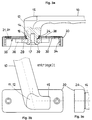
- the handle generally illustrated in FIG. 1 consists of a handle 10, the handle head 12 of which continues with a handle neck 14, a shoulder 16 and a square 18.
- the main part of the handle can be provided with (indicated) finger depressions.
- a shoulder 15 protrudes from one side at the top (see FIGS. 2b, 3b).
- a guide bush 24 which comes into contact in a bore 22 of a rosette 20, which is generally cap-shaped and is provided with screw holes 21.
- a steel plate 30 can be inserted into the rosette 20, which is also essentially rectangular in shape and has support brackets 34 on both narrow sides.
- a bore 32 is provided in the center, the clear width of which corresponds to the insert diameter of the flange-shaped guide bush 24.
- the steel plate 30 On the underside, the steel plate 30 has a contact surface 35 for a bolt 26. Furthermore, it has screw holes 31 near the support angles 34, which are assigned to the screw holes 21 of the rosette 20.
- a beveled stop bracket 36 is provided on one long side in order to limit end positions of the bolt 26, which can be pivoted by means of the handle 10.
- the latter has a square hole 28 for receiving the square 18 when assembling the fitting, its axially fixed / rotatable connection being secured by a flange 39 (FIGS. 2a, 3a).
- FIGS. 2a to 2c and FIGS. 3 to 3c The structure and function of the assembled unit can be seen from FIGS. 2a to 2c and FIGS. 3 to 3c.
- the handle 10 In the locked position, the handle 10 is at an angle to the rosette 20 so that the extension 15 of the handle and an arm or arch part 27 of the bolt project beyond the rosette 20 on one long side (FIGS. 2b, 2c). Unlocking takes place by pivoting the handle 10 upward (FIGS. 3b, 3c). It can be seen that the handle 10 can have a thumb rest 11 in the area of the handle head 12 for easy handling. It is important that the steel lower plate 30 together with the rosette 20 support the entire fitting on a (not shown) screwing surface, the screw holes 21, 31 being arranged near the ends of the box-shaped structure. Instead of a pair of holes as shown, two pairs of holes can also be provided near the corners in order to ensure even greater strength of the screw connection.
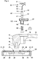
- Fig. 4 shows an exploded view of the individual part of another handle design, the handle 10 being provided with an effective child safety device on the rosette 20 and the steel plate 30. It is also located in Area of the handle head 12 parallel to the axis of the handle neck 14, a cylindrical recess 54, to which an oval recess 19 connects to the top of the handle 10. These openings serve to receive a socket body 45, which in the assembled state sits with a sleeve part 46 in the recess 54, while a flat part 55 is fitted into the recess 19 and glued therein.
- the sleeve part 46 has at the lower end a guide ring 47 for a locking bolt 40, the lower end 41 of which can be advanced into a hole 23 of the rosette and a hole 38 of the plate 30 aligned therewith.
- a compression spring 48 is held on the locking bolt by a locking washer 49 which is inserted into an annular groove 42.
- the band 52 is in one piece with a slide 50, which has a roughened top surface 51.
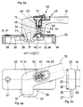
- FIGS. 5a to 5c The assembled unit and its function can be seen in FIGS. 5a to 5c in the locked position and in FIGS. 6a to 6c in the unlocked position.
- the spring 48 presses the locking pin 40 with its end 41 into the holes 23, 38 of the rosette-plate unit 20/30.
- the handle 10 cannot therefore be pivoted in relation to it.
- the connecting band 52 pulls the locking bolt 40 against the force of the spring 48 upward via the positive connection 53/44 and out of holes 38, 23 (Fig. 6a).
- the handle 10 can now be pivoted into the open position (FIG. 6b). If the slide is released, the compression spring 48 pulls it and the locking bolt 40 down again.
- a locking cylinder 59 is inserted in the handle head 12 parallel to the axis of the handle neck 14, which can be actuated with a key S in order to move the lower end of a locking bolt 40 back and forth.
- the rosette-plate unit 20/30 receives the guide bush 24 in the center, next to which the holes 23, 38 are assigned to the locking bolt 40/41.
- the latch 26 has a profile part 29, which can be designed as a square or polygon and for fitting into an opposite profile recess 56 in the handle neck 14 is determined.
- the recess 56 continues with an equally weakly conical blind hole 57.
- the bolt 26 together with the profile part 29 is axially penetrated by a through hole 25 which opens into a recess 72 on the bottom side.
- the latter is enclosed by a bead 71 which is surrounded by an annular recess 73.
- This serves to receive an intermediate ring 66, which is seated in a bore 62 of an inner steel plate 60, specifically in a central region, which is raised toward the bolt 26 by an offset 63.
- the inner steel plate 60 has screw holes 61 at the narrow ends.
- a step washer 65 can be mounted by means of a screw 67, which passes through the through hole 25 and can be drawn into the blind hole 57, so that the components 60, 26/29, 20/30 are pressed onto the handle neck 14 of the handle head 12 .
- the undersides of the main components or assemblies are shown partially pre-assembled in FIG. 8, specifically in association with the corresponding components in FIG. 7.
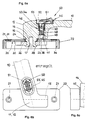
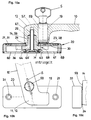
- the fitting is shown in the locked position in FIGS. 9a to 9c and in the unlocked position in FIGS. 10a to 10c.
- the inner steel plate 60 is supported on the screwing surface (not shown) and thus offers an abutment for the bolt 26 and the handle 10 screwed to it.
- the meshing of components 65, 64, 66, 26, 24, 16 ensures exact centering and free rotation with the least amount of axial play.
- the locked position (FIG. 9a) of the locking bolt 40 the handle 10 is held in the position of FIG. 9b, the bolt 26 with its arm or arch part 27 and the shoulder 15 projecting laterally over the rosette body 20.
- the handle 10 unlocked in this way can be pivoted upward (FIG. 10b).
- the bolt 26 - which is shown in Fig. 8 (center) in the pivoted-out position, the arm or arch part 27 penetrating a side slot 74 of the rosette 20 - with a side surface 68 now a rotation limitation by abutment on the stop bracket 36.
- the latch 26 is generally pointed-oval, so that the side surface 68 rolls to a certain extent on the stop bracket 36. This passes into the main part of the plate 30 with punchings 37 in order to prevent notching effects.
- the rotary handle described relates primarily to a rotary handle 10, the neck 14 of which is axially fixed / rotatable on a box-shaped rosette 20 and is non-rotatably connected on the inside to a pivotable bolt 26, has a support body 30 supported on the screw-on surface, which in turn has a contact surface 35 for the bolt 26 and is a folded steel plate 30 which has a stop angle 36 for a side surface 68 of a pointed oval bolt part.
- the bolt 26 can be rigidly connected or integrally with a conical profile part 29, which engages in a form-fitting manner in a profile recess 56 of the handle neck 14.
- a child safety device has a spring-loaded locking pin 40 in a socket body 45, in which a slide 50, which can be adjusted parallel to the outer surface of the handle, is guided with a flexible connecting part 52, which acts on the locking pin upper part 43 in a directionally variable manner and has a corrugated, concavely curved top surface 51.
- the bolt 26 can be supported by an inner steel plate 60 with respect to the screw-on surface and can be axially fixed together with the profile part 29 by means of a screw 67, which can preferably be anchored self-tapping in the handle head 12.
Landscapes
- Engineering & Computer Science (AREA)
- Mechanical Engineering (AREA)
- Lock And Its Accessories (AREA)
- Power Steering Mechanism (AREA)
Applications Claiming Priority (2)
| Application Number | Priority Date | Filing Date | Title |
|---|---|---|---|
| DE29501310U | 1995-01-27 | ||
| DE29501310U DE29501310U1 (de) | 1995-01-27 | 1995-01-27 | Drehhandhabe |
Publications (2)
| Publication Number | Publication Date |
|---|---|
| EP0724057A1 true EP0724057A1 (fr) | 1996-07-31 |
| EP0724057B1 EP0724057B1 (fr) | 1997-10-08 |
Family
ID=8003069
Family Applications (1)
| Application Number | Title | Priority Date | Filing Date |
|---|---|---|---|
| EP95117749A Expired - Lifetime EP0724057B1 (fr) | 1995-01-27 | 1995-11-10 | Poignée rotative |
Country Status (2)
| Country | Link |
|---|---|
| EP (1) | EP0724057B1 (fr) |
| DE (2) | DE29501310U1 (fr) |
Cited By (4)
| Publication number | Priority date | Publication date | Assignee | Title |
|---|---|---|---|---|
| RU2324042C2 (ru) * | 2002-07-12 | 2008-05-10 | Супериор Инвестментс Лимитед | Блокирующий механизм для двери |
| CN107642288A (zh) * | 2017-10-11 | 2018-01-30 | 皓月汽车安全系统技术股份有限公司 | 一种军车前门内开机构总成 |
| CN108045501A (zh) * | 2017-12-18 | 2018-05-18 | 无锡海核装备科技有限公司 | 带应急解锁装置的舱口盖 |
| CN111622601A (zh) * | 2020-07-01 | 2020-09-04 | 佛山市顺德区格瑞夫五金制品有限公司 | 一种门配件 |
Families Citing this family (2)
| Publication number | Priority date | Publication date | Assignee | Title |
|---|---|---|---|---|
| DE102009023130B4 (de) * | 2009-05-20 | 2017-06-08 | Hafi Beschläge GmbH | Beschlag für Fenster, Türen oder Tore |
| NL2014735B1 (en) * | 2015-04-30 | 2017-01-25 | Axa Stenman Nederland B V | Closing assembly. |
Citations (8)
| Publication number | Priority date | Publication date | Assignee | Title |
|---|---|---|---|---|
| DE1064380B (de) * | 1955-04-09 | 1959-08-27 | Hautau Baubeschlag | Sperrmechanismus fuer Fenster, Tueren u. dgl. |
| GB1537251A (en) * | 1976-03-02 | 1978-12-29 | Norcros Investments Ltd | Door and window fittings |
| GB1563806A (en) * | 1976-12-15 | 1980-04-02 | Marston & Co Ltd A | Window and like rotary deadbolt fasteners |
| DE8432060U1 (de) | 1984-11-02 | 1985-02-07 | Hoppe Gmbh & Co Kg, 3570 Stadtallendorf | Fenstergriff |
| GB2159398A (en) * | 1984-06-02 | 1985-12-04 | Cartwright R | Improvements relating to handle assemblies |
| GB2177150A (en) * | 1985-05-23 | 1987-01-14 | Smith Wallis & Co Limited | Handle |
| EP0241245A1 (fr) | 1986-04-07 | 1987-10-14 | Regent Lock Co. Ltd. | Poignée |
| NL8800104A (nl) | 1988-01-18 | 1989-08-16 | Arend Beeuwkes | Raam- en deursluiting, welke is ontworpen om te voorkomen dat een raam of deur waar de "click-lock"-sluiting op is gemonteerd kan worden gesloten of ontsloten zonder twee handelingen gelijktijdig uit te voeren. |
-
1995
- 1995-01-27 DE DE29501310U patent/DE29501310U1/de not_active Expired - Lifetime
- 1995-11-10 EP EP95117749A patent/EP0724057B1/fr not_active Expired - Lifetime
- 1995-11-10 DE DE59500772T patent/DE59500772D1/de not_active Expired - Lifetime
Patent Citations (8)
| Publication number | Priority date | Publication date | Assignee | Title |
|---|---|---|---|---|
| DE1064380B (de) * | 1955-04-09 | 1959-08-27 | Hautau Baubeschlag | Sperrmechanismus fuer Fenster, Tueren u. dgl. |
| GB1537251A (en) * | 1976-03-02 | 1978-12-29 | Norcros Investments Ltd | Door and window fittings |
| GB1563806A (en) * | 1976-12-15 | 1980-04-02 | Marston & Co Ltd A | Window and like rotary deadbolt fasteners |
| GB2159398A (en) * | 1984-06-02 | 1985-12-04 | Cartwright R | Improvements relating to handle assemblies |
| DE8432060U1 (de) | 1984-11-02 | 1985-02-07 | Hoppe Gmbh & Co Kg, 3570 Stadtallendorf | Fenstergriff |
| GB2177150A (en) * | 1985-05-23 | 1987-01-14 | Smith Wallis & Co Limited | Handle |
| EP0241245A1 (fr) | 1986-04-07 | 1987-10-14 | Regent Lock Co. Ltd. | Poignée |
| NL8800104A (nl) | 1988-01-18 | 1989-08-16 | Arend Beeuwkes | Raam- en deursluiting, welke is ontworpen om te voorkomen dat een raam of deur waar de "click-lock"-sluiting op is gemonteerd kan worden gesloten of ontsloten zonder twee handelingen gelijktijdig uit te voeren. |
Cited By (5)
| Publication number | Priority date | Publication date | Assignee | Title |
|---|---|---|---|---|
| RU2324042C2 (ru) * | 2002-07-12 | 2008-05-10 | Супериор Инвестментс Лимитед | Блокирующий механизм для двери |
| CN107642288A (zh) * | 2017-10-11 | 2018-01-30 | 皓月汽车安全系统技术股份有限公司 | 一种军车前门内开机构总成 |
| CN108045501A (zh) * | 2017-12-18 | 2018-05-18 | 无锡海核装备科技有限公司 | 带应急解锁装置的舱口盖 |
| CN108045501B (zh) * | 2017-12-18 | 2023-12-19 | 无锡海核装备科技有限公司 | 带应急解锁装置的舱口盖 |
| CN111622601A (zh) * | 2020-07-01 | 2020-09-04 | 佛山市顺德区格瑞夫五金制品有限公司 | 一种门配件 |
Also Published As
| Publication number | Publication date |
|---|---|
| DE59500772D1 (de) | 1997-11-13 |
| EP0724057B1 (fr) | 1997-10-08 |
| DE29501310U1 (de) | 1995-03-23 |
Similar Documents
| Publication | Publication Date | Title |
|---|---|---|
| DE8516300U1 (de) | Schnappschloß zum Verschließen von Schränken und dergleichen | |
| EP3702562B1 (fr) | Ferrure de fixation ainsi qu'agencement de ferrure et agencement de cadre et de battant | |
| DE102005034833A1 (de) | Verschluß mit Ratschenklinke | |
| DE10194835B4 (de) | Hebelverschluss | |
| EP0261268A1 (fr) | Dispositif de serrure à barres muni de boulons de verrouillage portés par la barre, les boulons portant en particulier deux rouleaux | |
| EP1711672B1 (fr) | Charniere a monter dans une ouverture | |
| EP0724057B1 (fr) | Poignée rotative | |
| DE69805903T2 (de) | Beschlag mit einstellbarem Riegel für Schiebeflügel | |
| DE19521539A1 (de) | Drehlager, insbesondere Scherenlager eines Drehbeschlags oder Dreh-Kippbeschlags für Fenster, Türen oder dergleichen | |
| EP2113624B1 (fr) | Dispositif de fixation de porte ou de fenêtre | |
| DE3204931C2 (de) | Drehbetätigungshandhabe für Fenster oder dergleichen | |
| DE202016101091U1 (de) | Türverriegelung | |
| DE20004943U1 (de) | Verriegelungsvorrichtung mit pilzförmigem Zapfen | |
| EP1309765A1 (fr) | Dispositif de securite, par exemple dispositif de securite pour enfants, et dispositif de verrouillage comportant ce dispositif de securite | |
| DE10100874A1 (de) | Sicherungsvorrichtung, bspw. Kindersicherung sowie Schliesseinrichtung mit einer solchen Sicherungsvorrichtung | |
| DE9207012U1 (de) | Zusatzverriegelung für Fenster, Türen o.dgl. | |
| EP0930410B1 (fr) | Poignée de manoeuvre | |
| DE3642253A1 (de) | Abschliessbarer fenstergriff | |
| DE19507481C1 (de) | Abschließbarer Fenstergriff | |
| EP0761920A2 (fr) | Fenêtre/porte avec battant pivotant et/ou basculant | |
| EP1321605B1 (fr) | Poignée d'actionnement | |
| DE29615631U1 (de) | Sicherungseinrichtung | |
| EP0732471B1 (fr) | Poignée rotative | |
| DE10017689B4 (de) | Vorrichtung zum Festsetzen eines Tür- oder Fensterflügels | |
| EP0435115B1 (fr) | Arrêt de porte, fenêtre ou similaire |
Legal Events
| Date | Code | Title | Description |
|---|---|---|---|
| PUAI | Public reference made under article 153(3) epc to a published international application that has entered the european phase |
Free format text: ORIGINAL CODE: 0009012 |
|
| AK | Designated contracting states |
Kind code of ref document: A1 Designated state(s): BE DE LU NL |
|
| 17P | Request for examination filed |
Effective date: 19960704 |
|
| 17Q | First examination report despatched |
Effective date: 19960917 |
|
| GRAG | Despatch of communication of intention to grant |
Free format text: ORIGINAL CODE: EPIDOS AGRA |
|
| GRAH | Despatch of communication of intention to grant a patent |
Free format text: ORIGINAL CODE: EPIDOS IGRA |
|
| GRAH | Despatch of communication of intention to grant a patent |
Free format text: ORIGINAL CODE: EPIDOS IGRA |
|
| GRAA | (expected) grant |
Free format text: ORIGINAL CODE: 0009210 |
|
| STAA | Information on the status of an ep patent application or granted ep patent |
Free format text: STATUS: THE PATENT HAS BEEN GRANTED |
|
| AK | Designated contracting states |
Kind code of ref document: B1 Designated state(s): BE DE LU NL |
|
| REF | Corresponds to: |
Ref document number: 59500772 Country of ref document: DE Date of ref document: 19971113 |
|
| PLBQ | Unpublished change to opponent data |
Free format text: ORIGINAL CODE: EPIDOS OPPO |
|
| PLBI | Opposition filed |
Free format text: ORIGINAL CODE: 0009260 |
|
| PLBF | Reply of patent proprietor to notice(s) of opposition |
Free format text: ORIGINAL CODE: EPIDOS OBSO |
|
| 26 | Opposition filed |
Opponent name: STENMAN HOLLAND B.V. Effective date: 19980703 |
|
| NLR1 | Nl: opposition has been filed with the epo |
Opponent name: STENMAN HOLLAND B.V. |
|
| PLBF | Reply of patent proprietor to notice(s) of opposition |
Free format text: ORIGINAL CODE: EPIDOS OBSO |
|
| PLBJ | Opposition found inadmissible |
Free format text: ORIGINAL CODE: 0009275 |
|
| 26U | Opposition found inadmissible |
Opponent name: STENMAN HOLLAND B.V. Effective date: 20030715 |
|
| APBP | Date of receipt of notice of appeal recorded |
Free format text: ORIGINAL CODE: EPIDOSNNOA2O |
|
| APAY | Date of receipt of notice of appeal deleted |
Free format text: ORIGINAL CODE: EPIDOSDNOA2O |
|
| NLXE | Nl: other communications concerning ep-patents (part 3 heading xe) |
Free format text: PAT. BUL. 11/1998: OPPOSTION HAS BEEN DECLARED INADMISSIBLE (SEE EUROPEAN PATENT BULLETIN 20030903/36). |
|
| APAH | Appeal reference modified |
Free format text: ORIGINAL CODE: EPIDOSCREFNO |
|
| PGFP | Annual fee paid to national office [announced via postgrant information from national office to epo] |
Ref country code: DE Payment date: 20101119 Year of fee payment: 16 |
|
| REG | Reference to a national code |
Ref country code: DE Ref legal event code: R119 Ref document number: 59500772 Country of ref document: DE Effective date: 20130601 |
|
| PG25 | Lapsed in a contracting state [announced via postgrant information from national office to epo] |
Ref country code: DE Free format text: LAPSE BECAUSE OF NON-PAYMENT OF DUE FEES Effective date: 20130601 |
|
| PGFP | Annual fee paid to national office [announced via postgrant information from national office to epo] |
Ref country code: NL Payment date: 20131121 Year of fee payment: 19 Ref country code: BE Payment date: 20131121 Year of fee payment: 19 Ref country code: LU Payment date: 20131202 Year of fee payment: 19 |
|
| PLAB | Opposition data, opponent's data or that of the opponent's representative modified |
Free format text: ORIGINAL CODE: 0009299OPPO |
|
| R26U | Opposition found inadmissible (corrected) |
Opponent name: STENMAN HOLLAND B.V. Effective date: 20030715 |
|
| REG | Reference to a national code |
Ref country code: NL Ref legal event code: V1 Effective date: 20150601 |
|
| PG25 | Lapsed in a contracting state [announced via postgrant information from national office to epo] |
Ref country code: LU Free format text: LAPSE BECAUSE OF NON-PAYMENT OF DUE FEES Effective date: 20141110 Ref country code: BE Free format text: LAPSE BECAUSE OF NON-PAYMENT OF DUE FEES Effective date: 20141130 |
|
| PG25 | Lapsed in a contracting state [announced via postgrant information from national office to epo] |
Ref country code: NL Free format text: LAPSE BECAUSE OF NON-PAYMENT OF DUE FEES Effective date: 20150601 |