EP0761920A2 - Fenêtre/porte avec battant pivotant et/ou basculant - Google Patents
Fenêtre/porte avec battant pivotant et/ou basculant Download PDFInfo
- Publication number
- EP0761920A2 EP0761920A2 EP96112699A EP96112699A EP0761920A2 EP 0761920 A2 EP0761920 A2 EP 0761920A2 EP 96112699 A EP96112699 A EP 96112699A EP 96112699 A EP96112699 A EP 96112699A EP 0761920 A2 EP0761920 A2 EP 0761920A2
- Authority
- EP
- European Patent Office
- Prior art keywords
- window
- drive rod
- fitting
- frame
- locking
- Prior art date
- Legal status (The legal status is an assumption and is not a legal conclusion. Google has not performed a legal analysis and makes no representation as to the accuracy of the status listed.)
- Granted
Links
Images


Classifications
-
- E—FIXED CONSTRUCTIONS
- E05—LOCKS; KEYS; WINDOW OR DOOR FITTINGS; SAFES
- E05C—BOLTS OR FASTENING DEVICES FOR WINGS, SPECIALLY FOR DOORS OR WINDOWS
- E05C9/00—Arrangements of simultaneously actuated bolts or other securing devices at well-separated positions on the same wing
- E05C9/18—Details of fastening means or of fixed retaining means for the ends of bars
- E05C9/1808—Keepers
-
- E—FIXED CONSTRUCTIONS
- E05—LOCKS; KEYS; WINDOW OR DOOR FITTINGS; SAFES
- E05C—BOLTS OR FASTENING DEVICES FOR WINGS, SPECIALLY FOR DOORS OR WINDOWS
- E05C9/00—Arrangements of simultaneously actuated bolts or other securing devices at well-separated positions on the same wing
- E05C9/18—Details of fastening means or of fixed retaining means for the ends of bars
- E05C9/1825—Fastening means
- E05C9/1833—Fastening means performing sliding movements
- E05C9/185—Fastening means performing sliding movements parallel with actuating bar
-
- E—FIXED CONSTRUCTIONS
- E05—LOCKS; KEYS; WINDOW OR DOOR FITTINGS; SAFES
- E05D—HINGES OR SUSPENSION DEVICES FOR DOORS, WINDOWS OR WINGS
- E05D15/00—Suspension arrangements for wings
- E05D15/48—Suspension arrangements for wings allowing alternative movements
- E05D15/52—Suspension arrangements for wings allowing alternative movements for opening about a vertical as well as a horizontal axis
- E05D15/526—Safety devices
-
- E—FIXED CONSTRUCTIONS
- E05—LOCKS; KEYS; WINDOW OR DOOR FITTINGS; SAFES
- E05C—BOLTS OR FASTENING DEVICES FOR WINGS, SPECIALLY FOR DOORS OR WINDOWS
- E05C9/00—Arrangements of simultaneously actuated bolts or other securing devices at well-separated positions on the same wing
- E05C9/06—Arrangements of simultaneously actuated bolts or other securing devices at well-separated positions on the same wing with three or more sliding bars
- E05C9/063—Arrangements of simultaneously actuated bolts or other securing devices at well-separated positions on the same wing with three or more sliding bars extending along three or more sides of the wing or frame
- E05C9/066—Locks for windows or doors specially adapted for tilt and turn
-
- E—FIXED CONSTRUCTIONS
- E05—LOCKS; KEYS; WINDOW OR DOOR FITTINGS; SAFES
- E05D—HINGES OR SUSPENSION DEVICES FOR DOORS, WINDOWS OR WINGS
- E05D15/00—Suspension arrangements for wings
- E05D15/48—Suspension arrangements for wings allowing alternative movements
- E05D15/52—Suspension arrangements for wings allowing alternative movements for opening about a vertical as well as a horizontal axis
- E05D15/522—Suspension arrangements for wings allowing alternative movements for opening about a vertical as well as a horizontal axis with disconnecting means for the appropriate pivoting parts
-
- E—FIXED CONSTRUCTIONS
- E05—LOCKS; KEYS; WINDOW OR DOOR FITTINGS; SAFES
- E05Y—INDEXING SCHEME ASSOCIATED WITH SUBCLASSES E05D AND E05F, RELATING TO CONSTRUCTION ELEMENTS, ELECTRIC CONTROL, POWER SUPPLY, POWER SIGNAL OR TRANSMISSION, USER INTERFACES, MOUNTING OR COUPLING, DETAILS, ACCESSORIES, AUXILIARY OPERATIONS NOT OTHERWISE PROVIDED FOR, APPLICATION THEREOF
- E05Y2900/00—Application of doors, windows, wings or fittings thereof
- E05Y2900/10—Application of doors, windows, wings or fittings thereof for buildings or parts thereof
- E05Y2900/13—Type of wing
- E05Y2900/148—Windows
Definitions
- the present invention relates to window / door according to the preamble of claim 1.
- Such a window is known for example from G 93 08 472 or EP 94 107 819.
- the object of the present invention is to further develop the known window so that even more secure protection against prying out of the casement is achieved by providing additional locking pairs. This object is achieved in the window / door mentioned at the outset by the features of claim 1.
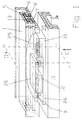
- Fig. 13 shows a window / door with a so-called turn-tilt sash.
- the sash 1 is tiltable about a lower horizontal axis 30 or rotatable about a vertical axis of rotation 31 on the frame 11.
- so-called locking pairs 32 between frame 11 and sash 1 are provided.
- Each of these locking pairings 32 consists of individual locking partners, one of which sits on the frame 11 and the other locking partner on the sash 1.
- either the horizontal tilt axis or the vertical axis of rotation of the window / door is defined. Which of the locking pairings is in engagement is specified by rotating the handle 33 on the sash frame in connection with a known turn-tilt fitting.
- the locking pairings 32 in engagement are formed from a mushroom pin 9 which interacts with an associated entry slot 25 on the other frame part. This is done in that mushroom pin 9 and entry slot 25 are movable relative to each other in the longitudinal direction of the entry slot. The mushroom pin 9 can therefore enter the opening slot 25 from the open side thereof. The mushroom head-like end of the mushroom pin 9 engages behind the entry slot 25 in such a way that the sash 1 is reliably held when trying to pry it open via the tension-proof connection between the mushroom pin 9 and the entry slot 25.
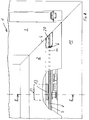
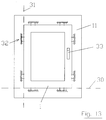
- 1 shows a section of a window / door.
- the entire frame is made of hollow plastic profiles.
- At least the frame 11 additionally shows a metal reinforcement 34 which is continuously inserted into a cavity of the frame 11.
- a so-called striker 10 is attached to the air gap side 35 of the frame 11 and is firmly connected to the frame 11.
- the striker 10 is advantageously screwed with continuous screws against the frame 11, the screws in particular also penetrating the metal reinforcement 34 and in this way firmly anchoring the striker 10 on the frame 11.
- the sash 1 has the hardware groove 5 here.
- the window fitting 6 is inserted in the fitting groove 5.
- Such window fitting 6 consists of a cover rail 7 and a drive rod 8 which slides along the cover rail 7.
- the drive rod 8 is, as is known per se, set in motion via the handle 33 and thereby moved along the cover rail 7.
- the drive rod 8 in turn drives a locking partner 12, which is assigned to the striker 10.
- the locking partner 12 is therefore rigidly connected to the drive rod 8.
- the cover rail 7 has 8 elongated holes 37 in the connection area between the locking partner 12 and the drive rod 8. These elongated holes 37 are from drive rod bolts 36 enforced. In this way, a rigid connection is created between the drive rod 8 and the locking partner 12 on the drive rod, by means of which the locking partner is moved synchronously and in the same direction with the drive rod 8 when the handle 33 is actuated.
- the securing plate 13 which is supported in a suitable manner behind the fitting groove 5 against the sash frame 1, is used here for the additional attachment of the fitting 6 to the sash frame 1. This will be discussed later. At least the securing plate 13 is arranged so that it engages behind the fitting groove 5. It is also essential, however, that depending on the actual installation conditions between sash 1 and frame 11, a securing plate 13 is not absolutely necessary. In any case, the use of the securing plate 13 creates additional security against prying open the sash 1. This will be discussed further.
- At least one of the locking partners 12 with an insertion slot 25 is rigidly connected to the drive rod 8 of the fitting 6.
- This locking partner has an associated mushroom pin 9 on the frame 11. Entry slot 25 and mushroom pin 9 are movable relative to one another in order to allow the mushroom pin with its hat to engage behind the undercut region of the entry slot 25 either in the closed position or in the tilted position.
- the locking partner with the insertion slot must extend over a relatively large length on the fitting, at least the length of the insertion slot 25.
- the locking partner with the insertion slot 25 is connected to the drive rod 8 of the fitting 6, preferably laid flat against the cover rail.
- the large extension length of this locking partner 12 along the cover rail 7 additionally reinforces the fitting 6 in this area, since the locking partner 12 in question is seated on the drive rod 8 and additionally acts as a longitudinal reinforcement of the drive rod 8.
- the fitting 6 is additionally reinforced to be rigid.
- the rear locking plate 13 should also be arranged. This results in a large-scale distribution of the supporting forces from the securing plate 13 to the areas of the sash frame 1 that are gripped behind, so that immense force is necessary to destroy this area of engagement.
- the fitting consisting of drive rod 8 and cover rail 7
- the fitting is held at least in the longitudinal region of the locking partner 12 attached to it with an insertion slot 25 by means of a securing plate 13 engaging behind the fitting groove 5.
- This locking plate 13 engages behind the plastic profile of the casement 1 and is connected in the direction of the frame 11 either with the connecting rod 8 or with the cover rail 7 of the fitting 6.
- the securing plate 13 can be supported in the area behind the sash frame 1, provided that when the sash frame 1 is pried open, the mating mushroom pin insertion slot (9-25) is loaded in the pulling direction.
- the sash frame 1 struck in this way forms a structural unit with the frame 11 that can only be separated under extreme force.
- An essential aspect for the best lever protection is therefore the combination of one or more locking partners 12 with insertion slot 25 on the sash 1 and the arrangement of the locking plate 13 behind it in such a way that the connecting rod 8 and cover rail 7 of the fitting are protected not only by means of the locking plate 13 against being pulled out of the fitting groove, but also largely against due to the flatly attached locking partner 12 with the insertion slot 25 Deflection secured.
- the securing plate 13 can reach behind any area of the casement 1.
- a projection of the fitting groove 5 should be gripped. This offers the advantage that known plastic profiles can be used without any modification.
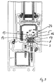
- the entry slot 25 and mushroom pin 9 correspond in that the insertion slot 25 and mushroom pin 9 sit raised on the drive rod 8. They form a so-called first closing part.
- the entry slot 25 and mushroom pin 9 are arranged on a common connecting plate 26.
- the connecting plate 26 lies with its flat back surface 27 close to the counter surface of the adjacent cover rail 7 and is moved together with the drive rod 8 via the drive rod bolts 36 shown in FIG. 3 and already described.
- Entry slot 25 and mushroom pin 9 on the drive rod 8 are assigned a further mushroom pin 9 and an associated entry slot 25 on the frame 11.
- the latter two locking elements sit on a further connecting plate 26 and form the so-called second locking part. Consequently, one of the locking parts is firmly connected to the fitting 6 and the other of the locking parts is fixed to the frame 11.
- the insertion slot 25 and mushroom pin 9 of one locking part (4 of the first locking part on the drive rod) must also be arranged between the insertion slot and the mushroom pin of the other locking part (4 of the second locking part on the frame) and be movable between two end positions. In each of the two end positions, the first locking part on the drive rod engages in the second locking part on the frame.
- An intermediate middle position, shown in Fig. 1,4, is for the first and second Locking part without intervention. In this middle position, the sash 1 can therefore be opened relative to the frame 11.
- the closing part 12, which is connected to the drive rod 8 has a laterally open slot 28 into which the mushroom pin 9, which is rigidly connected to the frame 11, can enter laterally.
- the mushroom pin 9 After the mushroom pin 9 has been retracted to a certain extent into the lateral slot 28, it reaches a longitudinal plane in the associated striker 12. Both sides of the side slot 28 extend in this longitudinal plane to both longitudinal directions of the fitting 6, the insertion slot 25, as described above. If the striker 12, which is connected to the drive rod 8, is in the middle position shown, the sash 1 can therefore be opened or closed with respect to the frame 11. If the sash 1 is closed, the drive rod 8 is then set in motion via the handle 33. The striker 12 is driven accordingly and the associated mushroom pin 9 on the frame 11 can move into the associated entry slot 25.
- FIG. 6 shows that two mushroom bolts are provided, which in turn are arranged on a common connecting plate 26. In this case, only one mushroom bolt acts either for the closed position of the window sash or for the tilt position.
- the side slot 28 must, however, be correspondingly wider.
- This also has the advantage that the striker 12 is attached to the fitting 6 on the casement with a correspondingly larger contact area. Therefore, the fitting 6 is additionally reinforced against deflection.
- a closing part 12 can be attached to the drive rod 8, which has two entry slots 25 which are open at the end.
- a pair of mushroom bolts 9 is rigidly connected to the frame 11.
- One of the mushroom bolts works in the closed position and the other mushroom bolt in the tilted position cooperates with one of the insertion slots.
- Fig. 8 to 12 show a casement, as is known for example for windows or doors.
- sash 1 consists of frame spars 2, 3 which are assembled at right angles in the area of miter points 4.
- frame spars are usually made of plastic profiles, but without restricting the invention to plastic profiles.
- sash frames are also made of wood.
- fitting groove 5 (see FIG. 9) consists of a plastic insert which is screwed tightly to the material of the casement.
- the fitting groove 5 forms a longitudinal material recess on the casement 1.
- the fitting groove 5 has two mutually opposite projections 14, which have the narrowest cross section of the fitting groove 5 define. In the direction of the glass side of the casement, the fitting groove 5 widens behind the projections 14 and thus forms an undercut area.
- the fitting groove 5 serves to receive a window fitting 6.
- a window fitting 6 consists of a cover rail 7 and a drive rod 8 guided longitudinally thereon.
- the cover rail 7 is usually screwed to the base of the fitting groove 5 by means of corresponding elongated holes in the drive rod 8 and held relative to the sash frame.
- so-called mushroom bolts 9 are firmly connected to the drive rod 8. Mushroom bolts can also be provided in pairs (see EP 0 628 691), specifically a mushroom bolt for the closed position and a mushroom bolt for the tilting position of the casement.
- the associated striker 10 has corresponding longitudinal recesses into which the mushroom bolts enter with their stem region, so that the enlarged regions of the mushroom bolts engage behind these insertion slots and thus prevent the sash frame from being levered out.
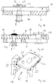
- the cover rail 7 can be fixed in the fitting groove 5 by means of suitable screws. It is specifically provided here as an anti-theft device that the cover rail 7 and drive rod 8 are held on the sash frame by means of a securing plate 13 engaging behind the projection 14 of the fitting groove 5 and that the fitting groove 5 has an entry opening 20 for the securing plate 13 lying outside the holding area 23.
- the securing plate 13 is only provided in the longitudinal region 12 of the locking partner on the drive rod 8.
- the enlarged area 15 of the fitting groove 5 receives the securing plate 13, the width 16 of which is greater than that by the projections 14, the width 15 of the fitting groove 5 is reduced.
- the securing plate 13 rests firmly against the projections 14 and thus prevents the window fitting 6 from being pulled out in the corner area of the window which is sensitive to break-open.
- the securing plate 13 can be firmly connected to the drive rod 8. It then makes the longitudinal movement of the drive rod 8 within the enlarged area 15 of the fitting groove 5 and is for this purpose mounted with play in the longitudinal direction within the fitting groove 5.
- 11 shows that the securing plate 13 is firmly connected to the cover rail 7 by means of bolts 17.
- the bolt 17 breaks through the drive rod 8 in the region of an elongated hole 19, so that the drive rod 8 can move freely from the fastening of the securing plate 13.
- This variant offers the advantage that additional force has to be used to break out the window fitting 6 in order to destroy the cover rail 7 together with the drive rod 8.
- the bolt 17 is mounted with its bolt head 18 in the locking plate 13 in a countersink 24, so that the top of the locking plate 13 is guided in the height direction to the fitting groove with play, which enables smoothness and smoothness.
- FIG. 8 shows that the entry opening 20 for the securing plate 13 is created at the end of the frame spar 2 by a material recess.
- the inlet opening 20 is arranged in the area of the miter point 4, but without restricting the invention. To this The only purpose is to mill the miter area 4 where the hardware grooves of the frame spars 2, 3 meet. The entry opening 20 for the window fitting 6 according to the invention thus inevitably results at the end of the frame spar 2.
- FIG. 12 shows a securing plate 13, which is equipped on two of its opposite longitudinal edges 21 with teeth 22 pointing in the direction of the projection 14. By means of this toothing, the securing plate 13 claws behind the projection 14 when attempting to break open and thus achieves an additional counterforce which counteracts the breaking direction.
- This locking part 12 is rigidly connected to the drive rod 8. It is a component arranged along the drive rod 8. This component has both an insertion slot 25 and an opposite mushroom pin 9.
- the component can be made of chrome-nickel steel or a similar tough material, for example.
- the associated locking part 10 on the frame 11 has a mushroom pin 9 on the side facing the insertion slot 25 of the locking part 12 on the drive rod 8, while the opposite end of the locking part 10 on the frame 11 has one for the mushroom pin 9 on the fitting 6 provided entry slot 25 is provided.
- the associated locking part 12 can be moved on the drive rod 8 such that either the right locking pair, the left Locking pair or no locking pair is engaged.
- a base plate 26 can be used, if necessary, in order to obtain a sufficiently large contact surface on the frame 11.
- the closing part 12 of the drive rod 8 has a central entry slot 25, from which an entry slot 25 coming into engagement with the mushroom pin 9 extends in a longitudinal direction to the drive rod 8.
- Three positions are also provided here: Either the mushroom pin 9 is in engagement with the right entry slot 25, can be freely moved out of the closing part 12 in the middle position, in the left end position with the other entry slot 25. In this way, the closed position, the open position, and the tilted position of the window sash are again realized and nevertheless in the closed position and in the tilted position a tension-proof and lever-proof connection between the sash frame and frame 11.
- FIG. 6 shows, as a further exemplary embodiment, the arrangement of two mushroom bolts 9 on the frame 11.
- the mushroom bolts 9 span a certain distance between them.
- a striker on the fitting or on the drive rod 8 of the fitting can be moved such that this fitting, with its ends open to the outside, is either inserted into one of the mushroom bolts or can be moved out in the central position relative to the mushroom bolts.
- the function of this locking point pairing corresponds to the function described above, if necessary also in combination with a locking plate 13 on the casement frame which engages behind the fitting groove.
- the fastening of the locking parts on the frame 11 can in any case expediently by screwing with the Such windows are usually made of internal metallic reinforcement. Possibly. can also be provided to increase the pull-out security, screws with increased threads. With such screws, the core diameter is significantly smaller in relation to the nominal diameter in order to allow these screws to engage the corresponding reinforcing zone on the metallic reinforcement profile.
- At least one of the locking partners with an entry slot is arranged on the drive rod 8 of the fitting. Since such entry slots require a predetermined length of the associated closing part, namely at least the entry length, the connecting rod 8 of the fitting is disproportionately reinforced in this area against deflection, which means that an extraordinarily high lever protection of the sash frame is achieved with the use of the corresponding engaging locking plate 13.
Landscapes
- Engineering & Computer Science (AREA)
- Mechanical Engineering (AREA)
- Window Of Vehicle (AREA)
- Power-Operated Mechanisms For Wings (AREA)
- Wing Frames And Configurations (AREA)
- Hinges (AREA)
Applications Claiming Priority (2)
| Application Number | Priority Date | Filing Date | Title |
|---|---|---|---|
| DE29513098U DE29513098U1 (de) | 1995-08-16 | 1995-08-16 | Fenster/Tür mit Dreh-Kipp-Beschlag |
| DE29513098U | 1995-08-16 |
Publications (4)
| Publication Number | Publication Date |
|---|---|
| EP0761920A2 true EP0761920A2 (fr) | 1997-03-12 |
| EP0761920A3 EP0761920A3 (fr) | 1997-08-20 |
| EP0761920B1 EP0761920B1 (fr) | 2000-01-05 |
| EP0761920B2 EP0761920B2 (fr) | 2005-05-18 |
Family
ID=8011783
Family Applications (1)
| Application Number | Title | Priority Date | Filing Date |
|---|---|---|---|
| EP96112699A Expired - Lifetime EP0761920B2 (fr) | 1995-08-16 | 1996-08-07 | Fenêtre/porte avec battant pivotant et/ou basculant |
Country Status (4)
| Country | Link |
|---|---|
| EP (1) | EP0761920B2 (fr) |
| AT (1) | ATE188530T1 (fr) |
| DE (2) | DE29513098U1 (fr) |
| DK (1) | DK0761920T3 (fr) |
Cited By (4)
| Publication number | Priority date | Publication date | Assignee | Title |
|---|---|---|---|---|
| DE19625946C2 (de) * | 1996-06-28 | 1998-10-29 | Pax Gmbh | Kombination aus Flügelrahmen und Blendrahmen eines Fensters/einer Tür |
| DE19739407A1 (de) * | 1997-09-09 | 1999-03-11 | Pax Gmbh | Fenster/Tür |
| EP1405974A3 (fr) * | 2002-10-01 | 2004-12-22 | Klaus Dipl.-Ing. Wöppel | Mécanisme de verrouillage pour fenêtre ou porte oscillobattante |
| EP2752307A1 (fr) * | 2013-01-07 | 2014-07-09 | PaX AG | Vitrage pour une porte ou une fenêtre |
Families Citing this family (3)
| Publication number | Priority date | Publication date | Assignee | Title |
|---|---|---|---|---|
| DE19534253A1 (de) * | 1995-09-15 | 1997-03-20 | Pax Gmbh | Fenster/Tür mit Schließstellen zwischen Dreh-Kipp-Flügelrahmen und ortsfestem Blendrahmen |
| EP2476832A3 (fr) * | 2011-01-12 | 2017-06-14 | HAUTAU GmbH | Ferrure à bielle et procédé de fonctionnement pour un chambranle étroit |
| DE102012202151A1 (de) * | 2012-02-13 | 2013-08-14 | Hautau Gmbh | Treibstangenbeschlag mit Spaltlüftungs- und Verriegelungsfunktion |
Family Cites Families (5)
| Publication number | Priority date | Publication date | Assignee | Title |
|---|---|---|---|---|
| DE7838570U1 (de) * | 1978-12-27 | 1979-04-12 | Siegenia-Frank Kg, 5900 Siegen | Fenster, tuer o.dgl. aus kunststoff- profilen |
| DE3329414A1 (de) * | 1983-08-13 | 1985-02-21 | Ulrich 6531 Gensingen Kreusel | Einhand-drehkipp-beschlag fuer ein fenster |
| DE8614557U1 (de) * | 1986-05-30 | 1986-07-17 | Siegenia-Frank Kg, 5900 Siegen | Verhakungsvorrichtung zwischen dem Flügel und dem feststehenden Rahmen von Fenstern, Türen od.dgl. |
| DE4009637C2 (de) * | 1989-07-06 | 1994-04-21 | Saelzer Sicherheitstechnik | Vorrichtung zur Sicherung eines Tür- oder Fensterflügelrahmens |
| DE9308472U1 (de) * | 1993-06-07 | 1993-09-02 | Pax Schweikhard GmbH, 55218 Ingelheim | Dreh-Kipp-Beschlag für Fenster, Türen o.dgl. |
-
1995
- 1995-08-16 DE DE29513098U patent/DE29513098U1/de not_active Expired - Lifetime
-
1996
- 1996-08-07 DE DE59604096T patent/DE59604096D1/de not_active Expired - Lifetime
- 1996-08-07 AT AT96112699T patent/ATE188530T1/de not_active IP Right Cessation
- 1996-08-07 EP EP96112699A patent/EP0761920B2/fr not_active Expired - Lifetime
- 1996-08-07 DK DK96112699T patent/DK0761920T3/da active
Cited By (6)
| Publication number | Priority date | Publication date | Assignee | Title |
|---|---|---|---|---|
| DE19625946C2 (de) * | 1996-06-28 | 1998-10-29 | Pax Gmbh | Kombination aus Flügelrahmen und Blendrahmen eines Fensters/einer Tür |
| DE19739407A1 (de) * | 1997-09-09 | 1999-03-11 | Pax Gmbh | Fenster/Tür |
| EP0902145A2 (fr) | 1997-09-09 | 1999-03-17 | Pax GmbH | Fenêtre ou porte |
| DE19739407C2 (de) * | 1997-09-09 | 2001-05-17 | Pax Gmbh | Fenster/Tür |
| EP1405974A3 (fr) * | 2002-10-01 | 2004-12-22 | Klaus Dipl.-Ing. Wöppel | Mécanisme de verrouillage pour fenêtre ou porte oscillobattante |
| EP2752307A1 (fr) * | 2013-01-07 | 2014-07-09 | PaX AG | Vitrage pour une porte ou une fenêtre |
Also Published As
| Publication number | Publication date |
|---|---|
| EP0761920B2 (fr) | 2005-05-18 |
| DE29513098U1 (de) | 1996-12-19 |
| DK0761920T3 (da) | 2000-05-29 |
| EP0761920A3 (fr) | 1997-08-20 |
| DE59604096D1 (de) | 2000-02-10 |
| EP0761920B1 (fr) | 2000-01-05 |
| ATE188530T1 (de) | 2000-01-15 |
Similar Documents
| Publication | Publication Date | Title |
|---|---|---|
| EP0294630B1 (fr) | Fermeture pour fenêtres, portes, etc. | |
| EP0433623B1 (fr) | Dispositif de verrouillage d'une fenêtre, d'une porte ou similaires | |
| EP0761920B1 (fr) | Fenêtre/porte avec battant pivotant et/ou basculant | |
| EP2113624B1 (fr) | Dispositif de fixation de porte ou de fenêtre | |
| DE19521601C1 (de) | Fenster, Tür oder dergleichen | |
| DE4218983C2 (de) | Fenster, oder Tür mit Beschlägen für den Einbau in abgestufte Profilnuten der Flügel | |
| AT505580B1 (de) | Setzholzfreies fenster, türe oder dgl. | |
| EP3222801A1 (fr) | Verrou pour coffres-forts | |
| EP0844348A1 (fr) | Penture pour portes ou fenêtres | |
| DE9114374U1 (de) | Treibstangenbeschlag für Fenster, Türen o.dgl. | |
| EP0733761B1 (fr) | Cadre de battant | |
| DE4200868A1 (de) | Zusatz-schliesseinrichtung fuer fenster | |
| DE29615631U1 (de) | Sicherungseinrichtung | |
| DE19507481C1 (de) | Abschließbarer Fenstergriff | |
| EP4390027B1 (fr) | Dispositif de levage et de coulissement | |
| DE3215452A1 (de) | Eckumlenkung fuer treibstangenbeschlaege von fenstern, tueren od. dgl. | |
| EP0128372A2 (fr) | Dispositif de fermeture d'un battant d'une porte, fenêtre ou similaire à deux battants | |
| EP0158069B1 (fr) | Dispositif de fermeture et de verrouillage pour une porte ou analogue | |
| DE69705077T2 (de) | Scharnier | |
| WO2025247934A1 (fr) | Ferrure de verrouillage et ensemble porte ou fenêtre | |
| WO2001055541A1 (fr) | Ferrure pour barre d'entrainement | |
| EP0756054A2 (fr) | Fenêtre, porte ou similaire | |
| EP0276379B1 (fr) | Dispositif de fixation pour armatures | |
| DE8901988U1 (de) | Sicherungseinrichtung für Fenster | |
| DE8426285U1 (de) | Schliessplatte fuer fenster- und tuerverschluesse od. dgl. |
Legal Events
| Date | Code | Title | Description |
|---|---|---|---|
| PUAI | Public reference made under article 153(3) epc to a published international application that has entered the european phase |
Free format text: ORIGINAL CODE: 0009012 |
|
| AK | Designated contracting states |
Kind code of ref document: A2 Designated state(s): AT CH DE DK FR GB IT LI SE |
|
| PUAL | Search report despatched |
Free format text: ORIGINAL CODE: 0009013 |
|
| AK | Designated contracting states |
Kind code of ref document: A3 Designated state(s): AT CH DE DK FR GB IT LI SE |
|
| 17P | Request for examination filed |
Effective date: 19971111 |
|
| GRAG | Despatch of communication of intention to grant |
Free format text: ORIGINAL CODE: EPIDOS AGRA |
|
| 17Q | First examination report despatched |
Effective date: 19981123 |
|
| GRAG | Despatch of communication of intention to grant |
Free format text: ORIGINAL CODE: EPIDOS AGRA |
|
| GRAH | Despatch of communication of intention to grant a patent |
Free format text: ORIGINAL CODE: EPIDOS IGRA |
|
| GRAH | Despatch of communication of intention to grant a patent |
Free format text: ORIGINAL CODE: EPIDOS IGRA |
|
| GRAA | (expected) grant |
Free format text: ORIGINAL CODE: 0009210 |
|
| AK | Designated contracting states |
Kind code of ref document: B1 Designated state(s): AT CH DE DK FR GB IT LI SE |
|
| REF | Corresponds to: |
Ref document number: 188530 Country of ref document: AT Date of ref document: 20000115 Kind code of ref document: T |
|
| REG | Reference to a national code |
Ref country code: CH Ref legal event code: NV Representative=s name: E. BLUM & CO. PATENTANWAELTE Ref country code: CH Ref legal event code: EP |
|
| REF | Corresponds to: |
Ref document number: 59604096 Country of ref document: DE Date of ref document: 20000210 |
|
| ITF | It: translation for a ep patent filed | ||
| GBT | Gb: translation of ep patent filed (gb section 77(6)(a)/1977) |
Effective date: 20000307 |
|
| ET | Fr: translation filed | ||
| REG | Reference to a national code |
Ref country code: DK Ref legal event code: T3 |
|
| PGFP | Annual fee paid to national office [announced via postgrant information from national office to epo] |
Ref country code: SE Payment date: 20000807 Year of fee payment: 5 Ref country code: DK Payment date: 20000807 Year of fee payment: 5 |
|
| PGFP | Annual fee paid to national office [announced via postgrant information from national office to epo] |
Ref country code: GB Payment date: 20000809 Year of fee payment: 5 |
|
| PLBI | Opposition filed |
Free format text: ORIGINAL CODE: 0009260 |
|
| PLBQ | Unpublished change to opponent data |
Free format text: ORIGINAL CODE: EPIDOS OPPO |
|
| PLBI | Opposition filed |
Free format text: ORIGINAL CODE: 0009260 |
|
| PLBF | Reply of patent proprietor to notice(s) of opposition |
Free format text: ORIGINAL CODE: EPIDOS OBSO |
|
| 26 | Opposition filed |
Opponent name: SIEGENIA-FRANK KG Effective date: 20000925 |
|
| 26 | Opposition filed |
Opponent name: SCHUECO INTERNATIONAL KG Effective date: 20001004 Opponent name: SIEGENIA-FRANK KG Effective date: 20000925 |
|
| PLBF | Reply of patent proprietor to notice(s) of opposition |
Free format text: ORIGINAL CODE: EPIDOS OBSO |
|
| 29U | Proceedings interrupted after grant according to rule 142 epc |
Effective date: 20010501 |
|
| 29W | Proceedings resumed after grant [after interruption of proceedings according to rule 142 epc] |
Effective date: 20011116 |
|
| PG25 | Lapsed in a contracting state [announced via postgrant information from national office to epo] |
Ref country code: GB Free format text: LAPSE BECAUSE OF NON-PAYMENT OF DUE FEES Effective date: 20010807 Ref country code: DK Free format text: LAPSE BECAUSE OF NON-PAYMENT OF DUE FEES Effective date: 20010807 |
|
| PG25 | Lapsed in a contracting state [announced via postgrant information from national office to epo] |
Ref country code: SE Free format text: LAPSE BECAUSE OF NON-PAYMENT OF DUE FEES Effective date: 20010808 |
|
| PLBF | Reply of patent proprietor to notice(s) of opposition |
Free format text: ORIGINAL CODE: EPIDOS OBSO |
|
| GBPC | Gb: european patent ceased through non-payment of renewal fee |
Effective date: 20010807 |
|
| EUG | Se: european patent has lapsed |
Ref document number: 96112699.2 |
|
| PLBF | Reply of patent proprietor to notice(s) of opposition |
Free format text: ORIGINAL CODE: EPIDOS OBSO |
|
| REG | Reference to a national code |
Ref country code: DK Ref legal event code: EBP |
|
| PLBF | Reply of patent proprietor to notice(s) of opposition |
Free format text: ORIGINAL CODE: EPIDOS OBSO |
|
| PLBF | Reply of patent proprietor to notice(s) of opposition |
Free format text: ORIGINAL CODE: EPIDOS OBSO |
|
| PLAB | Opposition data, opponent's data or that of the opponent's representative modified |
Free format text: ORIGINAL CODE: 0009299OPPO |
|
| R26 | Opposition filed (corrected) |
Opponent name: SCHUECO INTERNATIONAL KG Effective date: 20001004 Opponent name: SIEGENIA-AUBI KG. Effective date: 20000925 |
|
| PGFP | Annual fee paid to national office [announced via postgrant information from national office to epo] |
Ref country code: AT Payment date: 20030813 Year of fee payment: 8 |
|
| PGFP | Annual fee paid to national office [announced via postgrant information from national office to epo] |
Ref country code: FR Payment date: 20030825 Year of fee payment: 8 |
|
| PGFP | Annual fee paid to national office [announced via postgrant information from national office to epo] |
Ref country code: CH Payment date: 20031013 Year of fee payment: 8 |
|
| PG25 | Lapsed in a contracting state [announced via postgrant information from national office to epo] |
Ref country code: AT Free format text: LAPSE BECAUSE OF NON-PAYMENT OF DUE FEES Effective date: 20040807 |
|
| PG25 | Lapsed in a contracting state [announced via postgrant information from national office to epo] |
Ref country code: LI Free format text: LAPSE BECAUSE OF NON-PAYMENT OF DUE FEES Effective date: 20040831 Ref country code: CH Free format text: LAPSE BECAUSE OF NON-PAYMENT OF DUE FEES Effective date: 20040831 |
|
| PUAH | Patent maintained in amended form |
Free format text: ORIGINAL CODE: 0009272 |
|
| STAA | Information on the status of an ep patent application or granted ep patent |
Free format text: STATUS: PATENT MAINTAINED AS AMENDED |
|
| REG | Reference to a national code |
Ref country code: CH Ref legal event code: PL |
|
| PG25 | Lapsed in a contracting state [announced via postgrant information from national office to epo] |
Ref country code: FR Free format text: LAPSE BECAUSE OF NON-PAYMENT OF DUE FEES Effective date: 20050429 |
|
| 27A | Patent maintained in amended form |
Effective date: 20050518 |
|
| AK | Designated contracting states |
Kind code of ref document: B2 Designated state(s): AT CH DE DK FR GB IT LI SE |
|
| REG | Reference to a national code |
Ref country code: FR Ref legal event code: ST |
|
| PG25 | Lapsed in a contracting state [announced via postgrant information from national office to epo] |
Ref country code: IT Free format text: LAPSE BECAUSE OF NON-PAYMENT OF DUE FEES Effective date: 20050807 |
|
| EN | Fr: translation not filed | ||
| PLAB | Opposition data, opponent's data or that of the opponent's representative modified |
Free format text: ORIGINAL CODE: 0009299OPPO |
|
| REG | Reference to a national code |
Ref country code: DE Ref legal event code: R082 Ref document number: 59604096 Country of ref document: DE Representative=s name: MUELLER, JOCHEN, DIPL.-ING., DE Ref country code: DE Ref legal event code: R082 Ref document number: 59604096 Country of ref document: DE Representative=s name: JOCHEN MUELLER, DE |
|
| PGFP | Annual fee paid to national office [announced via postgrant information from national office to epo] |
Ref country code: DE Payment date: 20150820 Year of fee payment: 20 |
|
| REG | Reference to a national code |
Ref country code: DE Ref legal event code: R071 Ref document number: 59604096 Country of ref document: DE |