EP0724079B1 - Injecteur de vapeur - Google Patents
Injecteur de vapeur Download PDFInfo
- Publication number
- EP0724079B1 EP0724079B1 EP95118403A EP95118403A EP0724079B1 EP 0724079 B1 EP0724079 B1 EP 0724079B1 EP 95118403 A EP95118403 A EP 95118403A EP 95118403 A EP95118403 A EP 95118403A EP 0724079 B1 EP0724079 B1 EP 0724079B1
- Authority
- EP
- European Patent Office
- Prior art keywords
- injector
- section
- annular
- mixing chamber
- nozzle
- Prior art date
- Legal status (The legal status is an assumption and is not a legal conclusion. Google has not performed a legal analysis and makes no representation as to the accuracy of the status listed.)
- Expired - Lifetime
Links
- 239000012530 fluid Substances 0.000 claims abstract description 11
- XLYOFNOQVPJJNP-UHFFFAOYSA-N water Substances O XLYOFNOQVPJJNP-UHFFFAOYSA-N 0.000 claims description 71
- 238000010438 heat treatment Methods 0.000 claims description 6
- 238000000034 method Methods 0.000 claims description 3
- 238000010276 construction Methods 0.000 claims 6
- 230000003068 static effect Effects 0.000 claims 3
- 239000007788 liquid Substances 0.000 description 27
- 239000000203 mixture Substances 0.000 description 13
- 238000009833 condensation Methods 0.000 description 9
- 230000005494 condensation Effects 0.000 description 9
- 230000001154 acute effect Effects 0.000 description 5
- 239000003380 propellant Substances 0.000 description 3
- 238000004891 communication Methods 0.000 description 2
- 238000004519 manufacturing process Methods 0.000 description 2
- 230000035508 accumulation Effects 0.000 description 1
- 238000009825 accumulation Methods 0.000 description 1
- 230000015572 biosynthetic process Effects 0.000 description 1
- 238000007664 blowing Methods 0.000 description 1
- 239000003990 capacitor Substances 0.000 description 1
- 230000003247 decreasing effect Effects 0.000 description 1
- 238000006073 displacement reaction Methods 0.000 description 1
- 230000009977 dual effect Effects 0.000 description 1
- 239000011551 heat transfer agent Substances 0.000 description 1
- 239000008236 heating water Substances 0.000 description 1
- 238000002347 injection Methods 0.000 description 1
- 239000007924 injection Substances 0.000 description 1
- 210000004197 pelvis Anatomy 0.000 description 1
- 230000000149 penetrating effect Effects 0.000 description 1
- 230000001105 regulatory effect Effects 0.000 description 1
- 238000010792 warming Methods 0.000 description 1
Images
Classifications
-
- F—MECHANICAL ENGINEERING; LIGHTING; HEATING; WEAPONS; BLASTING
- F22—STEAM GENERATION
- F22D—PREHEATING, OR ACCUMULATING PREHEATED, FEED-WATER FOR STEAM GENERATION; FEED-WATER SUPPLY FOR STEAM GENERATION; CONTROLLING WATER LEVEL FOR STEAM GENERATION; AUXILIARY DEVICES FOR PROMOTING WATER CIRCULATION WITHIN STEAM BOILERS
- F22D1/00—Feed-water heaters, i.e. economisers or like preheaters
- F22D1/28—Feed-water heaters, i.e. economisers or like preheaters for direct heat transfer, e.g. by mixing water and steam
-
- F—MECHANICAL ENGINEERING; LIGHTING; HEATING; WEAPONS; BLASTING
- F04—POSITIVE - DISPLACEMENT MACHINES FOR LIQUIDS; PUMPS FOR LIQUIDS OR ELASTIC FLUIDS
- F04F—PUMPING OF FLUID BY DIRECT CONTACT OF ANOTHER FLUID OR BY USING INERTIA OF FLUID TO BE PUMPED; SIPHONS
- F04F5/00—Jet pumps, i.e. devices in which flow is induced by pressure drop caused by velocity of another fluid flow
- F04F5/14—Jet pumps, i.e. devices in which flow is induced by pressure drop caused by velocity of another fluid flow the inducing fluid being elastic fluid
- F04F5/24—Jet pumps, i.e. devices in which flow is induced by pressure drop caused by velocity of another fluid flow the inducing fluid being elastic fluid displacing liquids, e.g. containing solids, or liquids and elastic fluids
-
- F—MECHANICAL ENGINEERING; LIGHTING; HEATING; WEAPONS; BLASTING
- F28—HEAT EXCHANGE IN GENERAL
- F28C—HEAT-EXCHANGE APPARATUS, NOT PROVIDED FOR IN ANOTHER SUBCLASS, IN WHICH THE HEAT-EXCHANGE MEDIA COME INTO DIRECT CONTACT WITHOUT CHEMICAL INTERACTION
- F28C3/00—Other direct-contact heat-exchange apparatus
- F28C3/06—Other direct-contact heat-exchange apparatus the heat-exchange media being a liquid and a gas or vapour
- F28C3/08—Other direct-contact heat-exchange apparatus the heat-exchange media being a liquid and a gas or vapour with change of state, e.g. absorption, evaporation, condensation
Definitions
- a controllable jet pump is known from DE-OS 23 46 112 known, by means of which two fluids mixed together can be.
- the jet pump has one in one Housing arranged drive current channel, which in a circular blowing nozzle opening opens.
- a rod-operated Adjusting cone arranged by means of which the effective Cross section of the nozzle opening can be varied.
- a catch nozzle is located opposite the driving nozzle opening arranged, which extends away from the driving nozzle Area of constant cross-section and one itself adjoining area with an expanding flow cross-section having. Between the capture nozzle and the An annular suction gap is provided, which is in fluid communication with a suction connection.
- the forms propellant emerging from the propellant nozzle a beam with a circular cross section, which is in the catch nozzle gradually widens. That through the ring-shaped Fluid flowing into the suction gap lies down as a hollow cone Coat around the propellant jet and is from taken away with this.
- a capacitor with one Housing base body known, which is approximately tubular is. At one end is a steam inlet nozzle round, funnel-shaped cross section arranged. Opposite the steam inlet nozzle is one Regulation device arranged that the nozzle more or can release or close less.
- the regulator forms with the inner wall of the tubular Basic body element an annular mixing space.
- the tubular one Basic body Beginning from the suction port is the tubular one Basic body somewhat waisted. With the steam inlet nozzle it forms a somewhat narrowing annular interior, which widens somewhat from the nozzle mouth.
- an injector for introducing a vaporous heat transfer medium into a liquid to be heated with which is the mixture of the heat transfer medium with the one to be heated Liquid and the subsequent condensation of the heat transfer medium allowed without collapse of vapor bubbles.
- this should be made possible in the partial load range.
- the injector has a mixing chamber with an annular one Section in which a mixture of the vaporous Heat transfer medium with the liquid takes place and the vaporous heat transfer medium condenses.
- the vapor bubbles that are formed can be radial Do not exceed the expansion of the mixing chamber in the form of an annular gap, so that the size of those imploding Bubble outgoing pressure surges is limited. So that's it Prerequisite for calm condensation of the vapor Heat transfer medium without knocking.
- the vaporous heat transfer medium becomes through the ring nozzle axially inserted into the mixing chamber, being in the areas creates a suction in front of the outlet opening.
- the steam happens immediately after leaving the ring nozzle has at least one inflow opening, which is preferably as annular opening arranged coaxially to the ring nozzle is designed with a radial opening direction. It sucks the steam from the inflow opening is the liquid to be heated and mixes intensively with it. It has it turned out that by the arrangement of the inflow opening a good one in the immediate vicinity of the ring nozzle Mixing of the vaporous heat transfer medium with the heating liquid is reached.
- the inner wall and the outer wall of the mixing chamber can at least in sections from the ring nozzle define the widening flow cross-section, which creates a speed profile over the length of the mixing chamber is produced. Especially in the areas creates suction at high flow rates, which is used to suck in the liquid to be heated can be.
- the actual mixing area is divided by a section the mixing chamber formed, the outer wall of a tubular part and its inner wall a guide body is formed.
- This, preferably rotationally symmetrical trained guide body can be cylindrical Have section that with the outer wall delimits a hollow cylindrical section of the mixing chamber.
- the flow cross-section is in this actual mixing area constant, due to the condensation of the vaporous heat transfer medium mixed with the liquid the flow velocity over the length of the Mixing chamber can take off.
- An advantageous embodiment that leads to a quiet Condensation and good controllability, has an annularly shaped mixing chamber section on, one length exceeding its outside diameter having. Even at high flow rates here enough distance and therefore enough time for one sufficient, ie complete condensation of the vaporous heat transfer medium in the ring-shaped Section of the mixing chamber available. Following the A hub diffuser can be arranged in the mixing area the flow decelerated.
- Calm condensation is particularly encouraged if the radial thickness of the annular portion is considerable is smaller than the inner diameter of the inner wall. For example, good results are achieved if the radial thickness is less than a fifth of the inside diameter the inner wall is.
- a substantially axial direction of steam flow is erected when the outer diameter of the ring nozzle with the inner diameter of the outer wall of the mixing chamber in essentially coincides.
- a very effective and a constant high flow rate the one to be injected into the liquid vaporous heat transfer medium is achieved when the Ring nozzle for regulating the injector in its flow cross section is designed to be changeable. This can be done easily Can be achieved by using the ring nozzle as an annular gap between the guide body and one in the mixing chamber provided axial bore is limited. If the lead body held axially displaceable and in the area of the ring nozzle is conical, the nozzle cross-section changes with an axial displacement of the guide body.
- the also between the outer tubular mixing chamber and the cylindrical portion of the guide body defined high cylindrical section of the mixing chamber is in its geometry essentially unaffected, whereby also at part load, that is, at lower injected Amount of steam the condensation of the steam calmly and without essential vapor accumulations leading to implosions takes place.
- the regulation of the injector with regard to its Performance thus occurs through a change in Layer thickness of the injected steam.
- Another possibility for the partial load operation of the Injector is given if it has a channel, through which the outflow opening is connected to the inflow opening is. A liquid exchange can take place via this channel take place so that heated liquid from the outflow opening flows to the inflow opening. At this Operating mode, less cold liquid is absorbed, less steam injected and less at the outlet heated liquid dispensed, but the full desired Temperature reached.
- This channel can be annular and the Surround mixing chamber, which makes it simple constructive Relationships.
- the outer wall of the Mixing chamber kept at a relatively high temperature, which are above the ambient temperature and the temperature of the incoming cold liquid to be heated.
- each with a Backflow preventer are equipped.
- This backflow preventer can advantageously in the injector to get integrated.
- the backflow preventer prevent one Backflow of liquid into the ring nozzle and leakage of steam through the inflow opening.
- the injector can be used to heat heating water or of service water.
- the injector increased thereby the pressure of the liquid to be heated through utilization that in the strained gaseous or vaporous Medium contained energy. This makes it possible to Dual function injector for both heating the Use liquid as well as to convey the same.
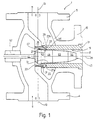
- a steam injector 1 a housing 2 with a connecting flange 4 for steam and a further connection flange 5 for to be heated Liquid, such as cold water.
- the Flange 4 is a steam connection O1 and flange 5 is a cold water connection 03.
- the steam connection O1 and the Cold water connection 03 each lead with a cylindrical Channel 9, 11 in the housing 2, the channel 9 and the channel 11 on a common, the respective opening direction defining central axis 13.
- the housing 2 On the housing 2 is also a right angle to the Flanges 4, 5 vertical third flange 15 provided, which surrounds an outflow opening 17.
- the outflow opening 17 is a circular opening in the housing 2 leading channel, the outer wall 19 of a hollow cylindrical Socket 21 is formed.
- the socket 21 is firmly from a section leading to the flange 15 the housing 2 held and protrudes into one of the Channel 11 formed into the annular space 23, which over the channel 11 with liquid, such as cold water, acted upon is.
- annular space 23 there is an end 25 of the socket 21, in which they both on the inner wall 19, as well their outer walls each have a cylindrical outer surface having.
- the inner outer wall 19 and the outer lateral surfaces are via an end surface 27 connected to each other, following the as the outer wall 19 designated inner circumferential surface an annular Section 27a which is concentric to one defined by the hollow cylindrical bushing 21 Longitudinal central axis 29 is arranged.
- an annular Section 27a which is concentric to one defined by the hollow cylindrical bushing 21 Longitudinal central axis 29 is arranged.
- Radially outwards the end face 27 has one, the circular ring Section 27a adjoining frustoconical Section 27b, which is also concentric with the Longitudinal central axis 29 lies.
- a nozzle body 31 is provided which has a conical opening 33 has.
- the nozzle body 31 is on one on the housing 2 provided and the channel 9 separating from the channel 11 Intermediate wall 35 held the nozzle body 31 in a corresponding opening.
- the nozzle body 31 has a flat surface lying towards the end face 27 37 on, which are spaced and parallel to the annular Section 27a of the end face 27 is arranged and thus defines an annular gap 39 through which the channel 11 communicates with the outflow opening 17.
- a rotationally symmetrical shaped body 43 Via a concentric to the longitudinal central axis 29 lying, held on the housing 2 rod 41 is a rotationally symmetrical shaped body 43 held through the opening 33 of the nozzle body 31 into the bushing 21 extends into it.
- the molded body 43 has a thickened and at least Section 45, which is conical in sections on which is essentially within the channel 9 with the Outflow opening 17 connecting and in the nozzle body 31st provided opening 33 is arranged.
- the frustoconical Section 45 has a lateral surface that with the longitudinal central axis 29 makes an acute angle, which is noticeably less than that between the inner wall the opening 33 and the longitudinal central axis 29 included acute angle. This turns itself into a mouth the opening 33 narrowing annular gap 47 is formed.
- a cylindrical section 49 which extends over the area of the annular gap 39 into the Socket 21 extends into it.
- the diameter of the cylindrical Section 49 is less than the diameter the outer wall 19 of the socket 21, so that the cylindrical Section 49 with the outer wall 19 an annular gap Mixing chamber 51 limited.
- This mixing chamber 51 is hollow their radial thickness is much smaller than their inside diameter is.
- the cylindrical section 49 of the molded body 43 closes a frustoconical section 53 without Paragraph, the length of which is that of the cylindrical portion 49 exceeds and one with the longitudinal central axis 29 shoots in an acute angle. This expands the between the frustoconical section 53 and the Inner wall 19 defined free flow cross section of seen from the annular gap 47.
- the cylindrical section 49 and the frustoconical section 53 delimit in the socket 21 is a mixing chamber with an annular cross section, whose length exceeds their diameter.
- the molded body 43 has a conical end region 55 which forms a hub diffuser and its outer surface an acute angle with the longitudinal central axis 29 includes, which is larger than that of the lateral surface of the frustoconical section 53 with the longitudinal central axis 29 included acute angle.
- the molded body 43 held on the rod 41 is slidable in the housing along the longitudinal central axis 29 2 held.
- the rod 41 is in the wall of the channel 9 penetrating bush 57 stored.
- the longitudinal position of the rod 41 and thus the exact position of the molded body 43 within the nozzle body 31 and the socket 21 is by a with the rod 41st connected, not shown actuator set.
- the actuator can be both hand and motor operated be executed.
- the Drive device can be an element of a control loop, which, for example, a constant water temperature at the To ensure discharge opening 17.
- the injector 1 described so far works as follows:
- the flange 4 is connected to a steam line, via the channel 9 under a constant pressure Steam is supplied.
- the pressure is 1 to 7 bar and is kept constant for the respective application, although it can also be higher.
- the flange 5 is connected to a cold water pipe, the channel 11 under less pressure Cold water supplies, the temperature of which, for example, 14 ° C. is.
- the molded body 43 is off the rod 41 and this acting control element is adjusted so that the annular gap 47 has a sufficient width to the required Allow the amount of steam to pass through.
- the one via the steam connection O1 Incoming steam flows through the from the annular gap 47 formed ring nozzle, its speed is considerable increases. It therefore occurs at high axial speed out of the annular gap 47 and into the mixing chamber 51 a, whereby it is supplied via the cold water connection 03 Cold water is sucked in through the annular gap 39. Mix while doing this the steam and the cold water sucked in intensely with formation of vapor bubbles with relatively little Diameter. The diameter of these vapor bubbles can be Do not exceed the radial thickness of the mixing chamber 51.
- the resulting mixture moves axially through the Mixing chamber 51, wherein the steam condenses and the released heat is transferred to the water.
- the in the mixing chamber 51 at high axial speed moving mixture slows down its axial speed, if it is by the of section 53 or Termination area 55 and the inner wall 9 formed flows through the annular mixing chamber section. No later than when the mixture has passed the termination area 55 is the steam contained in the mixture completely condenses.
- the mixture now has a temperature of, for example. about 90 ° C, the mixture immediately following at the annular gap 47 and 39 on the hub diffuser or Closing area 55 flows along, due to the increasing flow cross section its speed reduced.
- the injector When leaving the injector through the outflow opening 17 it has one opposite at the cold water connection 03 applied water pressure increased pressure.
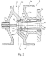
- a modified injector 1a is shown in FIG. 2, this injector 1a as far as it is related same or functionally described with the injector 1 Parts contains the same, for identification purposes is provided with a reference symbol "a". The description given in connection with injector 1 the structure and function is so far on the Transfer injector 1a.
- the injector 1a has a hot water return duct 60 through which the outflow opening 17a with the annular space 23a is in fluid communication.
- the hot water return duct 60 is characterized by a wide, groove-like opening open to the outside Recess 62 in the outer surface of the Socket 21 formed.
- the recess 62 and the corresponding section of the housing 2a enclosed Ring channel opens with a wide and open flow cross-section into the annular space 23a.
- the socket 21a is only with its end lying at the outflow opening 17 connected to the housing 2a, this area with axial bores 64 is provided.
- the steam jet being formed is therefore very thin-walled and only comes with preheated water in contact.
- the developing ones As a result, vapor bubbles are very small and their tendency to implode due to the elevated temperature of the mixture contained water decreased.
- the injector 1a therefore works quietly even in the extreme partial load range and reliable.
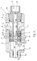
- FIG 3 is a particularly for heating systems illustrated injector 1b intended for residential buildings, the basic structure corresponds to the steam injector 1, but the steam injector 1b also with Check valves 70, 71 provided and in the four-way scheme is constructed. Parts of the injector 1b that with Parts of the injector 1 are functionally the same same reference numerals, being used for identification with ab are provided.
- the flanges 4b, 5b are as Screw flanges or screw connections executed, whereby it does not, as in the case of the injector 1 shown in FIG. 1 opposite, but on opposite sides of the Housing 2b laterally offset from each other are.
- the flange 5b is another communicating with the flange 5b via an annular chamber 72 Screw flange 74 provided another one Cold water connection 02 forms and over the water both can flow in and out. This allows the steam injector 1b of return or cold water can flow through it.
- the annular chamber 72 is provided in the bush 21b Ring groove formed, the width of the diameter of the Flanges 5b, 74 exceeds.
- the socket 21b is at her at the outflow opening 17b side with a Provided external thread, by means of which they are in the housing 2b is held. Between the annular chamber 72 and the external thread there is an O-ring 76 to provide a seal.
- the socket 21b sits in a cylindrical, in which Housing 2b provided receiving space 78, which is the annular chamber 72 limited to the outside. Following the ring chamber 72 the bushing 21b has a radially outwardly extending one Wall 80 on, in the axial openings or Bores 82, 84 are provided which provide a fluid connection create between the annular chamber 72 and the annular space 23b.
- Allowing annular space 23b is one with a central one Hole provided rubber washer 86 provided as a diaphragm valve forms the backflow preventer 71.
- the rubber washer 76 is in one at its radially outer edge corresponding groove of the wall 80 and puts in their In the rest position, the bores 82, 86 close to them on.
- the sleeve 21b abuts an annular, on the Wall 80 provided radial projection 88 on the here disc-shaped nozzle body 31b, the Opening 33b with the shaped body 43 which is cylindrical here Annular gap 47 limited and an annular nozzle for steam forms.
- the molded body 43b is axially immovable with a disc 92 connected in the cylindrical Recording room 78 sits.
- the disk 92 is supported each ring-shaped, in opposite directions axially protruding projections, both on the nozzle body 31b, as well as on a control valve disk 94, the one has conical steam inlet opening 96.
- the disc 92 is with several, on one concentric to the longitudinal central axis 29b lying circle arranged axial bores 98, 100 provided by an edge clamped, the rubber washer 102 forming the backflow preventer 70 are covered.
- the frustoconical and a valve seat Vapor inlet port 96 is axial in sleeve 57b slidable valve member l04 assigned to its, end movable into the steam inlet opening 96 in the shape of a truncated cone trained and there with an O-ring 106 is provided.
- the valve member l04 can be different Assume axial positions, in Figure 3 above the Longitudinal central axis 29b a completely closed valve position and a completely open one below the longitudinal central axis 29b Valve position is shown. When the valve member 104 Intermediate positions is a partial load operation possible.
- the injector 1b essentially consists of rotationally symmetrical ones Share what is manufacturing significantly simplified.
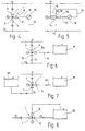
- FIG. 4 schematically shows a heat consumer station shown, the at their steam connection 01 with over a steam line is supplied with steam. Condensate accumulating in the heat consumer station via a condensate manifold forming the cold water connection 02 dissipated.
- the heat consumer station contains essentially a heat consumer 110 that has a Flow line 112 to the flange 15 of the injector 1 connected and supplied with hot water.
- the injector 1 is with its flange 4 to the steam connection 01 connected.
- the flange 5 is connected to a suction line the condensate manifold, to which the Heat consumer 110 connected to a return line 114 is.
- the consumer 110 is any with Industrial consumer heatable water.
- FIG. 5 shows one with hot water operated living space heater 116, which by means of 2 is supplied with hot water.
- the living space heater 116 is via the flow line 112 connected to the flange 15b of the injector 1b while the return line 114 directly to the to a suction port forming flange 5b of the injector 1b is guided.
- the condensate brought in via the return line 114 flows across the injector 1b and is on the screw flange 74 out and into the condensate manifold 02 derived.
- FIG. 6 Another application is shown in Fig. 6, at which a hot water tank 118 by means of the injector 1a Hot water is fed.
- the pelvis is above that at the Flange 15a connected flow line 112 with hot water fed.
- the hot water is mixed by that is called the injection of the steam connection 01 Steam with sucked in from the condensate manifold 02, cooler condensate generated.
- the injector la is included its flange 4a to the steam connection 01 and with its Flange 5a connected to the condensate manifold 02.
- the condensate manifold 02 originating condensate both heated and in the possibly higher-lying hot water pool 118 promoted.
- the injector 1 In the heat consumer station shown in FIG. 7 is the injector 1 with its as a suction connection serving flange 5 connected to a cold water basin 120.
- the flange 4 from the steam connection 01 Steam flowing into the injector conveys from the cold water basin 120 drawn cold water and heats it.
- the hot water generated in this way is under increased pressure ready on the flange 15 and flows over the feed line 112 into the hot water pool 118.
- the injector 1 acts with it as a pump.
- Fig. 8 In the heat consumer station shown in Fig. 8 is by means of the steam injector 1 in one Reservoir 122 kept heated water in the circuit. To is the one with its flange 4 on the steam connection 01 lying injector with its flange 5 so to the reservoir 122 connected to the reservoir 122 water in its Bottom area is removed. The flange 15 leads into the Reservoir 122 back and feeds this with hot water. If steam is applied to the flange 4 of the injector 1, the injector sucks cold water over the flange 5 close to the ground from the reservoir 122 and feeds it with Steam mixing and thereby warming water into the Reservoir 122 back.
Landscapes
- Engineering & Computer Science (AREA)
- Mechanical Engineering (AREA)
- General Engineering & Computer Science (AREA)
- Physics & Mathematics (AREA)
- Thermal Sciences (AREA)
- Fluid Mechanics (AREA)
- Jet Pumps And Other Pumps (AREA)
- Nozzles (AREA)
- Gas Separation By Absorption (AREA)
Claims (25)
- Injecteur (1) pour introduire un caloporteur sous forme de vapeur dans un liquide à réchauffer,caractérisé par le fait queavec une chambre de mélange (51) pourvue d'une ouverture de sortie (17), qui comporte au moins un tronçon conformé en anneau, délimité radialement par une paroi intérieure (49, 53) et une paroi extérieure (19),avec une tuyère (31) alimentée en caloporteur sous forme de vapeur qui débouche dans la chambre de mélange (51),avec au moins une ouverture d'entrée (39) qui peut être alimentée en liquide à réchauffer, débouche dans le tronçon en anneau de la chambre de mélange (51) et, par rapport à la direction d'écoulement définie par la tuyère annulaire (31), est disposée en aval de ladite tuyère annulaire (31),la tuyère (31) présente un ouverture de sortie (47) en forme d'espace annulaire etque l'ouverture d'entrée (39) débouche dans la zone d'aspiration avec une orientation essentiellement radiale de l'ouverture.
- Injecteur selon la revendication 1, caractérisé par le fait que la direction d'écoulement est axiale par rapport à la tuyère annulaire (31).
- Injecteur selon la revendication 1, caractérisé par le fait qu'une zone d'aspiration annulaire dans laquelle débouche l'ouverture d'entrée (39) est formée dans la chambre de mélange (51).
- Injecteur selon la revendication 1, caractérisé par le fait que l'ouverture d'entrée (39) est formée d'un espace annulaire disposé coaxialement avec la tuyère annulaire (31).
- Injecteur selon la revendication 1, caractérisé par le fait que la paroi intérieure (49, 53) et la paroi extérieure (19) définissent une section d'écoulement qui, par tronçons au moins, s'évase dans la direction opposée à la tuyère annulaire (31).
- Injecteur selon la revendication 1, caractérisé par le fait que l'injecteur (1) comporte un élément déflecteur (43) entouré par l'ouverture de sortie en forme d'espace annulaire, qui s'étend dans la direction opposée à celle-ci et qui, à la suite de l'ouverture de sortie (47), forme une paroi intérieure du tronçon annulaire de la chambre de mélange (51).
- Injecteur selon la revendication 6, caractérisé par le fait que la tuyère annulaire qui délimite la chambre de mélange (51) côté frontal, est formée par une ouverture (33) prévue dans un corps de tuyère (31), dans laquelle pénètre l'élément déflecteur (43).
- Injecteur selon la revendication 6, caractérisé par le fait que r l'élément déflecteur (43) comporte un tronçon cylindrique qui s'étend dans un tronçon cylindrique de la chambre de mélange (51).
- Injecteur selon la revendication 1, caractérisé par le fait que l'écoulement dans le tronçon annulaire de la chambre de mélange (51) est axial.
- Injecteur selon la revendication 1, caractérisé par le fait que le tronçon annulaire de la chambre de mélange (51) présente une section d'écoulement constante sur au moins une partie de sa longueur.
- Injecteur selon la revendication 1, caractérisé par le fait que le tronçon annulaire de la chambre de mélange (51) comporte au moins une partie cylindrique creuse.
- Injecteur selon la revendication 1, caractérisé par le fait que la longueur du tronçon annulaire de la chambre de mélange (51) est supérieure ou égale au diamètre extérieur du tronçon et est dimensionnée de telle sorte que la vapeur entrante soit intégralement condensée avant de quitter la zone.
- Injecteur selon la revendication 1, caractérisé par le fait que l'épaisseur radiale du tronçon annulaire de la chambre de mélange (51) est considérablement plus petite que le diamètre extérieur de la paroi intérieure.
- Injecteur selon la revendication 13, caractérisé par le fait que l'épaisseur radiale du tronçon annulaire (51) est au maximum égale à un cinquième dû diamètre extérieur de la paroi intérieure.
- Injecteur selon la revendication 1, caractérisé par le fait que la tuyère annulaire (31) présente une largeur de fente faible par rapport à son diamètre extérieur.
- Injecteur selon la revendication 1, caractérisé par le fait que le diamètre extérieur de l'ouverture formant la tuyère annulaire (31) correspond essentiellement au diamètre intérieur de la paroi extérieure (19) de la chambre de mélange (51).
- Injecteur selon la revendication 1, caractérisé par le fait que la tuyère annulaire (31) est agencée avec une section d'écoulement modifiable.
- Injecteur selon la revendication 1, caractérisé par le fait que l'élément déflecteur (43) est monté mobile de telle sorte que sa longueur de pénétration dans la chambre de mélange (51) soit réglable.
- Injecteur selon la revendication 1, caractérisé par le fait que l'injecteur (1) comporte un canal (60, 62, 64), par l'intermédiaire duquel l'ouverture de sortie (17) est reliée à l'ouverture d'entrée (39).
- Injecteur selon la revendication 19, caractérisé par le fait que le canal (60, 62, 64), par l'intermédiaire duquel l'ouverture de sortie (17) est reliée à l'ouverture d'entrée (39) est annulaire et entoure la chambre de mélange (51).
- Injecteur selon la revendication 1, caractérisé par le fait qu'un moyen (70) empêchant le reflux est placé en amont de la tuyère annulaire (31).
- Injecteur selon la revendication 1, caractérisé par le fait qu'un moyen (71) empêchant le reflux est placé en amont de l'ouverture d'entrée (39).
- Procédé pour l'introduction d'un caloporteur sous forme de vapeur dans un liquide à réchauffer, afin de réchauffer ledit liquide,selon lequel on produit un jet de vapeur de section annulaire qui présente une zone fixe stationnaire à l'intérieur de laquelle la pression statique est minimale etselon lequel le liquide à réchauffer est introduit dans le jet de vapeur présentant une section annulaire, dans la zone de pression statique minimale, dans la direction radiale par rapport au jet de vapeur.
- Procédé selon la revendication 23, caractérisé par le fait que pour régler le réchauffage du liquide, on fait varier la section transversale du jet de vapeur, la pression de repos du caloporteur sous forme de vapeur étant maintenue constante.
- Utilisation de l'injecteur selon la revendication 1, pour introduire de la vapeur d'eau dans de l'eau à réchauffer.
Applications Claiming Priority (2)
| Application Number | Priority Date | Filing Date | Title |
|---|---|---|---|
| DE19502539 | 1995-01-27 | ||
| DE19502539A DE19502539C2 (de) | 1995-01-27 | 1995-01-27 | Dampfinjektor |
Publications (2)
| Publication Number | Publication Date |
|---|---|
| EP0724079A1 EP0724079A1 (fr) | 1996-07-31 |
| EP0724079B1 true EP0724079B1 (fr) | 2000-05-17 |
Family
ID=7752456
Family Applications (1)
| Application Number | Title | Priority Date | Filing Date |
|---|---|---|---|
| EP95118403A Expired - Lifetime EP0724079B1 (fr) | 1995-01-27 | 1995-11-23 | Injecteur de vapeur |
Country Status (3)
| Country | Link |
|---|---|
| EP (1) | EP0724079B1 (fr) |
| AT (1) | ATE193098T1 (fr) |
| DE (2) | DE19502539C2 (fr) |
Families Citing this family (7)
| Publication number | Priority date | Publication date | Assignee | Title |
|---|---|---|---|---|
| DE19719120C2 (de) * | 1997-05-07 | 2000-10-12 | Schneider Bochumer Maschf A | Vorrichtung zur Kühlung von Heißdampf |
| RU2123619C1 (ru) * | 1998-06-25 | 1998-12-20 | Белевич Алексей Игоревич | Парожидкостный струйный аппарат с давлением жидкости на выходе, превышающим давление рабочего газа |
| SE516081C2 (sv) * | 1999-01-26 | 2001-11-12 | Tetra Laval Holdings & Finance | Metod för reglering av en ånginjektor |
| ES2168233T1 (es) * | 1999-12-10 | 2002-06-16 | Zhuhai Velocity Of Sound Techn | Un componente de un sistema de calefaccion. |
| DE102007017704B4 (de) | 2007-04-14 | 2009-12-31 | Gea Tds Gmbh | Injektor und Verfahren zum Einleiten eines dampfförmigen Wärmeträgers in ein flüssiges Produkt |
| DE102013008435A1 (de) * | 2013-05-17 | 2014-11-20 | Herbert Kannegiesser Gmbh | Verfahren und Vorrichtung zum direkten Aufheizen von Flüssigkeiten zur Nassbehandlung von insbesondere Wäschestücken mit Dampf |
| EP3480435B1 (fr) | 2017-11-07 | 2022-03-02 | Volvo Car Corporation | Dispositif de soupape pour un système de rankine |
Family Cites Families (11)
| Publication number | Priority date | Publication date | Assignee | Title |
|---|---|---|---|---|
| DE268934C (fr) * | ||||
| DE407692C (de) * | 1923-08-22 | 1925-01-03 | Actien Ges Der Dillinger Huett | Strahlpumpe |
| US1803054A (en) * | 1926-01-09 | 1931-04-28 | Superheater Co Ltd | Method and apparatus for heating fluids |
| GB612839A (en) * | 1946-05-04 | 1948-11-18 | Spirax Mfg Company Ltd | Improvements in, or relating to, steam-operated heaters for water and other liquids |
| DE924122C (de) * | 1952-01-12 | 1955-02-24 | Huels Chemische Werke Ag | Injektor zur Foerderung von festen, fluessigen, dampf- oder gasfoermigen Stoffen |
| GB790459A (en) * | 1955-07-25 | 1958-02-12 | Schiff And Stern Ges M B H | Improvements in or relating to injector devices |
| GB1397435A (en) * | 1972-08-25 | 1975-06-11 | Hull F R | Regenerative vapour power plant |
| DE2332582A1 (de) * | 1973-06-27 | 1975-01-09 | Holstein & Kappert Maschf | Strahlpumpe, insbesondere zum foerdern und dosieren von fluessigkeiten und gasen |
| DE2342841A1 (de) * | 1973-08-24 | 1975-03-20 | Baelz Gmbh Helmut | Dreiwegeventil, insbesondere fuer warmwasserheizungs- oder -bereitungsanlagen |
| DE2346112A1 (de) * | 1973-09-13 | 1975-03-20 | Baelz Gmbh Helmut | Regelbare strahlpumpe |
| IL74282A0 (en) * | 1985-02-08 | 1985-05-31 | Dan Greenberg | Multishaft jet suction device |
-
1995
- 1995-01-27 DE DE19502539A patent/DE19502539C2/de not_active Expired - Fee Related
- 1995-11-23 AT AT95118403T patent/ATE193098T1/de active
- 1995-11-23 DE DE59508350T patent/DE59508350D1/de not_active Expired - Lifetime
- 1995-11-23 EP EP95118403A patent/EP0724079B1/fr not_active Expired - Lifetime
Also Published As
| Publication number | Publication date |
|---|---|
| ATE193098T1 (de) | 2000-06-15 |
| DE19502539A1 (de) | 1996-08-01 |
| EP0724079A1 (fr) | 1996-07-31 |
| DE59508350D1 (de) | 2000-06-21 |
| DE19502539C2 (de) | 1997-10-02 |
Similar Documents
| Publication | Publication Date | Title |
|---|---|---|
| DE3125583C2 (fr) | ||
| DE1111892B (de) | Wassermischventil | |
| EP0001615A1 (fr) | Dispositif de régulation pour installation de chauffage central | |
| DE19502539C2 (de) | Dampfinjektor | |
| EP1372054B1 (fr) | Vanne de régulation pour un système de circulation d'eau chaude | |
| DE3220050A1 (de) | Verbesserung bei duschsystemen fuer waschzwecke | |
| DE2307084A1 (de) | Ventilbetaetigter dampfwasserableiter | |
| WO2018121811A1 (fr) | Vanne de régulation pour régler la pression différentielle et/ou le débit volumique | |
| DE2839326C2 (de) | Mischventil für sanitäre Anlagen | |
| DE102011107273A1 (de) | Regelventileinrichtung mit Differenzdruckregler | |
| DE3408024A1 (de) | Thermostatregelung | |
| EP3617569A1 (fr) | Armature de raccordement ainsi que système de conduites d'eau | |
| DE8306612U1 (de) | Druckzerstaeuberduese fuer heizungsanlagen | |
| EP0169916B1 (fr) | Pompe, en particulier pompe pour direction assistée | |
| CH400700A (de) | Durchlass-Organ für Hähne, Mischbatterien und dergleichen | |
| EP2979015B1 (fr) | Dispositif à soupapes et appareil de nettoyage à la vapeur | |
| EP4065508B1 (fr) | Pistolet de distribution doté d'un dispositif de protection contre les fuites | |
| DE2330486A1 (de) | Gasbeheizter wassererhitzer, insbesondere durchlauf-wassererhitzer | |
| DE2727225A1 (de) | Axialstrom-drosselorgan | |
| DE102005062592A1 (de) | Einrichtung zum temperaturabhängigen Steuern von Strömungswegen | |
| DE2502349C3 (de) | Wasserarmatur für gasbeheizte Durchlauf-Wassererhitzer | |
| DE2342841A1 (de) | Dreiwegeventil, insbesondere fuer warmwasserheizungs- oder -bereitungsanlagen | |
| DE1782231C (de) | Ventil zum Mischen einer ersten und einer zweiten Flüssigkeit mit einer von außen zugänglichen Durchflußregulier einrichtung | |
| DE19830761C2 (de) | Warm- oder Heißwassererzeuger | |
| DE202017103931U1 (de) | Mischbatterie |
Legal Events
| Date | Code | Title | Description |
|---|---|---|---|
| PUAI | Public reference made under article 153(3) epc to a published international application that has entered the european phase |
Free format text: ORIGINAL CODE: 0009012 |
|
| AK | Designated contracting states |
Kind code of ref document: A1 Designated state(s): AT BE CH DE DK FR GB IT LI LU NL SE |
|
| 17P | Request for examination filed |
Effective date: 19960816 |
|
| 17Q | First examination report despatched |
Effective date: 19990114 |
|
| GRAG | Despatch of communication of intention to grant |
Free format text: ORIGINAL CODE: EPIDOS AGRA |
|
| GRAG | Despatch of communication of intention to grant |
Free format text: ORIGINAL CODE: EPIDOS AGRA |
|
| GRAH | Despatch of communication of intention to grant a patent |
Free format text: ORIGINAL CODE: EPIDOS IGRA |
|
| GRAH | Despatch of communication of intention to grant a patent |
Free format text: ORIGINAL CODE: EPIDOS IGRA |
|
| GRAA | (expected) grant |
Free format text: ORIGINAL CODE: 0009210 |
|
| AK | Designated contracting states |
Kind code of ref document: B1 Designated state(s): AT BE CH DE DK FR GB IT LI LU NL SE |
|
| PG25 | Lapsed in a contracting state [announced via postgrant information from national office to epo] |
Ref country code: NL Free format text: LAPSE BECAUSE OF FAILURE TO SUBMIT A TRANSLATION OF THE DESCRIPTION OR TO PAY THE FEE WITHIN THE PRESCRIBED TIME-LIMIT Effective date: 20000517 Ref country code: IT Free format text: LAPSE BECAUSE OF FAILURE TO SUBMIT A TRANSLATION OF THE DESCRIPTION OR TO PAY THE FEE WITHIN THE PRE;WARNING: LAPSES OF ITALIAN PATENTS WITH EFFECTIVE DATE BEFORE 2007 MAY HAVE OCCURRED AT ANY TIME BEFORE 2007. THE CORRECT EFFECTIVE DATE MAY BE DIFFERENT FROM THE ONE RECORDED.SCRIBED TIME-LIMIT Effective date: 20000517 Ref country code: GB Free format text: LAPSE BECAUSE OF FAILURE TO SUBMIT A TRANSLATION OF THE DESCRIPTION OR TO PAY THE FEE WITHIN THE PRESCRIBED TIME-LIMIT Effective date: 20000517 Ref country code: FR Free format text: LAPSE BECAUSE OF FAILURE TO SUBMIT A TRANSLATION OF THE DESCRIPTION OR TO PAY THE FEE WITHIN THE PRESCRIBED TIME-LIMIT Effective date: 20000517 |
|
| REF | Corresponds to: |
Ref document number: 193098 Country of ref document: AT Date of ref document: 20000615 Kind code of ref document: T |
|
| REG | Reference to a national code |
Ref country code: CH Ref legal event code: EP |
|
| REF | Corresponds to: |
Ref document number: 59508350 Country of ref document: DE Date of ref document: 20000621 |
|
| PG25 | Lapsed in a contracting state [announced via postgrant information from national office to epo] |
Ref country code: SE Free format text: LAPSE BECAUSE OF FAILURE TO SUBMIT A TRANSLATION OF THE DESCRIPTION OR TO PAY THE FEE WITHIN THE PRESCRIBED TIME-LIMIT Effective date: 20000817 Ref country code: DK Free format text: LAPSE BECAUSE OF FAILURE TO SUBMIT A TRANSLATION OF THE DESCRIPTION OR TO PAY THE FEE WITHIN THE PRESCRIBED TIME-LIMIT Effective date: 20000817 |
|
| EN | Fr: translation not filed | ||
| NLV1 | Nl: lapsed or annulled due to failure to fulfill the requirements of art. 29p and 29m of the patents act | ||
| GBV | Gb: ep patent (uk) treated as always having been void in accordance with gb section 77(7)/1977 [no translation filed] |
Effective date: 20000517 |
|
| PG25 | Lapsed in a contracting state [announced via postgrant information from national office to epo] |
Ref country code: LU Free format text: LAPSE BECAUSE OF NON-PAYMENT OF DUE FEES Effective date: 20001123 Ref country code: AT Free format text: LAPSE BECAUSE OF NON-PAYMENT OF DUE FEES Effective date: 20001123 |
|
| PG25 | Lapsed in a contracting state [announced via postgrant information from national office to epo] |
Ref country code: LI Free format text: LAPSE BECAUSE OF NON-PAYMENT OF DUE FEES Effective date: 20001130 Ref country code: CH Free format text: LAPSE BECAUSE OF NON-PAYMENT OF DUE FEES Effective date: 20001130 Ref country code: BE Free format text: LAPSE BECAUSE OF NON-PAYMENT OF DUE FEES Effective date: 20001130 |
|
| PLBE | No opposition filed within time limit |
Free format text: ORIGINAL CODE: 0009261 |
|
| STAA | Information on the status of an ep patent application or granted ep patent |
Free format text: STATUS: NO OPPOSITION FILED WITHIN TIME LIMIT |
|
| 26N | No opposition filed | ||
| BERE | Be: lapsed |
Owner name: HELMUT BALZ G.M.B.H. Effective date: 20001130 |
|
| REG | Reference to a national code |
Ref country code: CH Ref legal event code: PL |
|
| PGFP | Annual fee paid to national office [announced via postgrant information from national office to epo] |
Ref country code: DE Payment date: 20141027 Year of fee payment: 20 |
|
| REG | Reference to a national code |
Ref country code: DE Ref legal event code: R071 Ref document number: 59508350 Country of ref document: DE |