EP0724232B1 - Machine à timbrer et dispositif pour imprimer pour cette machine - Google Patents
Machine à timbrer et dispositif pour imprimer pour cette machine Download PDFInfo
- Publication number
- EP0724232B1 EP0724232B1 EP96300578A EP96300578A EP0724232B1 EP 0724232 B1 EP0724232 B1 EP 0724232B1 EP 96300578 A EP96300578 A EP 96300578A EP 96300578 A EP96300578 A EP 96300578A EP 0724232 B1 EP0724232 B1 EP 0724232B1
- Authority
- EP
- European Patent Office
- Prior art keywords
- ribbon
- spool
- take
- medium
- printing operation
- Prior art date
- Legal status (The legal status is an assumption and is not a legal conclusion. Google has not performed a legal analysis and makes no representation as to the accuracy of the status listed.)
- Expired - Lifetime
Links
- 238000007639 printing Methods 0.000 title claims description 42
- 238000007651 thermal printing Methods 0.000 claims description 21
- 238000000034 method Methods 0.000 claims description 5
- 230000001419 dependent effect Effects 0.000 claims description 4
- 230000001464 adherent effect Effects 0.000 claims 4
- 230000006870 function Effects 0.000 description 4
- 230000015654 memory Effects 0.000 description 3
- 230000002093 peripheral effect Effects 0.000 description 2
- 230000000717 retained effect Effects 0.000 description 2
- 230000005540 biological transmission Effects 0.000 description 1
- 238000010276 construction Methods 0.000 description 1
- 230000007423 decrease Effects 0.000 description 1
- 238000010586 diagram Methods 0.000 description 1
- 230000000694 effects Effects 0.000 description 1
- 238000010438 heat treatment Methods 0.000 description 1
- 238000012544 monitoring process Methods 0.000 description 1
- 239000000758 substrate Substances 0.000 description 1
- 238000011144 upstream manufacturing Methods 0.000 description 1
Images


Classifications
-
- G—PHYSICS
- G07—CHECKING-DEVICES
- G07B—TICKET-ISSUING APPARATUS; FARE-REGISTERING APPARATUS; FRANKING APPARATUS
- G07B17/00—Franking apparatus
- G07B17/00459—Details relating to mailpieces in a franking system
- G07B17/00508—Printing or attaching on mailpieces
-
- G—PHYSICS
- G07—CHECKING-DEVICES
- G07B—TICKET-ISSUING APPARATUS; FARE-REGISTERING APPARATUS; FRANKING APPARATUS
- G07B17/00—Franking apparatus
- G07B17/00185—Details internally of apparatus in a franking system, e.g. franking machine at customer or apparatus at post office
- G07B17/00314—Communication within apparatus, personal computer [PC] system, or server, e.g. between printhead and central unit in a franking machine
-
- G—PHYSICS
- G07—CHECKING-DEVICES
- G07B—TICKET-ISSUING APPARATUS; FARE-REGISTERING APPARATUS; FRANKING APPARATUS
- G07B17/00—Franking apparatus
- G07B17/00185—Details internally of apparatus in a franking system, e.g. franking machine at customer or apparatus at post office
- G07B17/00193—Constructional details of apparatus in a franking system
- G07B2017/0025—Storage of, e.g. ribbon
-
- G—PHYSICS
- G07—CHECKING-DEVICES
- G07B—TICKET-ISSUING APPARATUS; FARE-REGISTERING APPARATUS; FRANKING APPARATUS
- G07B17/00—Franking apparatus
- G07B17/00185—Details internally of apparatus in a franking system, e.g. franking machine at customer or apparatus at post office
- G07B17/00314—Communication within apparatus, personal computer [PC] system, or server, e.g. between printhead and central unit in a franking machine
- G07B2017/00346—Power handling, e.g. power-down routine
-
- G—PHYSICS
- G07—CHECKING-DEVICES
- G07B—TICKET-ISSUING APPARATUS; FARE-REGISTERING APPARATUS; FRANKING APPARATUS
- G07B17/00—Franking apparatus
- G07B17/00459—Details relating to mailpieces in a franking system
- G07B17/00508—Printing or attaching on mailpieces
- G07B2017/00516—Details of printing apparatus
- G07B2017/00524—Printheads
- G07B2017/0054—Thermal printhead
-
- G—PHYSICS
- G07—CHECKING-DEVICES
- G07B—TICKET-ISSUING APPARATUS; FARE-REGISTERING APPARATUS; FRANKING APPARATUS
- G07B17/00—Franking apparatus
- G07B17/00459—Details relating to mailpieces in a franking system
- G07B17/00508—Printing or attaching on mailpieces
- G07B2017/00516—Details of printing apparatus
- G07B2017/00556—Ensuring quality of print
Definitions
- This invention relates to franking machines and to printing means thereof and in particular to thermal printing means in which ink is transferred from a thermal transfer ink ribbon to a print receiving surface of a mail item.
- Franking machines include accounting and control means usually comprising a microprocessor operable to carry out accounting in respect of values of postage charges to be printed on mail item and to decrement a stored value of credit by an amount equal to the value of the postage charge.
- the microprocessor controls operation of feed means to feed the mail item past a print head and at the same time controls the print head to print a franking impression on the mail item, the franking impression including an indication of the value of the postage charge in respect of that mail item.
- the print head has been implemented as a rotatable print drum carrying print dies and print wheels, the print dies being utilised to print an invariable part of the franking impression, and a slogan if desired, and the print wheels being settable to print variable parts of the impression comprising the value of postage charge and date. More recently it has been proposed to used a thermal print head to print the franking impression and slogan.
- the thermal print head includes a plurality of thermal printing elements disposed in a line extending transversely to the direction of feed of the mail item.
- a thermal transfer ink ribbon is interposed between the thermal printing elements and the mail item with an ink layer of the ribbon in contact with the mail item.
- the thermal printing elements are selectively energised by the control means in each of a plurality of printing cycles so as, in each printing cycle, to heat areas of the ink layer to cause transfer of ink from those areas to the mail item to form dots printed at selected positions on the mail item. Repeated selection and energisation of selected thermal printing elements in a series of printing cycles causes printing of dots to form a required printed impression in a line-by-line manner on the mail item.
- the thermal transfer ink ribbon is supplied wound on a spool (supply spool) and is drawn from the supply spool by the feeding of the mail item past the print head due to the adhesion between the ink layer of the ribbon and the mail item. After passing the print head, the used thermal transfer ink ribbon is peeled from the mail item and is wound onto a take-up spool.
- a motor drive is coupled to the take-up spool to rotate the take-up spool so as to wind the ribbon onto the take-up spool and to apply, to the used ribbon downstream of the print head, sufficient tension to the used ribbon to effect peeling of the ribbon from the mail item.
- a printing apparatus according to the preamble of claim 5 is described in EP-A-0315384.
- the present invention provides a method of controlling the take-up of a used thermal transfer ink ribbon in a thermal printing apparatus in which a thermal transfer ink ribbon is drawn from a supply spool, fed together with a print-receiving medium past a thermal print head in a printing operation to form a print impression on the medium, and thereafter the used ribbon is peeled from the medium and wound onto a take-up spool; characterised by the steps, prior to a printing operation, of rotating the take-up spool through a predetermined angle to draw ribbon from the supply spool, determining an extent of resultant rotation of the supply spool, and, in a subsequent printing operation, utilising a function dependent upon the extent of resultant rotation of the supply spool to control energisation of a motor drive for rotation of the take-up spool.
- the present invention provides a printing apparatus, including: a thermal print head; a rotatable supply spool; a rotatable take-up spool; a supply of thermal transfer ink ribbon wound on the supply spool, the ribbon extending from the supply spool past the print head to the take-up spool; means operable, in a printing operation, to bring a print-receiving medium into engagement with the ribbon adjacent the print head, produce relative movement between the medium and the print head, and energise the print head to produce a print impression in a plurality of printing cycles during the movement; a motor drive energisable to rotate the take-up spool to peel the used ribbon from the medium and wind the used ribbon onto the take-up spool; characterised by: control means operable, prior to a printing operation, to energise the motor drive to rotate the take-up spool through a predetermined angle and determine an extent of rotation of the supply spool resulting from the rotation of the
- a franking machine includes a housing and chassis 10 having a feed bed 11 extending horizontally therethrough and in which a first input roller 12, an impression roller 13 and a first ejection roller 14 are mounted.
- the first input roller 12 and impression roller 13 are rotated by means of a first motor 15 through first drive means indicated by broken lines 17 and 18 respectively and the first ejection roller 14 is driven by a second motor 16 through second drive transmission means indicated by broken lines 19.
- the first input roller 12 and the first ejection roller 14 extend through apertures in the feed bed 11 such that the peripheral surfaces of these rollers project slightly above the feed bed so as to engage mail items 20 to be fed along the feed bed 11.
- the input rollers 12 and 21 together form a nip to resiliently engage and receive therebetween the mail item 20 when inserted at entry 22 to the feed bed 11 and to feed the mail item in the direction of arrow 23 into the franking machine along the feed bed 11.
- a second ejection roller 24, which is freely rotatable, is mounted above the first ejection roller 14 and is resiliently urged toward the first ejection roller 14.
- the ejection rollers 14 and 24 together form a nip to resiliently engage and receive therebetween the mail item 20 to eject the mail item through exit 25 from the franking machine.
- a thermal print head 26 is mounted in spaced relationship with the feed bed 11.
- the print head 26 has a plurality of thermal printing elements disposed along a line extending in a direction transverse to the direction indicated by arrow 23 of feeding of the mail item.
- the line of thermal printing elements is parallel to the axis of rotation of the impression roller and the thermal printing elements are disposed in opposition to the peripheral surface of the impression roller 13.
- the impression roller is mounted in a cradle (not shown) whereby the impression roller can be moved by a cradle motor 62 (Fig. 3) into an operative position as shown in Figure 1 from an inoperative position, indicated by broken line 27, and returned to the inoperative position.
- the impression roller In the operative position the impression roller extends through an aperture in the feed bed so as to project from the feed bed and is resiliently urged toward the print head 26.
- the impression roller is retracted to lie below the feed bed 11.
- a thermal transfer ink ribbon is contained in a replaceable cassette 28.
- a supply 29 of unused ribbon is wound on a supply spool 30.
- the unused ribbon 31 extends from the supply spool 30 out of the cassette to pass below the print head 26 and then the used ribbon 32 passes back into the cassette to be wound onto take-up spool 33.
- the ribbon comprises a substrate or backing layer carrying a layer of ink which is transferable from the backing layer to an ink receiving medium. The ribbon is disposed such that the backing layer is adjacent the thermal printing elements of the print head and the ink layer faces the feed bed 11.
- the thermal printing elements are selectively energised in each of a series of printing cycles to heat areas of the ink layer adjacent the selected elements and thereby to cause those areas of the ink layer to adhere more strongly to the surface of the mail item.
- the ribbon After passing the print head, the ribbon is peeled from the mail item leaving those areas of the ink layer which have been subjected to heating by energised ones of the printing elements adhered to the mail item.
- areas of the ink layer are caused to adhere to the mail item to form a required printed impression on the mail item.
- the energisation of the thermal printing elements is controlled by postage metering means such as to print a fixed invariable pattern of a franking impression together with variable data comprising the value of postage charge for the item and the date.
- the ribbon is guided by guide rollers 34, 35 mounted in the cassette and disposed respectively upstream and downstream of the print head. Peeling of the used ribbon from the mail item is effected by applying torque to the take-up spool to wind the used ribbon onto the take-up spool and to apply tension to the ribbon downstream of the thermal print elements.
- the franking machine is provided with a take-up drive hub 37 mounted for rotation on a sub-chassis 38, the sub-chassis 38 being secured to the housing and chassis 10.
- the take-up hub 37 has projections 39 to engage in corresponding recesses in the take-up spool 33 of the cassette to transmit drive from the hub 37 to the take-up spool 33.
- a first gear wheel 40 is secured to and rotatable with the hub 37 and drive is imparted to the gear wheel 40 by means of a second gear wheel 41 secured to a drive shaft of a ribbon take-up stepper motor 42.
- the stepper motor 42 is secured to the sub-chassis 38 by mountings 43.
- the motor Upon energisation of the motor with electrical pulses, the motor rotates in a series of steps and, via the gear wheels 41 and 40, rotates the hub 37 and take-up spool engaged therewith. As described hereinbefore with reference to Figure 1, rotation of the take-up spool causes the used ribbon to be wound onto the take-up spool and tension to be applied to the ribbon so as to peel the used ribbon from the surface of the mail item.
- a further rotatable hub 44 is carried on the sub-chassis 38 and is so located as to engage with the supply spool 30 of the ribbon cassette.
- the hub 44 has projections 45 to engage in corresponding recesses in the supply spool 30 whereby rotation of the supply spool is transmitted to the hub 44.
- a tachometer disc 46 having a plurality of equally spaced slots 47 is secured to the hub 44. Accordingly when the supply spool is rotated due to ribbon being drawn from the supply spool, the tachometer disc is rotated through an angle equal to the angle of rotation of the supply spool.
- Sensing means 48 is mounted on the sub-chassis 38 and is responsive to passage of the slots 47 past the sensing means as the tachometer disc 46 is rotated.
- a micro-processor 50 operating under program routines stored in a read only memory (ROM) 51.
- ROM read only memory
- a keyboard 52 is provided for input of data by a user and a display 53 is provided to enable display of information to the user.
- a random access memory (RAM) 54 is provided for use as a working store for storage of temporary data during operation of the franking machine.
- Non-volatile duplicated memories 55, 56 are provided for the storage of data which is required to be retained even when the franking machine is not powered.
- Accounting data relating to use of the franking machine for printing franking impressions representing postage charges for mail items and any other critical data to be retained is stored in the non-volatile memories 55, 56.
- a motor controller 57 is controlled by the microprocessor 50 to control operation of the motor 15 for driving the input drive roller and the impression roller, to control operation of motor 16 for driving the ejection roller, to control operation of cradle motor 62 to raise and lower the impression roller and to control operation of take-up motor 42 to wind the used ink ribbon 32 onto the take-up spool.
- Sensors 58 are provided to sense and monitor feeding of the mail item along the feed bed 11.
- the sensors provide signals to the microprocessor to enable the microprocessor to control feeding of the mail item and energisation of the thermal print elements as the mail item is fed along past the print head.
- the microprocessor outputs, on line 59, to the print head 26 in each of a plurality of printing cycles signals selecting those ones of the printing elements which are to be energised in the respective cycle.
- a pulse of electrical power is supplied to the selected thermal printing elements from a power source 60 when a strobe signal is supplied by the microprocessor on line 61 to the print head.
- the sensing means 48 for the tachometer disc 46 has an output connected to the microprocessor 50.
- the drive power provided by the stepper motor 42 is of a magnitude such as to provide drive to the take-up spool sufficient to wind the used ribbon onto the take-up spool also to apply sufficient tension to the used ribbon 32 as it passes round the guide roller 35 of the cassette to ensure that the used ribbon is peeled from the mail item.
- the drive power provided by the stepper motor 42 must not be of a magnitude to exert sufficient tension in the ribbon as to cause the ribbon to drawn past the print head faster than the mail item is fed past the print head. If the speed of travel of the ribbon is greater than that of the mail item smudging of the printed impression on the mail item occurs or is likely to occur.
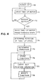
- the franking machine is operated to carry out a routine, illustrated by the flow chart of Figure 4, to determine the number and rate of steps of energisation required for the take-up stepper motor 42.
- step 70 At power up (step 70) of the franking machine the impression roller 13 is in the retracted inoperative position and the ribbon adjacent the print head is unrestrained and free.
- Drive pulses are applied (step 71) to energise the take-up stepper motor 42 to rotate the take-up spool. This rotation of the take-up spool takes up slack in the ribbon between the supply and take up spools.
- a determination (decision box 72) is made as to whether all the slack in the ribbon has been taken up by testing the output of sensing means 48. If no movement of the tachometer disc is detected (NO exit of box 72) the energisation of the take-up motor 42 is continued.
- the sensing means 48 detects movement of the tachometer disc (YES exit of box 72) and hence that the supply spool has been rotated through a small angle due to tension in the ribbon, any slack which was present in the ribbon has been removed.
- the motor 42 is then energised (step 73) with a predetermined number of drive pulses to rotate the take-up spool through a predetermined angle and the resultant angle of rotation of the supply spool is determined (step 74) by monitoring the output of sensing means 48.
- the relationship between the predetermined number of drive pulses and the resultant output of the sensing means 48 is determined (step 75) as a function, for example as a ratio, and is stored (step 76).
- step 77 the mail item is fed by the rollers along the feed bed past the print head and the stored relationship is utilised by control software to determine the number and rate of energisation steps of the take-up motor 42 to peel the used ribbon from the mail item and to wind the used ribbon onto the take-up spool.
- the franking machine may be capable of printing a slogan or other secondary print alongside the franking impression, the secondary print being of predetermined length. Accordingly when a secondary print is printed with the franking impression, the stored relationship is modified to a different extent such as to take into account the overall length of the printed impression comprising the franking impression and the secondary print.
- the take-up spool is rotated by energising the take up motor 42 with pulses and the supply spool rotates as the ribbon is drawn from he supply spool. Accordingly the relationship may be determined continuously or periodically during use of the machine and the current stored value of the relationship is overwritten upon each determination of the relationship.
Landscapes
- Engineering & Computer Science (AREA)
- Physics & Mathematics (AREA)
- General Physics & Mathematics (AREA)
- Computer Security & Cryptography (AREA)
- Computer Hardware Design (AREA)
- General Engineering & Computer Science (AREA)
- Impression-Transfer Materials And Handling Thereof (AREA)
Claims (8)
- Procédé de contrôle de l'enroulement d'un ruban encreur à transfert thermique usé (32) dans un dispositif d'impression thermique dans lequel un ruban encreur à transfert thermique (31) est tiré d'une bobine d'alimentation (29) et entraíné en même temps qu'un support de réception d'impression (20) pour passer devant une tête d'impression thermique (26) dans une opération d'impression, de manière à former une impression sur le support (20), après quoi le ruban usé (32) est détaché du support (20) et enroulé sur une bobine d'enroulement (33),
caractérisé par
les étapes consistant à :faire tourner, avant une opération d'impression, la bobine d'enroulement (33) d'un angle prédéterminé pour tirer le ruban (31) de la bobine d'alimentation (29),déterminer une amplitude de rotation résultante de la bobine d'alimentation (29), etdans une opération d'impression ultérieure, utiliser une fonction dépendant de l'amplitude de la rotation résultante de la bobine d'alimentation (29) pour commander l'alimentation d'un entraínement à moteur (42) destiné à faire tourner la bobine d'enroulement (33). - Procédé selon la revendication 1,
comprenant en outre
avant l'étape consistant à faire tourner la bobine d'enroulement (33) d'un angle prédéterminé, l'étape de rotation de la bobine d'enroulement (33) jusqu'à ce que la rotation résultante de la bobine d'alimentation (29) se produise. - Procédé selon la revendication 1 ou 2,
comprenant en outre
entre une première opération d'impression et une seconde opération d'impression venant après la première opération d'impression, l'étape consistant à modifier la fonction suivant l'amplitude d'alimentation du ruban (31) pendant la première opération d'impression. - Procédé selon l'une quelconque des revendications 1 à 3,
dans lequel l'excitation de l'entraínement à moteur (42) est commandée de manière à appliquer une tension suffisante au ruban utilisé (32) pour qu'elle soit efficace pour détacher le ruban utilisé (32) de son engagement d'adhérence avec le support (20), et inefficace, du fait de l'engagement d'adhérence du ruban (31) avec le support (20) pendant l'opération d'impression, pour produire un mouvement relatif entre le ruban (31) et le support (20). - Dispositif d'impression comprenant :caractérisé parune tête d'impression thermique (26); une bobine d'alimentation rotative (29); une bobine d'enroulement rotative (33); une alimentation de ruban encreur à transfert thermique (31) enroulée sur la bobine d'alimentation (29), le ruban (31) partant de la bobine d'alimentation (29), passant devant la tête d'impression (26) et arrivant à la bobine d'enroulement (33) ; des moyens pouvant être actionnés, dans une opération d'impression, pour amener un milieu ou support de réception d'impression (20) en contact avec le ruban (31) au voisinage de la tête d'impression (26), produire un mouvement relatif entre le support (20) et la tête d'impression (26), et exciter la tête d'impression (26) pour produire une impression dans un certain nombre de cycles d'impression pendant le mouvement ; un entraínement à moteur (42) pouvant être excité pour faire tourner la bobine d'enroulement (33) de façon qu'elle détache le ruban usé (32) du support (20) et enroule ce ruban usé (32) sur la bobine d'enroulement (33) ;
des moyens de commande (50) actionnables, avant une opération d'impression, pour exciter l'entraínement à moteur (42) de façon qu'il fasse tourner la bobine d'enroulement (33) d'un angle prédéterminé et détermine l'amplitude de la rotation de la bobine d'alimentation (29) résultant de la rotation de la bobine d'enroulement (33) d'un angle prédéterminé, ces moyens de commande (50) servant, pendant l'opération d'impression, à commander l'excitation de l'entraínement à moteur (42) suivant une fonction dépendant de l'amplitude de rotation de la bobine d'alimentation (29). - Dispositif d'impression selon la revendication 5,
dans lequel
l'entraínement à moteur (42) comprend un moteur pas à pas excité par des impulsions d'entraínement, et les moyens de commande (50) servent à commander le taux d'application des impulsions d'entraínement à l'entraínement à moteur (42) suivant la fonction voulue. - Dispositif d'impression selon la revendication 5 ou 6,
dans lequel
les moyens de commande (50) servent à commander le taux d'application des impulsions d'entraínement à l'entraínement à moteur (42) suivant la fonction voulue, de manière à appliquer une tension suffisante au ruban usé (32) pour que cette tension soit efficace pour détacher ce ruban usé (32) de son engagement d'adhérence avec le support (20), et soit inefficace, du fait de l'engagement d'adhérence du ruban (31) avec le support (20) pendant l'opération d'impression, pour produire un mouvement relatif entre le ruban (31) et le support (20). - Dispositif d'impression selon l'une quelconque des revendications 5 à 7,
incorporé dans une machine d'affranchissement postal et faisant partie de cette machine.
Applications Claiming Priority (2)
| Application Number | Priority Date | Filing Date | Title |
|---|---|---|---|
| GB9501734 | 1995-01-30 | ||
| GBGB9501734.9A GB9501734D0 (en) | 1995-01-30 | 1995-01-30 | franking apparatus and printing means therefor |
Publications (3)
| Publication Number | Publication Date |
|---|---|
| EP0724232A2 EP0724232A2 (fr) | 1996-07-31 |
| EP0724232A3 EP0724232A3 (fr) | 1998-12-30 |
| EP0724232B1 true EP0724232B1 (fr) | 2002-07-24 |
Family
ID=10768775
Family Applications (1)
| Application Number | Title | Priority Date | Filing Date |
|---|---|---|---|
| EP96300578A Expired - Lifetime EP0724232B1 (fr) | 1995-01-30 | 1996-01-26 | Machine à timbrer et dispositif pour imprimer pour cette machine |
Country Status (4)
| Country | Link |
|---|---|
| US (1) | US6065883A (fr) |
| EP (1) | EP0724232B1 (fr) |
| DE (1) | DE69622444T2 (fr) |
| GB (1) | GB9501734D0 (fr) |
Families Citing this family (10)
| Publication number | Priority date | Publication date | Assignee | Title |
|---|---|---|---|---|
| FR2778869B1 (fr) * | 1998-05-20 | 2000-06-23 | Sagem | Imprimante thermique a ruban encreur pour terminal de traitement de donnees |
| GB0001978D0 (en) * | 2000-01-29 | 2000-03-22 | Neopost Ltd | Method and apparatus for printing on smartcards and the like |
| FR2817987B1 (fr) | 2000-12-13 | 2003-03-28 | Neopost Ind | Systeme de gestion du niveau d'encre pour machine a affranchir |
| FR2817837B1 (fr) | 2000-12-13 | 2003-08-08 | Neopost Ind | Distributeur d'etiquettes en bande |
| US7441970B2 (en) * | 2005-11-10 | 2008-10-28 | Datacard Corporation | Ribbon tensioning mechanisms |
| US9838784B2 (en) | 2009-12-02 | 2017-12-05 | Knowles Electronics, Llc | Directional audio capture |
| US8798290B1 (en) | 2010-04-21 | 2014-08-05 | Audience, Inc. | Systems and methods for adaptive signal equalization |
| US9558755B1 (en) | 2010-05-20 | 2017-01-31 | Knowles Electronics, Llc | Noise suppression assisted automatic speech recognition |
| DE112015004185T5 (de) | 2014-09-12 | 2017-06-01 | Knowles Electronics, Llc | Systeme und Verfahren zur Wiederherstellung von Sprachkomponenten |
| WO2016123560A1 (fr) | 2015-01-30 | 2016-08-04 | Knowles Electronics, Llc | Commutation contextuelle de microphones |
Family Cites Families (7)
| Publication number | Priority date | Publication date | Assignee | Title |
|---|---|---|---|---|
| US4479081A (en) * | 1983-05-13 | 1984-10-23 | General Electric Company | Step motor drive |
| US4788558A (en) * | 1987-02-06 | 1988-11-29 | Intermec Corporation | Method and apparatus for controlling tension in tape progressed along a feed path |
| US4743811A (en) * | 1987-09-21 | 1988-05-10 | Eastman Kodak Company | Adaptive control system for reel to reel web transport apparatus |
| GB8725619D0 (en) * | 1987-11-02 | 1987-12-09 | Roneo Alcatel Ltd | Feed for thermal printing ribbon |
| GB2251216B (en) * | 1990-12-31 | 1995-05-03 | Alcatel Business Systems | Ink ribbon feed |
| CA2078903C (fr) * | 1991-12-13 | 1998-08-18 | Gordon Brent Barrus | Mecanisme d'entrainement de ruban d'imprimante |
| US5318368A (en) * | 1992-09-24 | 1994-06-07 | Pitney Bowes Inc. | Thermal transfer ribbon having ribbon follower |
-
1995
- 1995-01-30 GB GBGB9501734.9A patent/GB9501734D0/en active Pending
-
1996
- 1996-01-26 EP EP96300578A patent/EP0724232B1/fr not_active Expired - Lifetime
- 1996-01-26 DE DE69622444T patent/DE69622444T2/de not_active Expired - Fee Related
-
1998
- 1998-09-02 US US09/145,470 patent/US6065883A/en not_active Expired - Fee Related
Also Published As
| Publication number | Publication date |
|---|---|
| US6065883A (en) | 2000-05-23 |
| GB9501734D0 (en) | 1995-03-22 |
| DE69622444D1 (de) | 2002-08-29 |
| DE69622444T2 (de) | 2003-02-20 |
| EP0724232A3 (fr) | 1998-12-30 |
| EP0724232A2 (fr) | 1996-07-31 |
Similar Documents
| Publication | Publication Date | Title |
|---|---|---|
| US5683190A (en) | Franking apparatus and mail transport thereof | |
| US4924240A (en) | Feed for thermal printing ribbon | |
| EP0253618B1 (fr) | Appareil et procédé d'impression thermique | |
| US5846002A (en) | Method of printing | |
| EP0493942B1 (fr) | Dispositif d'avance pour ruban encreur | |
| EP0724232B1 (fr) | Machine à timbrer et dispositif pour imprimer pour cette machine | |
| CA2106737C (fr) | Reglage de tension de ruban thermique en cassette pour machine a affranchir a impression thermique | |
| EP0434340B1 (fr) | Méthode d'impression à transfert thermique | |
| US5209587A (en) | Ink ribbon feed | |
| US6019526A (en) | Thermal printing apparatus | |
| CA1338694C (fr) | Appareil et methode pour l'impression par transfert thermique | |
| EP0830252A1 (fr) | Procede d'impression | |
| US4899172A (en) | Method and apparatus for perforating indicia on used thermal transfer ribbon within a cassette | |
| EP1125753B1 (fr) | Procédé et dispositif pour imprimer sur cartes à puce et analogues | |
| US4926193A (en) | Thermal transfer ribbon cartridge including ribbon perforating means | |
| GB2297293A (en) | Controlling thermal printing parameters in postage meters in response to coded ink-ribbon cassettes | |
| GB2209137A (en) | Printing of franking on mail items | |
| EP0589715A2 (fr) | Commande de tension de la bande thermique d'une cassette pour une machine d'affranchissement thermique | |
| EP0997309B1 (fr) | Imprimante thermique | |
| GB2202797A (en) | Thermal printing apparatus | |
| EP0478209A2 (fr) | Procédé et dispositif de transmission de données | |
| EP0718106A2 (fr) | Méthode et appareil d'impression | |
| JPH048572A (ja) | 記録装置 |
Legal Events
| Date | Code | Title | Description |
|---|---|---|---|
| PUAI | Public reference made under article 153(3) epc to a published international application that has entered the european phase |
Free format text: ORIGINAL CODE: 0009012 |
|
| AK | Designated contracting states |
Kind code of ref document: A2 Designated state(s): CH DE FR GB LI |
|
| PUAL | Search report despatched |
Free format text: ORIGINAL CODE: 0009013 |
|
| AK | Designated contracting states |
Kind code of ref document: A3 Designated state(s): CH DE FR GB LI |
|
| RHK1 | Main classification (correction) |
Ipc: B41J 2/325 |
|
| 17P | Request for examination filed |
Effective date: 19990628 |
|
| GRAG | Despatch of communication of intention to grant |
Free format text: ORIGINAL CODE: EPIDOS AGRA |
|
| 17Q | First examination report despatched |
Effective date: 20010207 |
|
| GRAG | Despatch of communication of intention to grant |
Free format text: ORIGINAL CODE: EPIDOS AGRA |
|
| GRAG | Despatch of communication of intention to grant |
Free format text: ORIGINAL CODE: EPIDOS AGRA |
|
| GRAG | Despatch of communication of intention to grant |
Free format text: ORIGINAL CODE: EPIDOS AGRA |
|
| GRAH | Despatch of communication of intention to grant a patent |
Free format text: ORIGINAL CODE: EPIDOS IGRA |
|
| GRAH | Despatch of communication of intention to grant a patent |
Free format text: ORIGINAL CODE: EPIDOS IGRA |
|
| GRAA | (expected) grant |
Free format text: ORIGINAL CODE: 0009210 |
|
| AK | Designated contracting states |
Kind code of ref document: B1 Designated state(s): CH DE FR GB LI |
|
| REG | Reference to a national code |
Ref country code: GB Ref legal event code: FG4D |
|
| REG | Reference to a national code |
Ref country code: CH Ref legal event code: EP |
|
| REF | Corresponds to: |
Ref document number: 69622444 Country of ref document: DE Date of ref document: 20020829 |
|
| REG | Reference to a national code |
Ref country code: CH Ref legal event code: NV Representative=s name: HEPP, WENGER & RYFFEL AG |
|
| ET | Fr: translation filed | ||
| PLBE | No opposition filed within time limit |
Free format text: ORIGINAL CODE: 0009261 |
|
| STAA | Information on the status of an ep patent application or granted ep patent |
Free format text: STATUS: NO OPPOSITION FILED WITHIN TIME LIMIT |
|
| 26N | No opposition filed |
Effective date: 20030425 |
|
| PGFP | Annual fee paid to national office [announced via postgrant information from national office to epo] |
Ref country code: DE Payment date: 20090122 Year of fee payment: 14 |
|
| PGFP | Annual fee paid to national office [announced via postgrant information from national office to epo] |
Ref country code: GB Payment date: 20090122 Year of fee payment: 14 Ref country code: CH Payment date: 20090115 Year of fee payment: 14 |
|
| PGFP | Annual fee paid to national office [announced via postgrant information from national office to epo] |
Ref country code: FR Payment date: 20090115 Year of fee payment: 14 |
|
| REG | Reference to a national code |
Ref country code: CH Ref legal event code: PL |
|
| GBPC | Gb: european patent ceased through non-payment of renewal fee |
Effective date: 20100126 |
|
| REG | Reference to a national code |
Ref country code: FR Ref legal event code: ST Effective date: 20100930 |
|
| PG25 | Lapsed in a contracting state [announced via postgrant information from national office to epo] |
Ref country code: LI Free format text: LAPSE BECAUSE OF NON-PAYMENT OF DUE FEES Effective date: 20100131 Ref country code: FR Free format text: LAPSE BECAUSE OF NON-PAYMENT OF DUE FEES Effective date: 20100201 Ref country code: CH Free format text: LAPSE BECAUSE OF NON-PAYMENT OF DUE FEES Effective date: 20100131 |
|
| PG25 | Lapsed in a contracting state [announced via postgrant information from national office to epo] |
Ref country code: DE Free format text: LAPSE BECAUSE OF NON-PAYMENT OF DUE FEES Effective date: 20100803 |
|
| PG25 | Lapsed in a contracting state [announced via postgrant information from national office to epo] |
Ref country code: GB Free format text: LAPSE BECAUSE OF NON-PAYMENT OF DUE FEES Effective date: 20100126 |