EP0724274A2 - Supraleitende Anordnung zur Fehlerstrombegrenzung - Google Patents
Supraleitende Anordnung zur Fehlerstrombegrenzung Download PDFInfo
- Publication number
- EP0724274A2 EP0724274A2 EP96300289A EP96300289A EP0724274A2 EP 0724274 A2 EP0724274 A2 EP 0724274A2 EP 96300289 A EP96300289 A EP 96300289A EP 96300289 A EP96300289 A EP 96300289A EP 0724274 A2 EP0724274 A2 EP 0724274A2
- Authority
- EP
- European Patent Office
- Prior art keywords
- superconductive
- fault
- current limiter
- primary
- limiter according
- Prior art date
- Legal status (The legal status is an assumption and is not a legal conclusion. Google has not performed a legal analysis and makes no representation as to the accuracy of the status listed.)
- Granted
Links
Images
Classifications
-
- H—ELECTRICITY
- H02—GENERATION; CONVERSION OR DISTRIBUTION OF ELECTRIC POWER
- H02H—EMERGENCY PROTECTIVE CIRCUIT ARRANGEMENTS
- H02H9/00—Emergency protective circuit arrangements for limiting excess current or voltage without disconnection
- H02H9/02—Emergency protective circuit arrangements for limiting excess current or voltage without disconnection responsive to excess current
- H02H9/023—Current limitation using superconducting elements
-
- H—ELECTRICITY
- H01—ELECTRIC ELEMENTS
- H01F—MAGNETS; INDUCTANCES; TRANSFORMERS; SELECTION OF MATERIALS FOR THEIR MAGNETIC PROPERTIES
- H01F6/00—Superconducting magnets; Superconducting coils
- H01F6/06—Coils, e.g. winding, insulating, terminating or casing arrangements therefor
-
- H—ELECTRICITY
- H01—ELECTRIC ELEMENTS
- H01F—MAGNETS; INDUCTANCES; TRANSFORMERS; SELECTION OF MATERIALS FOR THEIR MAGNETIC PROPERTIES
- H01F6/00—Superconducting magnets; Superconducting coils
- H01F2006/001—Constructive details of inductive current limiters
-
- Y—GENERAL TAGGING OF NEW TECHNOLOGICAL DEVELOPMENTS; GENERAL TAGGING OF CROSS-SECTIONAL TECHNOLOGIES SPANNING OVER SEVERAL SECTIONS OF THE IPC; TECHNICAL SUBJECTS COVERED BY FORMER USPC CROSS-REFERENCE ART COLLECTIONS [XRACs] AND DIGESTS
- Y02—TECHNOLOGIES OR APPLICATIONS FOR MITIGATION OR ADAPTATION AGAINST CLIMATE CHANGE
- Y02E—REDUCTION OF GREENHOUSE GAS [GHG] EMISSIONS, RELATED TO ENERGY GENERATION, TRANSMISSION OR DISTRIBUTION
- Y02E40/00—Technologies for an efficient electrical power generation, transmission or distribution
- Y02E40/60—Superconducting electric elements or equipment; Power systems integrating superconducting elements or equipment
Definitions
- This invention relates to superconductive fault-current limiters (SCFCL).
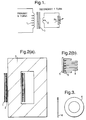
- an inductive SCFCL may be represented by a primary winding 1 and shorted secondary winding 2 wound around an iron (or air) core 3.
- the shorted winding is a layer or cylinder of superconductor material and the primary winding forms part of a circuit which is to be protected against fault currents.
- the shorted winding is a layer or cylinder of superconductor material and the primary winding forms part of a circuit which is to be protected against fault currents.
- the shorted winding is a layer or cylinder of superconductor material and the primary winding forms part of a circuit which is to be protected against fault currents.
- induced current in the superconductor effectively shields (or cancels) the magnetic flux of the primary winding from the iron core and a low inductance is presented by the SCFCL to the circuit.
- the current density in the superconductor rises above a critical value the superconductor becomes resistive and the induced superconductor current fails to produce a sufficient, balancing
- the resistance R S in the secondary circuit of Figure 1 represents the superconductor resistance that arises when the primary current exceeds the fault current.
- a superconductive fault-current limiter of the inductive type using so-called high temperature superconductor (HTS), is known, for example from European Patent No. 0353449.
- HTS high temperature superconductor
- a problem that arises in prior art devices such as mentioned above is that the fault current that can be accommodated is unduly limited by the cross sectional area of the superconductive flow path.
- An attempt to increase the fault current threshold by increasing the thickness of the secondary cylinder (and thus the cross section of the flow path) in the prior art device is unsatisfactory because the critical current density of the superconductor (J C ) deteriorates as the thickness increases.
- a thin layer of HTS is desirable to ensure short switching times and to ensure that temperature rise during fault conditions remains controllable without the need to activate circuit breakers in the circuit being protected.
- the superconductive cylinder comprises a substrate coated with superconductive material, the substrate being of such form that at least sections of the superconductive coating extend laterally relative to the axis of the cylinder.
- At least some of said sections may be exposed surfaces permitting cooling fluid to contact the superconductive coating.
- the substrate may comprise a stack of individual washer-like components coated with superconductive material on one or both faces.
- the washer-like components may be interleaved with spacing members to permit cooling fluid to contact the superconductive coatings.
- the substrate may be a cylinder having a grooved outer surface.
- the substrate may be of substantially uniform thickness and of corrugated form.
- the superconductive cylinder and the primary winding may be disposed at the same location on the ferromagnetic circuit and the superconductive cylinder lie within the primary winding.
- a primary winding 1 is connected in series in a circuit to be protected.
- the winding 1 embraces a ferromagnetic core 3 which is also coupled to a superconductive winding 2 constituting a short circuited secondary.
- the resistance of the secondary winding is represented by a variable resistor R s , the value depending upon the superconductive state. This in turn depends upon the current density, being superconductive below a critical value J c and resistive above that value. In the superconducting state at normal current values, the current induced in the superconductive cylinder is such that the ampere-turns are equal and opposite to that of the primary winding.
- the two windings may then be considered in combination to produce a net zero field intensity and consequently a net zero flux in the iron core.
- the superconductive cylinder 2 acts as a screen to prevent the primary flux from 'seeing' the iron core.
- the primary inductance is thus very low and there is negligible impedance presented to the protected circuit.
- the secondary current rises with the primary current until the critical current, I c for the superconducting screen is exceeded.
- the secondary becomes resistive (i.e. R s increases from zero)
- the two magnetic intensities go out of balance
- a net flux enters the iron core
- the primary winding inductance increases greatly and the resulting increased impedance limits the fault current.
- this shows a rectangular soft iron core 3 one limb of which is embraced by a primary copper winding 1 and a superconductive cylinder 2 constituting a short-circuited secondary winding.
- the cylinder 2 is only broadly of cylindrical form and consists of a ceramic tube 5 of zirconia (shown enlarged in Figure 2(b)) fitted with washer-like pieces 4, see Figure 3, of zirconia, the latter being coated on one or both sides with a high temperature superconductor.
- a ceramic tube 5 of zirconia shown enlarged in Figure 2(b)
- washer-like pieces 4 see Figure 3, of zirconia, the latter being coated on one or both sides with a high temperature superconductor.
- HTS materials are available having a critical temperature above 77°K.
- the washers 4 are spaced apart by circular spacers 6 also of ceramic.
- the coating thickness is in the range 50-100 ⁇ m and is limited to 100 ⁇ m to avoid deterioration of J c.
- the radial extent of the coated surface of the washer may be of the order of 50-100 times the coating thickness.
- the spacers may be of similar size and shape to the coated washers so as to produce, in effect a solid, thick walled, ceramic cylinder having periodic superconductive annular sections.
- the temperature be kept below the critical temperature.
- leakage flux may escape between the annular sections so permitting a degree of coupling between primary flux and the iron core. This can be overcome by controlling the spacing between washers and/or by coating the tubular substrate (5) itself with a thick film of superconductive material. No gaps would then be available for the escape of leakage flux.
- This arrangement is preferable so as to gain the benefit of the screening effect, enhanced as necessary by coating the tubular substrate 5.
- the superconductive cylinder provides no screen effect but in combination with the primary copper winding produces a net zero external flux. There can however be a degree of flux leakage from the primary winding which will couple with the adjacent iron core despite the balancing superconductive winding.
- the primary and secondary 'windings' may be displaced around the magnetic circuit so that they embrace different limbs of the core.
- superior results have been obtained where the windings are located together, and with the superconductive winding inside the copper winding.
- the increased cross section of the secondary current flow path can be obtained by the use of superconductive coatings of form different from that used in the washer arrangement.
- the surface of the ceramic cylinder could be given a serpentine or zig-zag contour in the plane of Figure 2 by cutting V-grooves in the surface.
- a thin-walled ceramic cylinder could be moulded with corrugations of circular or other section and the corrugated surface coated with superconductive material on one or both sides this would achieve the increased cross section and at the same time permit efficient cooling.
- the superconductive material could be coated on to a corrugated metallic cylinder if the metallic cylinder were of high enough resistance.
- the described embodiments effectively increase the superconductive coating cross section by increasing its length (within the same overall length dimension) without increasing its thickness.
- the design criterion for shielding flux density B p is that the total amp turns per metre in the superconductor are equal and opposite to the amp turns per metre in the primary windings.
- B p is exceeded part or all of the flux enters the iron core.
- the present status of HTS coated on to substrate material is that the J c value deteriorates as the thickness of the layer is increased.
- a thin layer of HTS is required to ensure short switching times and also to ensure that temperature rise during fault conditions remains controllable without the need to activate a protective circuit-breaker in order to prevent burn-out.
- J c t value of 2 x 10 4 Am -1 or more is required for a film thickness of 50-100 ⁇ m. Consequently, J c 's of 5 x 10 9 - 1 x 10 10 Am -2 are sought . At present J c values of this magnitude in HTS material at 77K are only possible for thin films ( ⁇ 1 ⁇ m).
- the invention provides a method by which the desired product, J c t can be effectively achieved whilst at the same time preserving the requirement for a film thickness ⁇ 100 ⁇ m.
- the design described above with relation to Figure 2 employs direct cooling by the circulation of a liquid gas between the washers 4.
- a cold gas cryocooler is employed.
- a heat shunt is placed in close contact with the washer to be cooled and the end of the heat shunt remote from the washer is cooled by a cold gas - helium for example.
- the heat shunt may be in the form of a washer acting as a spacer between the superconductor coated washers 4. This heat shunt preferably extends radially beyond the washers 4 to provide good access for the coolant gas.
- Suitable materials for the heat shunt are alumina, ruby or diamond which all have good thermal conductivity and poor electrical conductivity
Landscapes
- Engineering & Computer Science (AREA)
- Power Engineering (AREA)
- Emergency Protection Circuit Devices (AREA)
- Superconductors And Manufacturing Methods Therefor (AREA)
- Containers, Films, And Cooling For Superconductive Devices (AREA)
Applications Claiming Priority (2)
| Application Number | Priority Date | Filing Date | Title |
|---|---|---|---|
| GB9501717A GB2297432A (en) | 1995-01-28 | 1995-01-28 | Superconductive fault current limiters |
| GB9501717 | 1995-01-28 |
Publications (3)
| Publication Number | Publication Date |
|---|---|
| EP0724274A2 true EP0724274A2 (de) | 1996-07-31 |
| EP0724274A3 EP0724274A3 (de) | 1996-10-16 |
| EP0724274B1 EP0724274B1 (de) | 2000-09-13 |
Family
ID=10768761
Family Applications (1)
| Application Number | Title | Priority Date | Filing Date |
|---|---|---|---|
| EP96300289A Expired - Lifetime EP0724274B1 (de) | 1995-01-28 | 1996-01-16 | Supraleitende Anordnung zur Fehlerstrombegrenzung |
Country Status (6)
| Country | Link |
|---|---|
| US (1) | US5694279A (de) |
| EP (1) | EP0724274B1 (de) |
| CN (1) | CN1054710C (de) |
| AT (1) | ATE196382T1 (de) |
| DE (1) | DE69610229T2 (de) |
| GB (1) | GB2297432A (de) |
Cited By (7)
| Publication number | Priority date | Publication date | Assignee | Title |
|---|---|---|---|---|
| WO1998043335A1 (en) * | 1997-03-06 | 1998-10-01 | Nkt Research Center A/S | A current limiter with a superconducting current limiting element |
| EP1320166A1 (de) * | 2001-12-12 | 2003-06-18 | Abb Research Ltd. | Vorrichtung der Supraleitungstechnik |
| WO2012168317A1 (de) * | 2011-06-08 | 2012-12-13 | Schneider Electric Sachsenwerk Gmbh | Vorrichtung zur strombegrenzung |
| EP2672537A1 (de) * | 2012-06-06 | 2013-12-11 | Bruker HTS GmbH | Supraleitervorrichtung ohne externes Shuntsystem, insbesondere mit einer Ringform |
| WO2016135311A1 (de) * | 2015-02-27 | 2016-09-01 | Siemens Aktiengesellschaft | Elektrische spuleneinrichtung zur induktiv-resistiven strombegrenzung |
| WO2017097351A1 (de) * | 2015-12-09 | 2017-06-15 | Siemens Aktiengesellschaft | Hochenergie-stossstrombegrenzer |
| DE102016223022A1 (de) | 2016-09-23 | 2018-03-29 | Siemens Aktiengesellschaft | Induktiver Strombegrenzer für Gleichstromanwendungen |
Families Citing this family (17)
| Publication number | Priority date | Publication date | Assignee | Title |
|---|---|---|---|---|
| GB9621142D0 (en) * | 1996-10-10 | 1996-11-27 | Oxford Instr Public Limited Co | Current limiting device |
| GB2321137B (en) * | 1997-01-11 | 2000-11-15 | Gec Alsthom Ltd | Electric power transfer means |
| US6275365B1 (en) | 1998-02-09 | 2001-08-14 | American Superconductor Corporation | Resistive fault current limiter |
| DE19827227A1 (de) * | 1998-06-18 | 1999-12-23 | Siemens Ag | Strombegrenzungseinrichtung mit Leiterbahnanordnung aus Hoch-T¶c¶-Supraleitermaterial sowie Verfahren zur Herstellung der Einrichtung |
| US6751075B2 (en) * | 2001-12-12 | 2004-06-15 | The University Of Chicago | Superconducting fault current controller/current controller |
| US6920027B1 (en) * | 2002-11-12 | 2005-07-19 | Felix Torres | Fast, variable, and reliable power system controller design |
| US7023673B2 (en) * | 2002-12-23 | 2006-04-04 | The University Of Chicago | Superconducting shielded core reactor with reduced AC losses |
| EP1524748B1 (de) * | 2003-10-15 | 2008-02-27 | Nexans | Supraleitender Strombegrenzer mit magnetfeldunterstütztem Quench |
| US7440244B2 (en) * | 2005-04-02 | 2008-10-21 | Superpower, Inc. | Self-triggering superconducting fault current limiter |
| EP1830446B1 (de) * | 2006-01-13 | 2008-12-10 | European High Temperature Superconductors GmbH & Co. KG | Strombegrenzer |
| US8588875B2 (en) * | 2010-01-21 | 2013-11-19 | Superpower, Inc. | Superconducting fault current-limiter with variable shunt impedance |
| US8739396B2 (en) * | 2010-06-17 | 2014-06-03 | Varian Semiconductor Equipment Associates, Inc. | Technique for limiting transmission of fault current |
| EP2402961B1 (de) * | 2010-07-02 | 2013-12-04 | Bruker HTS GmbH | Verfahren zur Stromregelung, insbesondere bei einem Fehlerstrombegrenzer |
| US9754716B2 (en) * | 2011-08-01 | 2017-09-05 | General Electric Technology Gmbh | Current limiter |
| DE102012218260B3 (de) | 2012-10-05 | 2013-12-05 | Bruker Hts Gmbh | Induktiver Fehlerstrombegrenzer mit geteilter Sekundärspulenanordnung |
| DE102012218261B3 (de) | 2012-10-05 | 2013-11-14 | Bruker Hts Gmbh | Induktiver Fehlerstrombegrenzer mit geteilter Primärspulenanordnung |
| KR101470965B1 (ko) * | 2013-08-30 | 2014-12-10 | 연세대학교 산학협력단 | 직류 리액터의 역자화 구조 및 이의 초전도 벌크를 이용한 역자화 방법 |
Family Cites Families (11)
| Publication number | Priority date | Publication date | Assignee | Title |
|---|---|---|---|---|
| FR1370673A (fr) * | 1963-06-24 | 1964-08-28 | Csf | Bobine à enroulement supraconducteur et son procédé de fabrication |
| BE657518A (de) * | 1963-12-30 | 1965-06-23 | ||
| DE1489856A1 (de) * | 1965-11-13 | 1969-05-14 | Eder Dr Ing Franz X | Supraleitungsspule |
| JPS5732607A (en) * | 1980-08-05 | 1982-02-22 | Japan Atom Energy Res Inst | Superconductive coil |
| US4431980A (en) * | 1980-10-08 | 1984-02-14 | Hitachi, Ltd. | Electrical apparatus winding |
| JPS5958803A (ja) * | 1982-09-28 | 1984-04-04 | Fujikura Ltd | 超電導コイルの製造方法 |
| JPS63119507A (ja) * | 1986-11-07 | 1988-05-24 | Sumitomo Electric Ind Ltd | 超電導マグネツト |
| CH677549A5 (de) * | 1988-08-02 | 1991-05-31 | Asea Brown Boveri | |
| US5173678A (en) * | 1990-09-10 | 1992-12-22 | Gte Laboratories Incorporated | Formed-to-shape superconducting coil |
| US5241447A (en) * | 1991-02-27 | 1993-08-31 | The United States Of America As Represented By The Secretary Of The Air Force | Magnetic switch structure and method employing superconductive material |
| DE69401722T2 (de) * | 1993-03-26 | 1997-07-03 | Ngk Insulators Ltd | Supraleitende Anordnung zur Fehlerstrombegrenzung |
-
1995
- 1995-01-28 GB GB9501717A patent/GB2297432A/en not_active Withdrawn
-
1996
- 1996-01-11 US US08/584,735 patent/US5694279A/en not_active Expired - Fee Related
- 1996-01-16 EP EP96300289A patent/EP0724274B1/de not_active Expired - Lifetime
- 1996-01-16 DE DE69610229T patent/DE69610229T2/de not_active Expired - Fee Related
- 1996-01-16 AT AT96300289T patent/ATE196382T1/de not_active IP Right Cessation
- 1996-01-26 CN CN96102552A patent/CN1054710C/zh not_active Expired - Fee Related
Cited By (7)
| Publication number | Priority date | Publication date | Assignee | Title |
|---|---|---|---|---|
| WO1998043335A1 (en) * | 1997-03-06 | 1998-10-01 | Nkt Research Center A/S | A current limiter with a superconducting current limiting element |
| EP1320166A1 (de) * | 2001-12-12 | 2003-06-18 | Abb Research Ltd. | Vorrichtung der Supraleitungstechnik |
| WO2012168317A1 (de) * | 2011-06-08 | 2012-12-13 | Schneider Electric Sachsenwerk Gmbh | Vorrichtung zur strombegrenzung |
| EP2672537A1 (de) * | 2012-06-06 | 2013-12-11 | Bruker HTS GmbH | Supraleitervorrichtung ohne externes Shuntsystem, insbesondere mit einer Ringform |
| WO2016135311A1 (de) * | 2015-02-27 | 2016-09-01 | Siemens Aktiengesellschaft | Elektrische spuleneinrichtung zur induktiv-resistiven strombegrenzung |
| WO2017097351A1 (de) * | 2015-12-09 | 2017-06-15 | Siemens Aktiengesellschaft | Hochenergie-stossstrombegrenzer |
| DE102016223022A1 (de) | 2016-09-23 | 2018-03-29 | Siemens Aktiengesellschaft | Induktiver Strombegrenzer für Gleichstromanwendungen |
Also Published As
| Publication number | Publication date |
|---|---|
| EP0724274A3 (de) | 1996-10-16 |
| ATE196382T1 (de) | 2000-09-15 |
| CN1054710C (zh) | 2000-07-19 |
| GB9501717D0 (en) | 1995-03-15 |
| GB2297432A (en) | 1996-07-31 |
| US5694279A (en) | 1997-12-02 |
| CN1137698A (zh) | 1996-12-11 |
| DE69610229T2 (de) | 2001-04-26 |
| DE69610229D1 (de) | 2000-10-19 |
| EP0724274B1 (de) | 2000-09-13 |
Similar Documents
| Publication | Publication Date | Title |
|---|---|---|
| EP0724274B1 (de) | Supraleitende Anordnung zur Fehlerstrombegrenzung | |
| EP0620570B1 (de) | Supraleitende Anordnung zur Fehlerstrombegrenzung | |
| US5379020A (en) | High-temperature superconductor and its use | |
| US5892644A (en) | Passive fault current limiting device | |
| CA1331206C (en) | Fault current limiter | |
| EP0620630A1 (de) | Supraleitende Anordnung zur Fehlerstrombegrenzung | |
| EP0935261B1 (de) | Resistiver Fehlerstrombegrenzer | |
| US7180396B2 (en) | Superconducting current limiting device with magnetic field assisted quenching | |
| US4910626A (en) | Current limiter | |
| US4812796A (en) | Quench propagation device for a superconducting magnet | |
| US4727346A (en) | Superconductor and normally conductive spaced parallel connected windings | |
| DE19524579C2 (de) | Transformator als Strombegrenzer | |
| US20030191028A1 (en) | Superconducting device with inductive current limiter using a high-tc superconducting material | |
| US6344956B1 (en) | Oxide bulk superconducting current limiting element current | |
| US5334964A (en) | Current limiting choke coil | |
| US5355275A (en) | Current limiting device for electromagnetic coil employing gap containing superconductive shield | |
| US20110034337A1 (en) | Superconductive current limiter with magnetic field triggering | |
| US20060268471A1 (en) | Resistive superconducting fault current limiter | |
| EP3553839B1 (de) | Supraleitender fehlerstrombegrenzer | |
| US3102973A (en) | Superconducting device | |
| JP2607822B2 (ja) | 超電導限流器 | |
| US20040120083A1 (en) | Superconducting shielded core reactor with reduced AC losses | |
| JPH06314625A (ja) | 超電導限流器 | |
| JPH09172206A (ja) | 超電導限流器 | |
| JPH07272960A (ja) | 超電導限流器 |
Legal Events
| Date | Code | Title | Description |
|---|---|---|---|
| PUAI | Public reference made under article 153(3) epc to a published international application that has entered the european phase |
Free format text: ORIGINAL CODE: 0009012 |
|
| AK | Designated contracting states |
Kind code of ref document: A2 Designated state(s): AT BE CH DE ES FR GB IT LI NL PT SE |
|
| PUAL | Search report despatched |
Free format text: ORIGINAL CODE: 0009013 |
|
| AK | Designated contracting states |
Kind code of ref document: A3 Designated state(s): AT BE CH DE ES FR GB IT LI NL PT SE |
|
| 17P | Request for examination filed |
Effective date: 19970415 |
|
| RAP1 | Party data changed (applicant data changed or rights of an application transferred) |
Owner name: ALSTOM UK LTD |
|
| GRAG | Despatch of communication of intention to grant |
Free format text: ORIGINAL CODE: EPIDOS AGRA |
|
| GRAG | Despatch of communication of intention to grant |
Free format text: ORIGINAL CODE: EPIDOS AGRA |
|
| 17Q | First examination report despatched |
Effective date: 19990512 |
|
| GRAG | Despatch of communication of intention to grant |
Free format text: ORIGINAL CODE: EPIDOS AGRA |
|
| GRAH | Despatch of communication of intention to grant a patent |
Free format text: ORIGINAL CODE: EPIDOS IGRA |
|
| GRAH | Despatch of communication of intention to grant a patent |
Free format text: ORIGINAL CODE: EPIDOS IGRA |
|
| GRAA | (expected) grant |
Free format text: ORIGINAL CODE: 0009210 |
|
| AK | Designated contracting states |
Kind code of ref document: B1 Designated state(s): AT BE CH DE ES FR GB IT LI NL PT SE |
|
| PG25 | Lapsed in a contracting state [announced via postgrant information from national office to epo] |
Ref country code: NL Free format text: LAPSE BECAUSE OF FAILURE TO SUBMIT A TRANSLATION OF THE DESCRIPTION OR TO PAY THE FEE WITHIN THE PRESCRIBED TIME-LIMIT Effective date: 20000913 Ref country code: LI Free format text: LAPSE BECAUSE OF FAILURE TO SUBMIT A TRANSLATION OF THE DESCRIPTION OR TO PAY THE FEE WITHIN THE PRESCRIBED TIME-LIMIT Effective date: 20000913 Ref country code: IT Free format text: LAPSE BECAUSE OF FAILURE TO SUBMIT A TRANSLATION OF THE DESCRIPTION OR TO PAY THE FEE WITHIN THE PRE;WARNING: LAPSES OF ITALIAN PATENTS WITH EFFECTIVE DATE BEFORE 2007 MAY HAVE OCCURRED AT ANY TIME BEFORE 2007. THE CORRECT EFFECTIVE DATE MAY BE DIFFERENT FROM THE ONE RECORDED.SCRIBED TIME-LIMIT Effective date: 20000913 Ref country code: ES Free format text: THE PATENT HAS BEEN ANNULLED BY A DECISION OF A NATIONAL AUTHORITY Effective date: 20000913 Ref country code: CH Free format text: LAPSE BECAUSE OF FAILURE TO SUBMIT A TRANSLATION OF THE DESCRIPTION OR TO PAY THE FEE WITHIN THE PRESCRIBED TIME-LIMIT Effective date: 20000913 Ref country code: BE Free format text: LAPSE BECAUSE OF FAILURE TO SUBMIT A TRANSLATION OF THE DESCRIPTION OR TO PAY THE FEE WITHIN THE PRESCRIBED TIME-LIMIT Effective date: 20000913 |
|
| REF | Corresponds to: |
Ref document number: 196382 Country of ref document: AT Date of ref document: 20000915 Kind code of ref document: T |
|
| REG | Reference to a national code |
Ref country code: CH Ref legal event code: EP |
|
| REF | Corresponds to: |
Ref document number: 69610229 Country of ref document: DE Date of ref document: 20001019 |
|
| PG25 | Lapsed in a contracting state [announced via postgrant information from national office to epo] |
Ref country code: PT Free format text: LAPSE BECAUSE OF FAILURE TO SUBMIT A TRANSLATION OF THE DESCRIPTION OR TO PAY THE FEE WITHIN THE PRESCRIBED TIME-LIMIT Effective date: 20001213 |
|
| ET | Fr: translation filed | ||
| NLV1 | Nl: lapsed or annulled due to failure to fulfill the requirements of art. 29p and 29m of the patents act | ||
| REG | Reference to a national code |
Ref country code: CH Ref legal event code: PL |
|
| PLBE | No opposition filed within time limit |
Free format text: ORIGINAL CODE: 0009261 |
|
| STAA | Information on the status of an ep patent application or granted ep patent |
Free format text: STATUS: NO OPPOSITION FILED WITHIN TIME LIMIT |
|
| 26N | No opposition filed | ||
| REG | Reference to a national code |
Ref country code: GB Ref legal event code: IF02 |
|
| PGFP | Annual fee paid to national office [announced via postgrant information from national office to epo] |
Ref country code: AT Payment date: 20031204 Year of fee payment: 9 |
|
| PGFP | Annual fee paid to national office [announced via postgrant information from national office to epo] |
Ref country code: FR Payment date: 20031208 Year of fee payment: 9 |
|
| PGFP | Annual fee paid to national office [announced via postgrant information from national office to epo] |
Ref country code: GB Payment date: 20031211 Year of fee payment: 9 |
|
| PGFP | Annual fee paid to national office [announced via postgrant information from national office to epo] |
Ref country code: DE Payment date: 20031212 Year of fee payment: 9 |
|
| PGFP | Annual fee paid to national office [announced via postgrant information from national office to epo] |
Ref country code: SE Payment date: 20031218 Year of fee payment: 9 |
|
| PG25 | Lapsed in a contracting state [announced via postgrant information from national office to epo] |
Ref country code: GB Free format text: LAPSE BECAUSE OF NON-PAYMENT OF DUE FEES Effective date: 20050116 Ref country code: AT Free format text: LAPSE BECAUSE OF NON-PAYMENT OF DUE FEES Effective date: 20050116 |
|
| PG25 | Lapsed in a contracting state [announced via postgrant information from national office to epo] |
Ref country code: SE Free format text: LAPSE BECAUSE OF NON-PAYMENT OF DUE FEES Effective date: 20050117 |
|
| PG25 | Lapsed in a contracting state [announced via postgrant information from national office to epo] |
Ref country code: DE Free format text: LAPSE BECAUSE OF NON-PAYMENT OF DUE FEES Effective date: 20050802 |
|
| EUG | Se: european patent has lapsed | ||
| GBPC | Gb: european patent ceased through non-payment of renewal fee |
Effective date: 20050116 |
|
| PG25 | Lapsed in a contracting state [announced via postgrant information from national office to epo] |
Ref country code: FR Free format text: LAPSE BECAUSE OF NON-PAYMENT OF DUE FEES Effective date: 20050930 |
|
| REG | Reference to a national code |
Ref country code: FR Ref legal event code: ST |