EP0935261B1 - Resistiver Fehlerstrombegrenzer - Google Patents
Resistiver Fehlerstrombegrenzer Download PDFInfo
- Publication number
- EP0935261B1 EP0935261B1 EP99300920A EP99300920A EP0935261B1 EP 0935261 B1 EP0935261 B1 EP 0935261B1 EP 99300920 A EP99300920 A EP 99300920A EP 99300920 A EP99300920 A EP 99300920A EP 0935261 B1 EP0935261 B1 EP 0935261B1
- Authority
- EP
- European Patent Office
- Prior art keywords
- coil
- superconducting
- fault current
- longitudinal axis
- conductive
- Prior art date
- Legal status (The legal status is an assumption and is not a legal conclusion. Google has not performed a legal analysis and makes no representation as to the accuracy of the status listed.)
- Revoked
Links
- 235000012771 pancakes Nutrition 0.000 claims description 55
- 238000004804 winding Methods 0.000 claims description 36
- 239000000463 material Substances 0.000 claims description 33
- 239000004020 conductor Substances 0.000 claims description 19
- 239000002887 superconductor Substances 0.000 claims description 17
- 238000000034 method Methods 0.000 claims description 16
- 239000002131 composite material Substances 0.000 claims description 7
- 230000000712 assembly Effects 0.000 claims description 5
- 238000000429 assembly Methods 0.000 claims description 5
- 230000005540 biological transmission Effects 0.000 description 10
- 238000013459 approach Methods 0.000 description 8
- 229910052782 aluminium Inorganic materials 0.000 description 4
- XAGFODPZIPBFFR-UHFFFAOYSA-N aluminium Chemical compound [Al] XAGFODPZIPBFFR-UHFFFAOYSA-N 0.000 description 4
- 238000009826 distribution Methods 0.000 description 4
- 238000010276 construction Methods 0.000 description 3
- 239000010949 copper Substances 0.000 description 3
- 230000004907 flux Effects 0.000 description 3
- 238000009413 insulation Methods 0.000 description 3
- RYGMFSIKBFXOCR-UHFFFAOYSA-N Copper Chemical compound [Cu] RYGMFSIKBFXOCR-UHFFFAOYSA-N 0.000 description 2
- 239000005751 Copper oxide Substances 0.000 description 2
- 230000004323 axial length Effects 0.000 description 2
- 239000011248 coating agent Substances 0.000 description 2
- 238000000576 coating method Methods 0.000 description 2
- 229910052802 copper Inorganic materials 0.000 description 2
- 229910000431 copper oxide Inorganic materials 0.000 description 2
- 229960004643 cupric oxide Drugs 0.000 description 2
- 230000001965 increasing effect Effects 0.000 description 2
- 239000007788 liquid Substances 0.000 description 2
- 238000004519 manufacturing process Methods 0.000 description 2
- 239000011159 matrix material Substances 0.000 description 2
- 230000007704 transition Effects 0.000 description 2
- 241000070918 Cima Species 0.000 description 1
- QPLDLSVMHZLSFG-UHFFFAOYSA-N Copper oxide Chemical compound [Cu]=O QPLDLSVMHZLSFG-UHFFFAOYSA-N 0.000 description 1
- 239000004593 Epoxy Substances 0.000 description 1
- 239000004952 Polyamide Substances 0.000 description 1
- 229910000831 Steel Inorganic materials 0.000 description 1
- 239000000919 ceramic Substances 0.000 description 1
- 238000001816 cooling Methods 0.000 description 1
- 230000000694 effects Effects 0.000 description 1
- 239000011521 glass Substances 0.000 description 1
- 230000001939 inductive effect Effects 0.000 description 1
- 238000002955 isolation Methods 0.000 description 1
- 229910052751 metal Inorganic materials 0.000 description 1
- 239000002184 metal Substances 0.000 description 1
- 229910000510 noble metal Inorganic materials 0.000 description 1
- 239000004033 plastic Substances 0.000 description 1
- 229920002647 polyamide Polymers 0.000 description 1
- 238000010248 power generation Methods 0.000 description 1
- 239000002243 precursor Substances 0.000 description 1
- 238000002360 preparation method Methods 0.000 description 1
- 230000001681 protective effect Effects 0.000 description 1
- 229910052594 sapphire Inorganic materials 0.000 description 1
- 239000010980 sapphire Substances 0.000 description 1
- 229910052709 silver Inorganic materials 0.000 description 1
- 239000004332 silver Substances 0.000 description 1
- 229910001220 stainless steel Inorganic materials 0.000 description 1
- 239000010935 stainless steel Substances 0.000 description 1
- 239000010959 steel Substances 0.000 description 1
- 239000013589 supplement Substances 0.000 description 1
- 229910021521 yttrium barium copper oxide Inorganic materials 0.000 description 1
Images


Classifications
-
- H—ELECTRICITY
- H10—SEMICONDUCTOR DEVICES; ELECTRIC SOLID-STATE DEVICES NOT OTHERWISE PROVIDED FOR
- H10N—ELECTRIC SOLID-STATE DEVICES NOT OTHERWISE PROVIDED FOR
- H10N60/00—Superconducting devices
- H10N60/30—Devices switchable between superconducting and normal states
-
- H—ELECTRICITY
- H01—ELECTRIC ELEMENTS
- H01F—MAGNETS; INDUCTANCES; TRANSFORMERS; SELECTION OF MATERIALS FOR THEIR MAGNETIC PROPERTIES
- H01F6/00—Superconducting magnets; Superconducting coils
- H01F6/06—Coils, e.g. winding, insulating, terminating or casing arrangements therefor
-
- H—ELECTRICITY
- H02—GENERATION; CONVERSION OR DISTRIBUTION OF ELECTRIC POWER
- H02H—EMERGENCY PROTECTIVE CIRCUIT ARRANGEMENTS
- H02H9/00—Emergency protective circuit arrangements for limiting excess current or voltage without disconnection
- H02H9/02—Emergency protective circuit arrangements for limiting excess current or voltage without disconnection responsive to excess current
- H02H9/023—Current limitation using superconducting elements
-
- H—ELECTRICITY
- H01—ELECTRIC ELEMENTS
- H01F—MAGNETS; INDUCTANCES; TRANSFORMERS; SELECTION OF MATERIALS FOR THEIR MAGNETIC PROPERTIES
- H01F6/00—Superconducting magnets; Superconducting coils
- H01F2006/001—Constructive details of inductive current limiters
-
- Y—GENERAL TAGGING OF NEW TECHNOLOGICAL DEVELOPMENTS; GENERAL TAGGING OF CROSS-SECTIONAL TECHNOLOGIES SPANNING OVER SEVERAL SECTIONS OF THE IPC; TECHNICAL SUBJECTS COVERED BY FORMER USPC CROSS-REFERENCE ART COLLECTIONS [XRACs] AND DIGESTS
- Y02—TECHNOLOGIES OR APPLICATIONS FOR MITIGATION OR ADAPTATION AGAINST CLIMATE CHANGE
- Y02E—REDUCTION OF GREENHOUSE GAS [GHG] EMISSIONS, RELATED TO ENERGY GENERATION, TRANSMISSION OR DISTRIBUTION
- Y02E40/00—Technologies for an efficient electrical power generation, transmission or distribution
- Y02E40/60—Superconducting electric elements or equipment; Power systems integrating superconducting elements or equipment
Definitions
- This invention relates to fault current limiters.
- Fault currents are large (usually temporary) increases in the normal current flowing in a power transmission system.
- a fault current can occur from any number of different events including lightning strikes or catastrophic failure of electrical equipment which can cause short circuits.
- a short circuit for example, can cause a twenty-fold or more increase in current flow to the circuit.
- circuit breakers are used in virtually every power transmission and distribution system to "open" the circuit and interrupt current flow in the event of a fault.
- the fault current level grows as new equipment is added over time.
- the control circuit processes the signal and then generates a control signal to the circuit breaker to open.
- steps which may have a duration as long as 100 msec
- the circuit breaker, as well as other parts of the transmission system are subjected to the higher fault current level.
- the circuit breaker, transformers, as well as other components of the system are often rated to withstand, for a period of time the higher current levels.
- Fault current limiters were developed to insert impedance in a connection quickly so as limit the magnitude of the fault current to a reduced level, thereby protecting the circuit breaker and the power transmission system.
- Many fault current limiters include tuned reactance circuits which store energy in proportion to the circuit inductance.
- a superconducting current limiting device is constructed using a heat dissipating wafer (e.g., sapphire) having a thin coating of superconducting material deposited onto a surface of the wafer.
- a heat dissipating wafer e.g., sapphire
- the coating transitions into its normal state and becomes resistive, thereby limiting the flow of current until a circuit breaker, in parallel with the device, interrupts the current flow.
- a resistive superconducting solenoid is connected within a bridge circuit of diodes or thyristors.
- current flows through forward-biased pairs of the diodes, bypassing the superconducting solenoid.
- the diodes or thyristors become reversed-biased causing the current to flow through the resistive superconducting solenoid.
- bulk superconducting rods or rings are used to limit the level of fault currents.
- EP-A-0503447 discloses a plurality of superconductive current limiters each in the form of a bifilar coil, formed in a stack and connected together in series.
- a coil assembly having a longitudinal axis, the coil assembly comprising a plurality of bifilar pancake coils disposed in a stack arrangement along the longitudinal axis, each coil including a pair of conductive winding sections joined along an innermost radial region of the coil, wound together, one over the other, radially outward and around the longitudinal axis, characterised in that each pancake coil is electrically connected to an adjacent pancake coil so that current flowing in adjacent turns of adjacent pancake coils flows in opposite directions at all radial regions of the coil assembly.
- a fault current limiting coil having a longitudinal axis comprising:
- the invention features a superconducting fault current limiter configured as a coil assembly to provide a minimized inductance and low resistance in a normal state of operation. When a fault current exceeds a predetermined threshold, the resistance increases to a level sufficient for limiting the flow of fault current.
- the coil assembly includes adjacent bifilar pancake coil electrically connected so that current flowing in adjacent turns of the adjacent pancake coils flows in opposite directions.
- the bifilar pancake coils are disposed in a stack arrangement along the longitudinal axis.
- Each coil includes a pair of conductive winding sections joined along an innermost radial region of the coil, wound together, one over the other, radially outward and around the longitudinal axis.
- Magnetic coils are generally constructed to provide a large inductive component in a relatively compact space.
- This coil arrangement provides a coil which minimizes the total inductance while providing a required resistance when current flowing through the coil exceeds a threshold value, all within a compact space.
- the coil arrangement includes a pair of parallel wound, bifilar windings so that current in one segment of the winding flows in a direction opposite to that of an adjacent segment of the winding. Because the currents flow in opposite directions, magnetic flux and inductance induced by these currents are minimized.
- a relatively compact superconducting fault current limiter with minimum inductance and high resistance in its non-superconducting state is provided.
- two or more of the coil assemblies are positioned on a support structure to provide a fault current limiter assembly.
- a method of providing a coil includes electrically connecting adjacent pancake coils so that current flowing in adjacent turns of adjacent pancake coils flows in opposite directions.
- Embodiments of the above aspects of the invention may include one or more of the following features.
- the winding sections are each formed from an integral piece of conductive material provided in bifilar fashion.
- a second pair of conductive windings joined along an innermost radial region of the coil i.e., a second bifilar winding
- the conductive winding is formed of a superconducting material (e.g., high or low temperature superconductor).
- a superconducting material e.g., high or low temperature superconductor
- the material is anisotropic and is in the form of a superconducting tape.
- the anisotropic superconducting material is a multi-filament composite conductor including multiple superconducting filaments enclosed in matrix-forming material.
- the superconducting material is not anisotropic and is a monolithic superconductor material.
- the fault current limiters have numerous applications including bus-tie and co-generation applications.
- the superconducting fault current limiter also provides a level of isolation between neighboring power utility transmission and distribution networks, permitting them to be connected together while minimizing the risk that a fault occurring on one will affect the other.
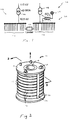
- a bus network 100 of a portion of an electrical power system includes a pair of sub-networks 102, 104 each having an associated transformer 106, 108 for stepping-down a high voltage (e.g., 110 KV) from the power grid to a lower distribution voltage (e.g., 10.5 KV).
- Each of sub-networks 102, 104 provide electrical power to a smaller geographical region (e.g., industrial complex, residential area) via power transmission lines 110.
- a limiter 112 ties sub-networks 102, 104 together so that either sub-network can provide or supplement power to the other in the event of a failure (e.g., failed transformer).
- Sub-network 104 also includes a superconducting fault current limiter 10 connected between the output of transformer 108 and a connection point 114 which, for example, leads to another portion of bus network 100 or to another power generation source.
- Superconducting fault current limiter 10 is housed in a cryostat (thermal container) and is cryogenically cooled.
- fault current limiter 10 limits the amount of current flowing therethrough to a predetermined threshold level typically 3 to 5 times of the normal level in the event of catastrophic electrical failure such as a short circuit. Fault current limiter 10 limits the current for a period sufficient (about 0.5 seconds) to allow a circuit breaker (not shown) to interrupt current flow and prevent damage to the components connected to and within bus network 100. In the application shown in Fig. 1, in essence, fault current limiter 10 serves to isolate bus network 100 from connection point 114.
- connection point 114 is connected to a power generating source which contributes to the fault current during an electrical fault
- bus network 100 is protected. Because fault current limiter 10 is a bi-directional device, the power generating source tied to connection point 114 is also protected from fault current contributed by bus network 100.
- fault current limiter 10 includes a series of bifilar "pancake” coils 12, each having co-wound, bifilar conductors.
- Each "pancake" coil 12 is separated by an insulation layer 16 and is wound from the same continuous length of superconducting tape 14 using the approach described below in conjunction with Fig. 4.
- Insulation layer 16 may, for example, be formed of a suitable material to provide a cooling gap or other structure for facilitating the flow of liquid cryogen into and around individual pancake coils 12.
- Superconductor tape 14 may be formed from a high temperature copper oxide ceramic superconducting material, such as Bi 2 Sr 2 Ca 2 Cu 3 O, commonly designated BSCCO (2223) which is typically in the form of a composite of individual superconducting filaments surrounded by a matrix forming material (e.g., silver or other noble metal).
- BSCCO Bi 2 Sr 2 Ca 2 Cu 3 O
- a description of such composite superconducting tapes is described in U.S. Patent No. 5,531,015.
- superconducting tape may be formed in monolithic form, meaning that the HTS anisotropic superconductor is in the form of a monofilament or a group of closely spaced multifilaments which are electrically fully coupled to each other and act as a monofilament.
- the monolithic form conductor 18 may be a rare-earth-copper-oxide family (YBCO) material such as those described in U.S. Patent No. 5,231,074 to Cima et al., entitled "Preparation of Highly Textured Oxide Superconducting Films from MOD Precursor Solutions".
- YBCO rare-earth-copper-oxide family
- Pancake coils 12 are shown in Figs. 2 and 3 as being circularly shaped; however, in other applications each pancake may have other shapes commonly used for making magnetic coils, including racetrack and saddle-shaped coils.
- An inner support tube 18 supports coils 12 with a first end member 19 attached to the top of inner support tube 18 and a second end member 20 threaded onto the opposite end of the inner support tube in order to compress the "pancake" coils.
- Inner support tube 18 and end members 19, 20 are fabricated from a suitable material, such as aluminum or plastic (for example, G-10). In some applications, inner support tube 18 and end members 19, 20 can be removed to form a freestanding coil assembly.
- a length of superconducting material 22 also connects one end of coil assembly 10 to one of the termination posts 24 located on end member 18 in order to supply current to coil assembly 10.
- the bridging segments may be fabricated from metal, composite superconductor, or a pure superconductor.
- each pancake coil 12 is formed from the same continuous length of superconducting tape 14 as a pair of conductive segments 32, 34 folded over itself at an intermediate loop region 36 (or two separate conductors joined together at this location) and then wound around support tube 18.
- the edge of conductive segment 32 is darkened to distinguish it from conductive segment 34.
- ends 38, 40 of superconducting tape 30 extend from the outer radial region of the coil. Current applied to one of ends 38, exits the other end 40 so that current flowing in conductive segments 32, 34 flows in opposite directions.
- Superconducting tape 14 includes a thin layer of insulation 33 (e.g., glass epoxy or polyamide film) to electrically isolate conductive segments 32, 34.
- insulation 33 e.g., glass epoxy or polyamide film
- adjacent pancake coils 12a, 12b are electrically connected along the outer radial portion of fault current limiter 10 in series so that the current flowing in corresponding turns of adjacent pancake coils 12a, 12b flow in opposite directions.
- a necessary number of double pancakes shown in Fig. 5 are assembled to form a fault current limiter coil 10.
- the connections are made using short bridging segments of electrically conductive material (e.g., copper or superconducting).
- electrically conductive material e.g., copper or superconducting
- a fault current limiter coil 10 has one end connected to high voltage and the other end connected to ground. If special arrangements are not made, the voltage gradient along the axial length of coil 10 becomes highly non-linear. This non-linearity is primarily concentrated near the high voltage end and could trigger an arc between adjacent coils. Using the pancake stacking approach of Fig. 2 for making the coil 10, it becomes possible to control voltage gradient along the length of coil 10.
- bifilar windings can be wound using several conductors "in hand". In other words, two or more conductors are wound together to form an individual pancake with multiple pairs of ends extending from the outermost radial portion of the pancake.
- a superconducting coil 50 includes a standard pancake 12d adjacent pancakes 12e, 12f wound two-in-hand and three-in-hand, respectively.
- pancake 12d is capable of handling 50A
- pancakes 12e and 12f would be capable of handling current levels of about 100A and 150A, respectively.
- a superconducting fault current detector 60 includes five superconducting coil assemblies 10a-10e (of the type described above in conjunction with Figs. 2 and 3) supported on a coil support structure 64.
- Coil support structure 64 includes support posts 66 which extend between top and bottom end plates 68, 70 and are radially spaced, equally around the circumference of an imaginary circle 72 (shown dashed).
- Coil support structure 64 is formed of a suitable material (e.g., aluminum or stainless steel) and includes high voltage shields 74, where necessary, in the form of a round pipe, attached to end plates 68, 70.
- each of coil assemblies 10a-10e includes ten bifilar-wound pancake coils 12 fabricated in the manner discussed above.
- Each coil assembly is capable of handling, in normal operation, 100 amperes of current, so that in aggregate, fault current limiter 60 is able to handle 500 amperes of current.
- a summary of the specifications and operating parameters for fault current detector 60 are summarized below in Table I.
- fault current limiter 60 limits the flow of current in a range between 3 and 4 times the level of normal current for a period of approximately 100 msec.
- the superconductor used to wind bifilar pancake coils 12 may be formed of any number of different superconducting materials having a relatively high effective resistance per unit area, including both low and high temperature superconducting materials.
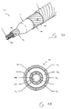
- Cable 70 includes an inner tube 72 and an outer tube 74, both of which are formed of helically wound copper or aluminum segments 76, 78 and include superconductor layers 80, 82, respectively.
- Inner tube 72 has a channel 84 (Fig. 9B) through which liquid cryogen flows and within which a steel or aluminum support helix 86 (Fig. 9A) is positioned.
- Inner tube 72 is spaced from outer tube 74 by a dielectric layer 88.
- Outer tube 74 is surrounded by a helically wound protective sheath 90.
- Electrostatic shields 92, 94 are also positioned along inner and outer surfaces, respectively, of dielectric layer 88.
- fault current limiter 10 is not solely limited for use in bus network 100 in Fig. 1, but can be connected within a variety of power transmission and distribution networks including those described in the article entitled "Fault Current Limiters using Superconductors", by W. T. Norris and A. Powers, Cryogenics (see attached article).
- fault current limiter 10 can be described above as a stand-alone device, it can be incorporated within other components of the system including within the housing of a transformer or a motor.
Landscapes
- Engineering & Computer Science (AREA)
- Power Engineering (AREA)
- Emergency Protection Circuit Devices (AREA)
- Containers, Films, And Cooling For Superconductive Devices (AREA)
Claims (21)
- Spulenaufbau (10, 50, 60) mit einer longitudinalen Achse, wobei der Spulenaufbau eine Vielzahl von in einer Stapelanordnung entlang der longitudinalen Achse angeordneten bifilaren Flachspulen (12) umfasst und wobei jede Spule ein Paar von leitenden Wicklungsabschnitten (32, 34) umfasst, die entlang einem innersten radialen Bereich der Spule aneinandergefügt, zusammen, eine über der anderen radial auswärts und um die longitudinale Achse herumgewickelt sind, dadurch gekennzeichnet, dass jede Flachspule (12) mit einer benachbarten Flachspule (12) elektrisch verbunden ist, sodass in benachbarten Windungen fließender Strom von benachbarten Flachspulen (12) in entgegengesetzten Richtungen bei allen radialen Bereichen des Spulenaufbaus (10) fließt.
- Spulenaufbau nach Anspruch 1, wobei die Wicklungsabsehnitte (32, 34) aus einem integralen Stück aus leitendem Material (14) gebildet sind.
- Spulenaufbau nach Anspruch 1 oder 2, wobei benachbarte bifilare Flachspulen (12a, 12b) elektrisch in Reihe verbunden sind.
- Spulenaufbau (50) nach einem der vorstehenden Ansprüche, ferner mit einem zweiten Paar von leitenden Wicklungen (12e, 12f), die entlang eines innersten radialen Bereichs der Spule aneinandergefügt, zusammen, eine über der anderen. radial auswärts und um die longitudinale Achse herumgewickelt sind, wobei jeder Wicklungsabsehnitt ein Ende an einem äußersten radialen Bereich der Spule aufweist, und wobei die zweite leitende Wicklung über die erst-erwähnte leitende Wicklung herumgewickelt und mit ihr parallel verbunden ist.
- Spulenaufbau nach einem der vorstehenden Ansprüche. wobei die leitende Wicklung (32. 34. 14) aus einem supraleitenden Material ist.
- Spulenaufbau nach Anspruch 5, wobei das supraleitende Material ein anisotropes hochtemperatursupraleitendes Material ist.
- Spulenaufbau nach Anspruch 6, wobei das anisotrope supraleitende Material ein Multi-Filament-Verbundleiter mit mehreren supraleitenden in einem matrixbildenden Material eingeschlossenen Filamenten ist.
- Spulenaufbau nach einem der Ansprüche 5 bis 7, wobei das supraleitende Material ein monolithisches supraleitendes Material ist.
- Spulenaufbau nach einem der Ansprüche 5 bis 8, wobei die supraleitend leitende Wicklung die Form eines supraleitenden Bandes (14) auweist.
- Spulenaufbau nach einem der Ansprüche 5 bis 9, wobei das supraleitend leitende Material (80. 82) die Form eines runden Koaxialkabels (70) aufweist.
- Fehlerstrombegrenzeraufbau (60) mit:einer Tragstruktur (64) mit einer zentralen Achse und einer Vielzahl von Tragelementen (66), jedes mit einer longitudinalen Achse, die radial mit einem vorbestimmten Abstand von der zentralen Achse beabstandet ist: undeiner Vielzahl von Spulenaufbauten (10a-10e), jeder entsprechend einem der vorstehenden Ansprüche, und jeder entlang einer entsprechenden der longitudinalen Achsen der Tragelemente (66) angeordnet.
- Fehlerstrombegrenzeraufbau nach Anspruch 11, ferner mit einer an Enden der Spulentraganordnung (64) positionierten Hochspannungsabschirmung (74).
- Fehlerstrombegrenzungsaufbau nach Anspruch 11 oder 12. wobei das Paar von leitenden Wicklungen von jeder magnetischen Spule aus einem supraleitenden Material ist.
- Verfahren zum Bereitstellen einer Fehlerstrom begrenzenden Spule (10, 50, 60) mit einer longitudinalen Achse, das Verfahren umfasst:Positionieren einer Vielzahl von bifilaren Flachspulen (12) in einer Stapelanordnung entlang der longitudinalen Achse der fehlerstrombegrenzenden Spule, wobei jede Flachspule ein Paar von leitenden Wicklungsabschnitten (32, 34) umfasst, die entlang eines innersten radialen Bereichs der Spule aneinandergefügt, zusammen, einer über den anderen, radial auswärts und um die longitudinale Achse herumgewickelt sind; und gekennzeichnet durchein elektrisches Verbinden benachbarter Flachspulen (12), sodass in benachbarten Windungen von benachbarten Flachspulen (12) fließender Strom in entgegengesetzten Richtungen fließt.
- Verfahren nach Anspruch 14, wobei das elektrische Verbinden benachbarter Flachspulen das in Reihe Verbinden der benachbarten Flachspulen (12a, 12b) umfasst.
- Verfahren nach Anspruch 14 oder 15, ferner mit einem Bereitstellen der Flachspulen (12) aus einem integralem Stück aus leitendem Material (14).
- Verfahren nach einem der Ansprüche 14 bis 16, wobei zumindest eine der bifilaren Flachspulen (12) ein Paar von bifilaren leitenden Wicklungen (12e, 12f). die übereinander und parallel herumgewickelt sind, umfasst.
- Verfahren nach einem der Ansprüche 14 bis 17, wobei die bifilaren Flachspulen (12) aus einem supraleitenden Material sind.
- Verfahren nach Anspruch 18, wobei das supraleitende Material ein anisotropes hochtemperatursupraleitendes Material in der Form eines supraleitendes Bandes ist.
- Verfahren nach Anspruch 19, wobei das anisotrope supraleitende Material ein Multi-Filament-Verbundleiter mit mehreren in einem matrixbildenden Material eingeschlossenen supraleitenden Filamenten ist.
- Verfahren nach einem der Ansprüche 18 bis 20, wobei das supraleitende Material ein monolithisches supraleitendes Material ist.
Applications Claiming Priority (2)
| Application Number | Priority Date | Filing Date | Title |
|---|---|---|---|
| US20431 | 1998-02-09 | ||
| US09/020,431 US6275365B1 (en) | 1998-02-09 | 1998-02-09 | Resistive fault current limiter |
Publications (3)
| Publication Number | Publication Date |
|---|---|
| EP0935261A2 EP0935261A2 (de) | 1999-08-11 |
| EP0935261A3 EP0935261A3 (de) | 2000-08-02 |
| EP0935261B1 true EP0935261B1 (de) | 2005-04-27 |
Family
ID=21798593
Family Applications (1)
| Application Number | Title | Priority Date | Filing Date |
|---|---|---|---|
| EP99300920A Revoked EP0935261B1 (de) | 1998-02-09 | 1999-02-09 | Resistiver Fehlerstrombegrenzer |
Country Status (3)
| Country | Link |
|---|---|
| US (1) | US6275365B1 (de) |
| EP (1) | EP0935261B1 (de) |
| DE (1) | DE69924898T2 (de) |
Cited By (1)
| Publication number | Priority date | Publication date | Assignee | Title |
|---|---|---|---|---|
| WO2024253280A1 (ko) * | 2023-06-09 | 2024-12-12 | 엘에스일렉트릭 주식회사 | 초전도 한류기 |
Families Citing this family (30)
| Publication number | Priority date | Publication date | Assignee | Title |
|---|---|---|---|---|
| US6657533B2 (en) * | 1998-11-25 | 2003-12-02 | American Semiconductor Corporation | Superconducting conductors and their method of manufacture |
| WO2002013353A2 (en) | 2000-08-04 | 2002-02-14 | American Superconductor Corporation | Stator coil assembly for superconducting rotating machines |
| EP1220337A1 (de) * | 2000-12-27 | 2002-07-03 | Abb Research Ltd. | Supraleitender Strombegrenzer |
| JP2004531052A (ja) * | 2001-01-17 | 2004-10-07 | アイジーシー−スーパーパワー、リミテッド ライアビリティー カンパニー | マトリクス型超伝導障害電流制限器 |
| US6528859B2 (en) * | 2001-05-11 | 2003-03-04 | Koninklijke Philips Electronics N.V. | Foil wound low profile L-C power processor |
| US6873236B2 (en) * | 2001-10-24 | 2005-03-29 | General Electric Company | Fault current limiter |
| DE20210213U1 (de) * | 2002-07-02 | 2002-10-17 | FRIWO Gerätebau GmbH, 48346 Ostbevern | Schutzvorrichtung für elektrische Geräte |
| US6947265B2 (en) * | 2003-06-16 | 2005-09-20 | Superpower, Inc. | Matrix current limiter with transformer configurations |
| US6809910B1 (en) | 2003-06-26 | 2004-10-26 | Superpower, Inc. | Method and apparatus to trigger superconductors in current limiting devices |
| US6958893B2 (en) * | 2003-06-30 | 2005-10-25 | Superpower Inc. | Superconducting matrix fault current limiter with current-driven trigger mechanism |
| KR100505054B1 (ko) * | 2003-09-30 | 2005-08-02 | 엘에스산전 주식회사 | 초전도 저항형 한류기 |
| DE102004046442A1 (de) * | 2004-09-24 | 2006-04-06 | Siemens Ag | Anordnung zum Schutz von elektronischen Komponenten |
| US7440244B2 (en) * | 2005-04-02 | 2008-10-21 | Superpower, Inc. | Self-triggering superconducting fault current limiter |
| KR101028817B1 (ko) * | 2005-05-25 | 2011-04-12 | 현대중공업 주식회사 | 무유도 권선형의 고온 초전도 전류 제한기 |
| EP1830419B1 (de) | 2006-03-02 | 2009-07-01 | Theva Dünnschichttechnik GmbH | Resistiver Strombegrenzer |
| US20080194411A1 (en) * | 2007-02-09 | 2008-08-14 | Folts Douglas C | HTS Wire |
| US20080190646A1 (en) * | 2007-02-09 | 2008-08-14 | Folts Douglas C | Parallel connected hts fcl device |
| US20080191561A1 (en) * | 2007-02-09 | 2008-08-14 | Folts Douglas C | Parallel connected hts utility device and method of using same |
| US20090156409A1 (en) * | 2007-12-17 | 2009-06-18 | Superpower, Inc. | Fault current limiter incorporating a superconducting article |
| KR100929394B1 (ko) * | 2008-01-30 | 2009-12-02 | 연세대학교 산학협력단 | 이종 초전도선재를 이용한 전류 제한 모듈 및 하이브리드전류 제한기 |
| WO2009095930A1 (en) | 2008-02-12 | 2009-08-06 | Deo Prafulla | An electromagnetic current limiter device |
| DE102008029722B3 (de) * | 2008-06-23 | 2009-12-17 | Siemens Aktiengesellschaft | Leiteranordnung für ein resistives Schaltelement mit wenigstens zwei Leiterverbünden aus supraleitenden Leiterbändern |
| FI126486B (fi) | 2010-09-23 | 2017-01-13 | Valmet Automation Oy | Sähkömagneetti matalakenttäisiin ydinmagneettiresonanssimittauksiin ja menetelmä sen valmistamiseksi |
| WO2012048169A2 (en) * | 2010-10-07 | 2012-04-12 | Advanced Magnet Lab, Inc. | Power transmission systems and components for direct current applications |
| US9012779B2 (en) | 2012-03-30 | 2015-04-21 | American Superconductor Corporation | Reduced-loss bucking bundle low voltage cable |
| CN103414176B (zh) * | 2013-07-30 | 2016-01-20 | 江苏多维科技有限公司 | 一种磁阻限流器 |
| ES2559610T3 (es) | 2013-09-03 | 2016-02-15 | Nexans | Disposición de bobina superconductora |
| CN107210356A (zh) * | 2014-12-22 | 2017-09-26 | 科技创新动量基金(以色列)参股有限公司 | 用于超导装置的电介质衬底和使用这种衬底的超导产品 |
| FR3076060B1 (fr) | 2017-12-22 | 2024-04-26 | Inst Supergrid | Dipole limiteur de courant a supraconducteur, comportant au moins quatre cables supraconducteurs |
| FR3081259B1 (fr) | 2018-05-17 | 2022-01-28 | Inst Supergrid | Limiteur de courant supraconducteur avec entretoise electriquement conductrice |
Family Cites Families (15)
| Publication number | Priority date | Publication date | Assignee | Title |
|---|---|---|---|---|
| US3737831A (en) * | 1965-03-12 | 1973-06-05 | Ite Imperial Corp | Resistor assembly with compression plate supports |
| US3569883A (en) * | 1969-09-15 | 1971-03-09 | Robert I Van Nice | Electrical winding |
| KR910003660B1 (ko) | 1987-11-09 | 1991-06-08 | 가부시끼가이샤 도시바 | 초전도 한류기(superconducting current limiting apparatus) |
| GB9104513D0 (en) | 1991-03-04 | 1991-04-17 | Boc Group Plc | Cryogenic apparatus |
| DE4107685A1 (de) | 1991-03-09 | 1992-09-10 | Abb Patent Gmbh | Supraleitender strombegrenzer |
| JP3131909B2 (ja) | 1991-06-03 | 2001-02-05 | 工業技術院長 | 超電導応用限流装置 |
| JPH04359626A (ja) | 1991-06-04 | 1992-12-11 | Tokyo Electric Power Co Inc:The | 限流装置 |
| US5140266A (en) * | 1991-06-05 | 1992-08-18 | General Electric Company | Apparatus and method for the non-destructive evaluation of a bifilar superconducting winding |
| AU4791793A (en) | 1992-07-31 | 1994-03-03 | Arch Development Corporation | High temperature superconducting fault current limiter |
| US5432666A (en) | 1993-01-22 | 1995-07-11 | Illinois Superconductor Corporation | Self-restoring fault current limiter utilizing high temperature superconductor components |
| DE69401722T2 (de) | 1993-03-26 | 1997-07-03 | Ngk Insulators Ltd | Supraleitende Anordnung zur Fehlerstrombegrenzung |
| US5531015A (en) * | 1994-01-28 | 1996-07-02 | American Superconductor Corporation | Method of making superconducting wind-and-react coils |
| US5551532A (en) | 1994-02-28 | 1996-09-03 | Otis Elevator Company | Method for transmitting messages in an elevator communications system |
| US5659277A (en) * | 1994-09-07 | 1997-08-19 | American Superconductor Corporation | Superconducting magnetic coil |
| GB2297432A (en) | 1995-01-28 | 1996-07-31 | Gec Alsthom Ltd | Superconductive fault current limiters |
-
1998
- 1998-02-09 US US09/020,431 patent/US6275365B1/en not_active Expired - Lifetime
-
1999
- 1999-02-09 DE DE69924898T patent/DE69924898T2/de not_active Expired - Lifetime
- 1999-02-09 EP EP99300920A patent/EP0935261B1/de not_active Revoked
Cited By (1)
| Publication number | Priority date | Publication date | Assignee | Title |
|---|---|---|---|---|
| WO2024253280A1 (ko) * | 2023-06-09 | 2024-12-12 | 엘에스일렉트릭 주식회사 | 초전도 한류기 |
Also Published As
| Publication number | Publication date |
|---|---|
| DE69924898T2 (de) | 2006-02-23 |
| EP0935261A2 (de) | 1999-08-11 |
| US6275365B1 (en) | 2001-08-14 |
| EP0935261A3 (de) | 2000-08-02 |
| DE69924898D1 (de) | 2005-06-02 |
Similar Documents
| Publication | Publication Date | Title |
|---|---|---|
| US6275365B1 (en) | Resistive fault current limiter | |
| EP1691381B1 (de) | Fehlerstrom begrenzende supraleitende Spule | |
| AU2008216583B2 (en) | HTS wire | |
| JP4620637B2 (ja) | 抵抗型超電導限流器 | |
| EP1441366B1 (de) | Supraleitendes kabel und supraleitende kabelleitung | |
| CA2356983C (en) | Electrical power transmission system using superconductors | |
| US20080194411A1 (en) | HTS Wire | |
| EP1830446B1 (de) | Strombegrenzer | |
| JPH01303765A (ja) | 電流制限器 | |
| CN102217160A (zh) | 故障电流超导限制器 | |
| US6762673B1 (en) | Current limiting composite material | |
| Rogers et al. | Superconducting fault current limiter and inductor design | |
| Escamez et al. | Towards the development of new DC railway system architectures with the use of superconducting devices | |
| AU2002318900B2 (en) | Fault Current Limiting Superconducting Coil | |
| GB2350485A (en) | A fault current limiter | |
| JPH07272960A (ja) | 超電導限流器 | |
| MXPA00002588A (en) | Fault current limiting superconducting coil |
Legal Events
| Date | Code | Title | Description |
|---|---|---|---|
| PUAI | Public reference made under article 153(3) epc to a published international application that has entered the european phase |
Free format text: ORIGINAL CODE: 0009012 |
|
| 17P | Request for examination filed |
Effective date: 19990219 |
|
| AK | Designated contracting states |
Kind code of ref document: A2 Designated state(s): CH DE FR GB IT LI SE |
|
| AX | Request for extension of the european patent |
Free format text: AL;LT;LV;MK;RO;SI |
|
| PUAL | Search report despatched |
Free format text: ORIGINAL CODE: 0009013 |
|
| AK | Designated contracting states |
Kind code of ref document: A3 Designated state(s): AT BE CH CY DE DK ES FI FR GB GR IE IT LI LU MC NL PT SE |
|
| AX | Request for extension of the european patent |
Free format text: AL;LT;LV;MK;RO;SI |
|
| AKX | Designation fees paid |
Free format text: CH DE FR GB IT LI SE |
|
| 17Q | First examination report despatched |
Effective date: 20010907 |
|
| GRAP | Despatch of communication of intention to grant a patent |
Free format text: ORIGINAL CODE: EPIDOSNIGR1 |
|
| RIN1 | Information on inventor provided before grant (corrected) |
Inventor name: SNITCHLER, GREGORY L. Inventor name: KALSI, SWARN S. |
|
| GRAS | Grant fee paid |
Free format text: ORIGINAL CODE: EPIDOSNIGR3 |
|
| GRAA | (expected) grant |
Free format text: ORIGINAL CODE: 0009210 |
|
| AK | Designated contracting states |
Kind code of ref document: B1 Designated state(s): CH DE FR GB IT LI SE |
|
| PG25 | Lapsed in a contracting state [announced via postgrant information from national office to epo] |
Ref country code: LI Free format text: LAPSE BECAUSE OF FAILURE TO SUBMIT A TRANSLATION OF THE DESCRIPTION OR TO PAY THE FEE WITHIN THE PRESCRIBED TIME-LIMIT Effective date: 20050427 Ref country code: CH Free format text: LAPSE BECAUSE OF FAILURE TO SUBMIT A TRANSLATION OF THE DESCRIPTION OR TO PAY THE FEE WITHIN THE PRESCRIBED TIME-LIMIT Effective date: 20050427 |
|
| REG | Reference to a national code |
Ref country code: GB Ref legal event code: FG4D |
|
| REG | Reference to a national code |
Ref country code: CH Ref legal event code: EP |
|
| REF | Corresponds to: |
Ref document number: 69924898 Country of ref document: DE Date of ref document: 20050602 Kind code of ref document: P |
|
| PG25 | Lapsed in a contracting state [announced via postgrant information from national office to epo] |
Ref country code: SE Free format text: LAPSE BECAUSE OF FAILURE TO SUBMIT A TRANSLATION OF THE DESCRIPTION OR TO PAY THE FEE WITHIN THE PRESCRIBED TIME-LIMIT Effective date: 20050727 |
|
| REG | Reference to a national code |
Ref country code: CH Ref legal event code: PL |
|
| PLBI | Opposition filed |
Free format text: ORIGINAL CODE: 0009260 |
|
| ET | Fr: translation filed | ||
| PLAX | Notice of opposition and request to file observation + time limit sent |
Free format text: ORIGINAL CODE: EPIDOSNOBS2 |
|
| 26 | Opposition filed |
Opponent name: SIEMENS AG Effective date: 20060117 |
|
| PLAF | Information modified related to communication of a notice of opposition and request to file observations + time limit |
Free format text: ORIGINAL CODE: EPIDOSCOBS2 |
|
| PLAF | Information modified related to communication of a notice of opposition and request to file observations + time limit |
Free format text: ORIGINAL CODE: EPIDOSCOBS2 |
|
| PLBB | Reply of patent proprietor to notice(s) of opposition received |
Free format text: ORIGINAL CODE: EPIDOSNOBS3 |
|
| APAH | Appeal reference modified |
Free format text: ORIGINAL CODE: EPIDOSCREFNO |
|
| APBM | Appeal reference recorded |
Free format text: ORIGINAL CODE: EPIDOSNREFNO |
|
| APBP | Date of receipt of notice of appeal recorded |
Free format text: ORIGINAL CODE: EPIDOSNNOA2O |
|
| APBM | Appeal reference recorded |
Free format text: ORIGINAL CODE: EPIDOSNREFNO |
|
| APBP | Date of receipt of notice of appeal recorded |
Free format text: ORIGINAL CODE: EPIDOSNNOA2O |
|
| APBQ | Date of receipt of statement of grounds of appeal recorded |
Free format text: ORIGINAL CODE: EPIDOSNNOA3O |
|
| APBQ | Date of receipt of statement of grounds of appeal recorded |
Free format text: ORIGINAL CODE: EPIDOSNNOA3O |
|
| PGFP | Annual fee paid to national office [announced via postgrant information from national office to epo] |
Ref country code: IT Payment date: 20120224 Year of fee payment: 14 |
|
| PGFP | Annual fee paid to national office [announced via postgrant information from national office to epo] |
Ref country code: DE Payment date: 20130227 Year of fee payment: 15 Ref country code: FR Payment date: 20130311 Year of fee payment: 15 Ref country code: GB Payment date: 20130227 Year of fee payment: 15 |
|
| REG | Reference to a national code |
Ref country code: DE Ref legal event code: R103 Ref document number: 69924898 Country of ref document: DE Ref country code: DE Ref legal event code: R064 Ref document number: 69924898 Country of ref document: DE |
|
| APBU | Appeal procedure closed |
Free format text: ORIGINAL CODE: EPIDOSNNOA9O |
|
| RDAF | Communication despatched that patent is revoked |
Free format text: ORIGINAL CODE: EPIDOSNREV1 |
|
| RDAG | Patent revoked |
Free format text: ORIGINAL CODE: 0009271 |
|
| STAA | Information on the status of an ep patent application or granted ep patent |
Free format text: STATUS: PATENT REVOKED |
|
| 27W | Patent revoked |
Effective date: 20140108 |
|
| GBPR | Gb: patent revoked under art. 102 of the ep convention designating the uk as contracting state |
Effective date: 20140108 |
|
| REG | Reference to a national code |
Ref country code: DE Ref legal event code: R107 Ref document number: 69924898 Country of ref document: DE Effective date: 20140828 |
|
| REG | Reference to a national code |
Ref country code: CH Ref legal event code: PK Free format text: DAS DATUM DES WIDERRUFS DURCH EPA IST NICHT KORREKT |