EP0724532B1 - Emballage pourvu d'un systeme de verrouillage du fond - Google Patents
Emballage pourvu d'un systeme de verrouillage du fond Download PDFInfo
- Publication number
- EP0724532B1 EP0724532B1 EP95925510A EP95925510A EP0724532B1 EP 0724532 B1 EP0724532 B1 EP 0724532B1 EP 95925510 A EP95925510 A EP 95925510A EP 95925510 A EP95925510 A EP 95925510A EP 0724532 B1 EP0724532 B1 EP 0724532B1
- Authority
- EP
- European Patent Office
- Prior art keywords
- flap
- bottom panel
- retainer
- carrier
- wrap
- Prior art date
- Legal status (The legal status is an assumption and is not a legal conclusion. Google has not performed a legal analysis and makes no representation as to the accuracy of the status listed.)
- Expired - Lifetime
Links
Images

Classifications
-
- B—PERFORMING OPERATIONS; TRANSPORTING
- B65—CONVEYING; PACKING; STORING; HANDLING THIN OR FILAMENTARY MATERIAL
- B65D—CONTAINERS FOR STORAGE OR TRANSPORT OF ARTICLES OR MATERIALS, e.g. BAGS, BARRELS, BOTTLES, BOXES, CANS, CARTONS, CRATES, DRUMS, JARS, TANKS, HOPPERS, FORWARDING CONTAINERS; ACCESSORIES, CLOSURES, OR FITTINGS THEREFOR; PACKAGING ELEMENTS; PACKAGES
- B65D71/00—Bundles of articles held together by packaging elements for convenience of storage or transport, e.g. portable segregating carrier for plural receptacles such as beer cans or pop bottles; Bales of material
- B65D71/06—Packaging elements holding or encircling completely or almost completely the bundle of articles, e.g. wrappers
- B65D71/12—Packaging elements holding or encircling completely or almost completely the bundle of articles, e.g. wrappers the packaging elements, e.g. wrappers being formed by folding a single blank
- B65D71/14—Packaging elements holding or encircling completely or almost completely the bundle of articles, e.g. wrappers the packaging elements, e.g. wrappers being formed by folding a single blank having the shape of a tube, without, or not being characterised by, end walls
- B65D71/16—Packaging elements holding or encircling completely or almost completely the bundle of articles, e.g. wrappers the packaging elements, e.g. wrappers being formed by folding a single blank having the shape of a tube, without, or not being characterised by, end walls with article-locating elements
- B65D71/18—Tabs inwardly folded tabs from the upper or lower wall
-
- B—PERFORMING OPERATIONS; TRANSPORTING
- B65—CONVEYING; PACKING; STORING; HANDLING THIN OR FILAMENTARY MATERIAL
- B65D—CONTAINERS FOR STORAGE OR TRANSPORT OF ARTICLES OR MATERIALS, e.g. BAGS, BARRELS, BOTTLES, BOXES, CANS, CARTONS, CRATES, DRUMS, JARS, TANKS, HOPPERS, FORWARDING CONTAINERS; ACCESSORIES, CLOSURES, OR FITTINGS THEREFOR; PACKAGING ELEMENTS; PACKAGES
- B65D2571/00—Bundles of articles held together by packaging elements for convenience of storage or transport, e.g. portable segregating carrier for plural receptacles such as beer cans, pop bottles; Bales of material
- B65D2571/00123—Bundling wrappers or trays
- B65D2571/00129—Wrapper locking means
- B65D2571/00135—Wrapper locking means integral with the wrapper
- B65D2571/00154—Wrapper locking means integral with the wrapper interlocked
- B65D2571/0016—Wrapper locking means integral with the wrapper interlocked by tabs protruding from one end and co-operating with openings at the other end
- B65D2571/00166—Wrapper locking means integral with the wrapper interlocked by tabs protruding from one end and co-operating with openings at the other end and serving as contents separators or locators
-
- B—PERFORMING OPERATIONS; TRANSPORTING
- B65—CONVEYING; PACKING; STORING; HANDLING THIN OR FILAMENTARY MATERIAL
- B65D—CONTAINERS FOR STORAGE OR TRANSPORT OF ARTICLES OR MATERIALS, e.g. BAGS, BARRELS, BOTTLES, BOXES, CANS, CARTONS, CRATES, DRUMS, JARS, TANKS, HOPPERS, FORWARDING CONTAINERS; ACCESSORIES, CLOSURES, OR FITTINGS THEREFOR; PACKAGING ELEMENTS; PACKAGES
- B65D2571/00—Bundles of articles held together by packaging elements for convenience of storage or transport, e.g. portable segregating carrier for plural receptacles such as beer cans, pop bottles; Bales of material
- B65D2571/00123—Bundling wrappers or trays
- B65D2571/00129—Wrapper locking means
- B65D2571/00135—Wrapper locking means integral with the wrapper
- B65D2571/00154—Wrapper locking means integral with the wrapper interlocked
- B65D2571/00172—Wrapper locking means integral with the wrapper interlocked by tabs cut within one end and facing towards the other end when blank is unfolded, and co-operting with openings at the other end
-
- B—PERFORMING OPERATIONS; TRANSPORTING
- B65—CONVEYING; PACKING; STORING; HANDLING THIN OR FILAMENTARY MATERIAL
- B65D—CONTAINERS FOR STORAGE OR TRANSPORT OF ARTICLES OR MATERIALS, e.g. BAGS, BARRELS, BOTTLES, BOXES, CANS, CARTONS, CRATES, DRUMS, JARS, TANKS, HOPPERS, FORWARDING CONTAINERS; ACCESSORIES, CLOSURES, OR FITTINGS THEREFOR; PACKAGING ELEMENTS; PACKAGES
- B65D2571/00—Bundles of articles held together by packaging elements for convenience of storage or transport, e.g. portable segregating carrier for plural receptacles such as beer cans, pop bottles; Bales of material
- B65D2571/00123—Bundling wrappers or trays
- B65D2571/00246—Locating elements for the contents
- B65D2571/00253—Locating elements for the contents integral with the wrapper
- B65D2571/00277—Slits or openings formed along a fold line
-
- B—PERFORMING OPERATIONS; TRANSPORTING
- B65—CONVEYING; PACKING; STORING; HANDLING THIN OR FILAMENTARY MATERIAL
- B65D—CONTAINERS FOR STORAGE OR TRANSPORT OF ARTICLES OR MATERIALS, e.g. BAGS, BARRELS, BOTTLES, BOXES, CANS, CARTONS, CRATES, DRUMS, JARS, TANKS, HOPPERS, FORWARDING CONTAINERS; ACCESSORIES, CLOSURES, OR FITTINGS THEREFOR; PACKAGING ELEMENTS; PACKAGES
- B65D2571/00—Bundles of articles held together by packaging elements for convenience of storage or transport, e.g. portable segregating carrier for plural receptacles such as beer cans, pop bottles; Bales of material
- B65D2571/00123—Bundling wrappers or trays
- B65D2571/00648—Elements used to form the wrapper
- B65D2571/00654—Blanks
- B65D2571/0066—Blanks formed from one single sheet
-
- B—PERFORMING OPERATIONS; TRANSPORTING
- B65—CONVEYING; PACKING; STORING; HANDLING THIN OR FILAMENTARY MATERIAL
- B65D—CONTAINERS FOR STORAGE OR TRANSPORT OF ARTICLES OR MATERIALS, e.g. BAGS, BARRELS, BOTTLES, BOXES, CANS, CARTONS, CRATES, DRUMS, JARS, TANKS, HOPPERS, FORWARDING CONTAINERS; ACCESSORIES, CLOSURES, OR FITTINGS THEREFOR; PACKAGING ELEMENTS; PACKAGES
- B65D2571/00—Bundles of articles held together by packaging elements for convenience of storage or transport, e.g. portable segregating carrier for plural receptacles such as beer cans, pop bottles; Bales of material
- B65D2571/00123—Bundling wrappers or trays
- B65D2571/00709—Shape of the formed wrapper, i.e. shape of each formed element if the wrapper is made from more than one element
- B65D2571/00716—Shape of the formed wrapper, i.e. shape of each formed element if the wrapper is made from more than one element tubular without end walls
Definitions
- This invention relates to a wrap-around article carrier according to the preamble of claim 1 and to a blank for forming same as defined in the preamble of claim 9.
- This invention thus deals with article carriers having at least partially open ends and bottom panels formed from bottom panel flaps.
- Wrap-around article carriers are commonly designed to have ends which are either partially or entirely open. In either case the carriers must be provided with means for preventing the articles from falling out the ends.
- Beverage cans for example, are held in place partly by the tension of the tightly wrapped carrier and by engagement of the top and bottom flanges of the cans with the edges of cutouts in the side panels of the carrier through which the flanges of the cans extend. This design is facilitated by the fact that cans have substantially flat tops and bottoms of the same diameter as the body of the can, which allows the carrier blank to be tightly wrapped around the cans.
- Partial end panels extending up from the bottom panel could be provided to function as article retainers, as could corner end gusset panels or flaps. These measures are not entirely satisfactory, however, because they require extra material to be used, making the carrier more costly to produce, and do not prevent movement of the bottom portions of the containers toward and away from each other.
- retaining flaps which are wedged between the bottom portions of adjacent tubs to hold them in place.
- Such a structure is known for example from US 5094347 disclosing a wrap-around carrier of the generic type and a corresponding blank.
- This document suggests integral retaining means in an open-ended wrap-around carrier for preventing articles such as bottles from escaping the carrier through the open end.
- the bottom panel is comprised of inner and outer mechanically connected flaps.
- the outer bottom panel flap contains a retainer flap at each end connected along a fold line which is generally parallel to the open end edge of the bottom panel.
- the retainer flaps extend up into the interior of the carrier through openings in the inner bottom panel flap.
- the retainer flap is folded along converging fold lines so that it forms a retainer end edge to the first panel and extends along a notional line to its leading end edge.
- the locking tab has opposite side edges extending between the leading and trailing end edges and a lateral projection protruding from one of the side edges.
- the retaining tab is foldably joined to the second panel and defines at least a part of a locking aperture in the second panel.
- the biasing tab is foldably joined to the second panel along a transverse edge of the locking aperture and projects from the transverse edge in the direction parallel to the notional line.
- the locking tab is folded out of the plane of the first panel into the locking aperture and is disposed in the position where the locking tab is inclined to the second panel.
- the retaining tab is folded out of the plane of the second panel into the position where the retaining tab is engaged at its free end edge with the lateral projection of the locking tab.
- the biasing tab is folded out of the plane of the second panel into the position where the biasing tab leans against the locking tab.
- a wrap-around carrier having a top panel and side panels is provided with a bottom panel comprised of overlapping bottom panel flaps foldably connected to the side panels.
- a first or inner bottom panel flap incorporates hinged article retaining flaps which are folded up into the interior of the carrier so as to engage the bottom portions of adjacent spaced articles.
- the second or outer bottom panel flap includes bottom panel locking tabs which engage and maintain the retainer flaps in folded operative condition.
- the locking tabs include a shoulder extending over an edge of an associated retaining flap to prevent withdrawal of the locking tabs from their engagement with the retaining flaps.
- each retainer flap includes foldably connected side extensions which contact the bottom portions of adjacent spaced articles. The edges of the retainer flaps associated with the locking tab shoulders extend between the side extensions.
- the activated retainer flap is three dimensional, having a central section directed toward the interior of the carrier and the side extensions extending between adjacent end articles. Because the retainer flap fits snugly between the spaced bottom portions of the end articles, the articles are held in place against outward movement.
- the first bottom panel flap further includes slits which are essentially continuations of slits in the retaining flaps, the combined slits receiving an associated locking tab as it is initially moved into the interior of the carrier during formation of a package.
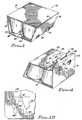
- a wrap-around carrier 10 comprises a top panel 12 connected along fold lines 14 to side panels 16 which generally follow the contour of tapered articles T in the carrier.
- the articles T are shown as comprising tubs of the type used to contain soft food, such as pudding or margarine or the like. It can be seen that the side panels are inwardly tapered at the bottom portion of the carrier as a result of being tightly wrapped around the sloped side portions of the tubs.
- the side panels adjacent the bottom panel are provided with cutouts or apertures 18 through which the bottom portions of the tubs T extend.
- the bottom panel is formed by overlapped inner and outer bottom panel flaps 20 and 22.
- the inner bottom panel flap 20 is connected to one of the side panels 16 along fold line 24 while the outer bottom panel flap 22 is connected to the other side panel 16 along fold line 26.
- Extending up from the bottom panel adjacent the end articles T in the adjacent rows of articles is a retainer flap 28.
- the retainer flap is contoured, as described more fully below, and fits snugly between the angled bottom portions of the articles T, preventing the bottom portions from moving either toward the open end of the carrier or in a transverse direction away from the side panels 16.
- a blank for forming the carrier 10 comprises a substantially rectangular sheet 30 of paperboard or other suitable material having adequate flexibility and strength, with the top panel section 12 being centrally located and the other panel sections described above being successively connected along the fold lines referred to above.
- the inner bottom panel flap 20 incorporates the retainer flaps 28 at opposite ends as well as primary female locking openings 32 between the flaps.
- the outer bottom panel flap 22 includes a fold line 34 spaced from and parallel to the fold line 26.
- Primary locking tabs 36 are formed by slits 38 which interrupt the fold line 32.
- Two spaced secondary locking tabs 40 are connected to the flap 22 along fold lines 42. The edges of the locking tabs 40 that face each other curve toward the blank and terminate adjacent the end edge of the bottom panel flap 22 in spaced shoulders 44, while the edges of the tabs facing away from each other terminate in projections such as catch hooks or shoulders 46.
- each retainer flap structure 28 is connected to the inner bottom panel flap 20 by a fold line 48 which is spaced from and substantially parallel to an end edge of the flap 20.
- Identical slits 50 extend transversely from the ends of the fold line 48 and connect with the ends of slit 52, which is parallel to the fold line 48.
- Curved fold lines 54 extend from spaced points on the slit 52 to points on the slits 50 to form identical spaced extensions 56 of the retainer flap.
- the main body 57 of the retainer flap is thus connected to the bottom panel flap 20 by the fold line 48 and extends between the extensions 56.
- a slit 58 extends from outside the retainer flap structure into the narrow neck of the retainer flap body between the extensions 56 and terminates in a cross slit 60 to form a T-shaped cut.
- the portions of the retainer flap connected to the fold line 54 and slits 58, 60 and 52 comprise flaps or wings 61.
- an S-shaped slit 62 in the bottom panel flap 20 connects with the end of the slit 58 located outside the retainer flap 28.
- the blank 30 is wrapped around the tubs or other articles to be packaged with the inner bottom panel flap 20 folded down against the bottoms of the tubs and the outer bottom panel flap 22 folded back along fold line 34 as illustrated in FIG. 4. This moves the primary locking tabs 36 out of the plane of the bottom panel flap 22. With the primary locking tabs 36 thus exposed, the outer bottom panel flap 22 is folded down about the fold line 26 and the tabs 36 are caused to enter the primary locking openings 32 of the inner bottom panel flap. The outer portion of the outer bottom panel flap is then folded down about fold line 34 and the secondary locking tabs 40 are folded down about their fold lines 42 so as to enter the slits 58.
- the S-shaped slits 62 be provided at the ends of the slits 58, this structure is preferred because it enables the locking tabs 40 to readily enter the slits while providing a degree of protection against subsequent withdrawal.
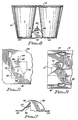
- FIG. 5 which illustrates the location of a locking tab 40, shown in broken lines, as it is about to enter an associated slit 58, the tabs 40 push aside the small tabs 64 formed by the S-shaped slits as the tabs 40 enter the slits 58. Then when the small tabs snap back to their original position after the shoulder 44 of the locking tabs 40 have passed, they prevent easy withdrawal of the locking tabs.
- FIG. 9 shows the bottom of the carrier of FIG. 1. Note that the structure visible in this view is seen through the opening in the bottom panel flap 20 which has been vacated by the inward pivoting of the retainer flap structure.
- main retainer flap bodies may be modified as shown in FIG. 10, wherein the flap body 57' is connected to the bottom panel flap 20 by short fold lines 48' separated by a cutout in the flap body, thus forming legs 68.
- This arrangement requires less force to fold the flap body into operative position and may be employed where this is a concern.
- the dimensions of the retaining flap and the location of the side extension fold lines are selected to cause the retainer flap extensions to engage and be folded against adjacent articles in the carrier. It is preferred that the wing flaps 61 be present for the extra stability and the additional support surface which they provide. It will be appreciated, however, that even if they were eliminated, so that a cutout area is provided in their place, the locking tabs 40 would still be positioned with respect to the retainer flap edge 64 so as to prevent withdrawal of the locking tabs from the retainer flaps.
- the article retaining means of the invention provides an effective retainer which engages substantial portions of the end tubs or other articles in a carrier which have spaced bottom portions, and does so without adding to the material cost of the carrier blank.
- the retaining means provides an additional mechanical lock between the flaps forming the bottom panel, thus further ensuring against the accidental escape of articles from the carrier through failure of the bottom panel.
- the top panel may be provided with handle openings if desired, to facilitate lifting and carrying.
- While the invention has been illustrated in connection with tub-shaped articles, it may also be employed to hold articles of different shapes, including beverage bottles and cans, against outward movement in a carrier.
Landscapes
- Engineering & Computer Science (AREA)
- Mechanical Engineering (AREA)
- Packages (AREA)
- Led Device Packages (AREA)
- Electrochromic Elements, Electrophoresis, Or Variable Reflection Or Absorption Elements (AREA)
- Electron Tubes For Measurement (AREA)
- Bathtub Accessories (AREA)
- Saccharide Compounds (AREA)
- Massaging Devices (AREA)
- Cartons (AREA)
- Details Of Rigid Or Semi-Rigid Containers (AREA)
- Casings For Electric Apparatus (AREA)
- Pens And Brushes (AREA)
- Closures For Containers (AREA)
Claims (13)
- Support enveloppant pour articles (10) contenant une pluralité de rangées adjacentes d'articles (T) dont les parties inférieures sont espacées, comprenant :caractérisé en ce que :un panneau supérieur (12) ;des panneaux latéraux opposés (16) reliés au panneau supérieur (12) ;un panneau inférieur constitué d'un premier volet de panneau inférieur (20) relié à un de ses bords latéraux à l'un des panneaux latéraux (16) et un deuxième volet de panneau inférieur (22) relié à un de ses bords latéraux à l'autre panneau latéral (16), chaque volet de panneau inférieur comportant des bords d'extrémité opposés ;le premier volet de panneau inférieur (20) comprenant un volet de retenue d'articles d'un seul tenant (28) articulé sur lui en un emplacement adjacent à chaque bord d'extrémité du premier volet de panneau inférieur, les volets de retenue d'articles (28) étant pliés vers le haut depuis le premier volet de panneau inférieur dans l'intérieur du support de manière à engager les parties inférieures d'articles espacés adjacents (T) ;le deuxième volet de panneau inférieur (22) comprenant une patte de verrouillage (40) associée à chaque volet de retenue (28), chaque volet de retenue engageant une patte de verrouillage associée pour maintenir le volet de retenue dans la condition pliée ; etun moyen pour empêcher l'extraction des pattes de verrouillage de leur engagement avec les volets de retenue ;chaque volet de retenue (28) comprenant des extensions latérales (56) reliées sur leurs côtés opposés le long de lignes de pliage (54), les extensions latérales (56) venant en contact avec les parties inférieures d'articles espacés, adjacents ;un bord de chaque volet de retenue (28) s'étendant entre les extensions latérales (56) ;le moyen pour empêcher l'extraction des pattes de verrouillage (40) comprend un épaulement (44) sur chaque patte s'étendant sur le bord du volet de retenue associé (28) etchaque volet de retenue (28) comprend deux volets d'ailettes espacés (61) reliés par des lignes de pliage aux extensions latérales opposées (56), les volets d'ailes (61) engageant des côtés opposés d'une patte de verrouillage associée (40).
- Support enveloppant pour articles selon la revendication 1, dans lequel ledit bord de chaque volet de retenue (28) engage une patte de verrouillage associée (40) sous l'épaulement (44) sur elle de manière à maintenir le volet de retenue (28) dans la condition pliée.
- Support enveloppant pour articles selon la revendication 1, dans lequel chaque volet d'ailette (61) comprend un bord qui est espacé dudit bord d'un volet de retenue associé (28).
- Support enveloppant pour articles selon la revendication 1, dans lequel le premier volet de panneau inférieur (20) comprend des découpes résultant du pliage vers l'intérieur des volets de retenue (28), le premier volet de panneau inférieur comprenant également des fentes (58, 62) s'étendant l'une vers l'autre depuis des bords des découpes, chaque fente permettant au moins à une partie d'une patte de verrouillage associée (40) de la traverser tandis que les pattes de verrouillage sont déplacées dans l'intérieur du support.
- Support enveloppant pour articles selon la revendication 1, dans lequel les pattes de verrouillage (40) sont des pattes de verrouillage secondaire, le deuxième volet de panneau inférieur (22) contenant au moins une patte de verrouillage primaire (36) engageant une ouverture de verrouillage primaire (32) dans le premier volet de panneau inférieur (20).
- Support enveloppant pour articles selon la revendication 1, dans lequel la patte de verrouillage (40) est reliée par pliage au deuxième volet de panneau inférieur (22).
- Support enveloppant pour articles selon la revendication 1, dans lequel les volets de retenue d'articles (28) sont reliés par articulation au premier volet de panneau inférieur (20) le long de lignes de pliage (48) qui sont sensiblement parallèles aux bords d'extrémité du premier volet de panneau inférieur.
- Support enveloppant pour articles selon la revendication 7, dans lequel chaque volet de retenue d'articles comprend une découpe formant des jambages espacés (68), les jambages espacés (68) étant reliés par articulation au premier volet de panneau inférieur le long desdites lignes de pliage (48).
- Flan pour former un support enveloppant pour articles afin d'emballer une pluralité de rangées adjacentes d'articles dont les parties inférieures sont espacées, comprenant :caractérisé en ce que :une feuille généralement rectangulaire (30) comportant une section de panneau supérieur central (12) ;des sections de panneaux latéraux (16) reliées aux côtés opposés de la section de panneau supérieur (12) par des lignes de pliage (14) ;un premier volet de panneau inférieur (20) relié à l'une des sections de panneaux latéraux (16) le long d'une première ligne de pliage (24) et un deuxième volet de panneau inférieur (22) relié à l'autre section de panneau latéral (16) le long d'une deuxième ligne de pliage (26), chaque volet de panneau inférieur comportant des bords d'extrémité opposés ;le premier volet de panneau inférieur (20) comprenant un volet de retenue d'articles (28) articulé sur lui en un emplacement adjacent à chaque bord d'extrémité du premier volet de panneau inférieur ;le deuxième volet de panneau inférieur (22) comprenant une patte de verrouillage (40) pour engager un volet de retenue associé dans le premier volet de panneau inférieur dans un support formé à partir du flan pour plier le volet de retenue (28) dans l'intérieur du support et maintenir le volet de retenue (28) dans la condition pliée ; etun moyen pour empêcher l'extraction des pattes de verrouillage de leur engagement avec les volets de retenue ;chaque volet de retenue (28) comprenant des extensions latérales (56) reliées sur leurs côtés opposés le long de lignes de pliage (54), les extensions latérales (56) contactant les parties inférieures d'articles espacés, adjacents, dans un support formé à partir du flan ;un bord de chaque volet de retenue (28) s'étendant entre les extensions latérales (56) ;le moyen pour empêcher l'extraction des pattes de verrouillage (40) comprend un épaulement (44) sur chaque patte sous-jacent au bord du volet de retenue associé dans un support formé à partir du flan ; etchaque volet de retenue (28) comprend deux volets d'ailettes (61) reliés par des lignes de pliage (54) aux extensions latérales opposées et séparés par une fente (58), les volets d'ailettes (61) engageant des côtés opposés d'une patte de verrouillage associée (40) dans un support formé à partir du flan.
- Flan de support enveloppant selon la revendication 9, dans lequel le premier volet de panneau inférieur (20) comprend des fentes (58, 62) qui sont sensiblement des prolongements de la fente (58) séparant les volets d'ailettes adjacents, chaque fente permettant au moins à une partie d'une patte de verrouillage associée (40) de la traverser tandis que les pattes de verrouillage sont déplacées dans l'intérieur d'un support formé à partir du flan.
- Flan de support enveloppant selon la revendication 9, dans lequel les pattes de verrouillage (40) sont des pattes de verrouillage secondaire, le deuxième volet de panneau inférieur (22) contenant au moins une patte de verrouillage primaire (36) engageant une ouverture de verrouillage primaire (32) dans le premier volet de panneau inférieur (20).
- Flan de support enveloppant selon la revendication 9, dans lequel la patte de verrouillage (40) est reliée par pliage au deuxième volet de panneau inférieur (22).
- Flan de support enveloppant selon la revendication 9, dans lequel les volets de retenue d'articles (28) sont reliés au premier volet de panneau inférieur (20) le long de lignes de pliage (48) qui sont sensiblement parallèles aux bords d'extrémité du premier volet de panneau inférieur.
Applications Claiming Priority (3)
| Application Number | Priority Date | Filing Date | Title |
|---|---|---|---|
| US08/292,505 US5484059A (en) | 1994-08-18 | 1994-08-18 | Carrier with bottom panel lock |
| US292505 | 1994-08-18 | ||
| PCT/US1995/008447 WO1996006019A1 (fr) | 1994-08-18 | 1995-06-12 | Emballage pourvu d'un systeme de verrouillage du fond |
Publications (3)
| Publication Number | Publication Date |
|---|---|
| EP0724532A1 EP0724532A1 (fr) | 1996-08-07 |
| EP0724532A4 EP0724532A4 (fr) | 1999-07-28 |
| EP0724532B1 true EP0724532B1 (fr) | 2001-12-19 |
Family
ID=23124960
Family Applications (1)
| Application Number | Title | Priority Date | Filing Date |
|---|---|---|---|
| EP95925510A Expired - Lifetime EP0724532B1 (fr) | 1994-08-18 | 1995-06-12 | Emballage pourvu d'un systeme de verrouillage du fond |
Country Status (17)
| Country | Link |
|---|---|
| US (1) | US5484059A (fr) |
| EP (1) | EP0724532B1 (fr) |
| JP (1) | JP3482211B2 (fr) |
| KR (1) | KR960704776A (fr) |
| AT (1) | ATE211103T1 (fr) |
| AU (1) | AU686411B2 (fr) |
| BR (1) | BR9506053A (fr) |
| CA (1) | CA2172381C (fr) |
| CO (1) | CO4440519A1 (fr) |
| DE (1) | DE69524722T2 (fr) |
| ES (1) | ES2165920T3 (fr) |
| FI (1) | FI960484L (fr) |
| IL (1) | IL114977A0 (fr) |
| NO (1) | NO961516D0 (fr) |
| NZ (1) | NZ289695A (fr) |
| WO (1) | WO1996006019A1 (fr) |
| ZA (1) | ZA956874B (fr) |
Families Citing this family (51)
| Publication number | Priority date | Publication date | Assignee | Title |
|---|---|---|---|---|
| US5638956A (en) * | 1995-12-11 | 1997-06-17 | Riverwood International Corporation | Wrap-around carrier with lock-box keel |
| DE69717009D1 (de) * | 1996-01-31 | 2002-12-19 | Riverwood Int Corp | Verriegelnde kartonhülse |
| US5620094A (en) * | 1996-05-21 | 1997-04-15 | Riverwood International Corporation | Wrap-around carrier with top divider tab |
| US5671845A (en) * | 1996-09-06 | 1997-09-30 | Riverwood International Corporation | Wrap-around carrier panel lock and article retainer |
| US5765685A (en) * | 1997-06-10 | 1998-06-16 | Riverwood International Corporation | Carrier with article retaining means |
| CA2294610A1 (fr) | 1997-06-16 | 1998-12-23 | George Moshe Katz | Procedes d'etalonnage et de test d'un capteur servant a mesurer un analyte in vivo et dispositifs utilises dans ces procedes |
| US6105774A (en) * | 1999-03-31 | 2000-08-22 | Jackson; Lisa | Carton for packaging containers |
| US7204369B2 (en) * | 2001-03-02 | 2007-04-17 | Meadwestvaco Packaging Systems, Llc | Wraparound carton with inclined beam structure and blank therefor |
| US7014044B1 (en) * | 2004-03-05 | 2006-03-21 | Insulair, Inc. | Cup and lid holder and dispenser |
| JP2007534565A (ja) * | 2004-04-22 | 2007-11-29 | インシュライアー、インコーポレイテッド | 断熱用カップラッパー及びラッパーで形成された断熱された容器 |
| CN101395069B (zh) | 2006-01-17 | 2013-04-10 | 印刷包装国际公司 | 用于容器的包装 |
| NZ569990A (en) * | 2006-01-31 | 2011-05-27 | Graphic Packaging Int Inc | A top carrier package for containers |
| KR20080034526A (ko) | 2006-09-25 | 2008-04-22 | 씨제이 주식회사 | 증정제품 보호용 패드 |
| US7767049B2 (en) | 2006-10-12 | 2010-08-03 | Dixie Consumer Products Llc | Multi-layered container having interrupted corrugated insulating liner |
| ES2323109B1 (es) * | 2007-01-25 | 2010-02-12 | Graphic Packaging International, Inc. | "embalaje para recipientes". |
| US8256617B2 (en) * | 2008-03-28 | 2012-09-04 | Graphic Packaging International, Inc. | Carrier for containers |
| GB0914435D0 (en) | 2009-08-18 | 2009-09-30 | Meadwestvaco Packaging Systems | Carton and blank therefor |
| ES2613505T3 (es) | 2010-07-30 | 2017-05-24 | Graphic Packaging International, Inc. | Dispositivo de transporte para botellas |
| CA2816487C (fr) | 2010-12-03 | 2015-11-24 | Graphic Packaging International, Inc. | Emballage pour recipients |
| US9022217B2 (en) | 2011-05-06 | 2015-05-05 | Graphic Packaging International, Inc. | Carton with article protection feature |
| BR112013028448B1 (pt) | 2011-05-06 | 2020-07-21 | Graphic Packaging International, Llc | método de formar uma caixa de papelão |
| EP2707307B1 (fr) | 2011-05-13 | 2017-08-02 | Graphic Packaging International, Inc. | Emballage pour contenants |
| CN103687791A (zh) * | 2011-06-28 | 2014-03-26 | 盒子托盘和长颈鹿公司 | 饮料包装系统 |
| ES2641934T3 (es) | 2011-08-05 | 2017-11-14 | Graphic Packaging International, Inc. | Embalaje para recipientes |
| ES2567472T3 (es) | 2011-10-19 | 2016-04-22 | Graphic Packaging International, Inc. | Sistema y procedimiento para activar las características de protección de los artículos de una caja de cartón |
| WO2013130528A1 (fr) | 2012-02-27 | 2013-09-06 | Graphic Packaging International, Inc. | Carton à poignée renforcée |
| JP2014058321A (ja) * | 2012-09-14 | 2014-04-03 | Toppan Printing Co Ltd | スリーブ |
| WO2014124355A2 (fr) * | 2013-02-11 | 2014-08-14 | Graphic Packaging International, Inc. | Carton doté d'une poignée |
| US9840358B2 (en) | 2013-03-14 | 2017-12-12 | Graphic Packaging International, Inc. | Carton with article protection feature |
| BR112015025302B1 (pt) | 2013-04-10 | 2022-06-07 | Graphic Packaging International, Llc | Embalagem para alojar pelo menos um artigo, matriz para formar uma embalagem para alojar pelo menos um artigo, embalagem para alojar pelo menos um artigo, matriz para formar uma embalagem, e método para formar uma embalagem |
| US9701436B2 (en) | 2013-04-10 | 2017-07-11 | Graphic Packaging International, Inc. | Carton with article protection feature |
| ES2668308T3 (es) * | 2013-05-13 | 2018-05-17 | Graphic Packaging International, Llc | Caja de cartón con característica de protección de artículos |
| USD743811S1 (en) * | 2013-10-18 | 2015-11-24 | Geosaf, Inc. | Packaging for split-cup containers |
| EP3060493A1 (fr) | 2013-10-25 | 2016-08-31 | Graphic Packaging International, Inc. | Carton porte-bouteilles à caractéristiques de retenue |
| USD769732S1 (en) * | 2014-12-23 | 2016-10-25 | Fivestar Gourmet Foods, Inc. | Container and overwrap assembly |
| US10773870B2 (en) * | 2016-04-19 | 2020-09-15 | Westrock Packaging Systems, Llc | Package, carton and blank therefor |
| US10736482B2 (en) | 2016-09-30 | 2020-08-11 | Graphic Packaging International, Llc | Carton with article engagement features |
| USD830852S1 (en) | 2017-05-17 | 2018-10-16 | Inno-Pak Llc | Food container sleeve |
| FR3084653B1 (fr) * | 2018-08-01 | 2020-09-11 | Synerlink | Flan et conditionnement pour pack de pots comprenant au moins une partie d'espacement/calage |
| USD955875S1 (en) | 2018-12-14 | 2022-06-28 | Inno-Pak, Llc | Carton with removable lid |
| US11661246B2 (en) | 2018-12-14 | 2023-05-30 | Inno-Pak, Llc | Carton with removable lid |
| USD1070588S1 (en) | 2020-03-09 | 2025-04-15 | Inno-Pak, Llc | Closeable carton |
| USD943412S1 (en) | 2020-04-30 | 2022-02-15 | Inno-Pak, Llc | Tamper evident carton |
| MX2024008913A (es) | 2022-01-28 | 2024-07-25 | Graphic Packaging Int Llc | Caja de carton con dispensador. |
| USD1060029S1 (en) | 2022-02-25 | 2025-02-04 | Inno-Pak, Llc | Carton with tamper evident feature |
| US12264000B2 (en) | 2022-02-25 | 2025-04-01 | Inno-Pak, Llc | Carton with tamper-evident feature and method of using same |
| EP4514708A4 (fr) | 2022-04-28 | 2026-04-15 | Graphic Packaging Int Llc | Carton pour articles |
| USD1125995S1 (en) | 2022-07-15 | 2026-05-12 | Inno-Pak, Llc | Closeable carton with slotted lid hinge |
| USD1094111S1 (en) | 2023-08-01 | 2025-09-23 | Graphic Packaging International, Llc | Package for containers |
| USD1116820S1 (en) | 2023-08-11 | 2026-03-10 | Inno-Pak, Llc | Carton |
| USD1092205S1 (en) | 2023-09-13 | 2025-09-09 | Inno-Pak, Llc | Carton |
Family Cites Families (13)
| Publication number | Priority date | Publication date | Assignee | Title |
|---|---|---|---|---|
| US4077095A (en) * | 1977-01-13 | 1978-03-07 | The Mead Corporation | Panel interlocking means |
| JPS6037318Y2 (ja) * | 1981-08-05 | 1985-11-07 | 澁谷工業株式会社 | 包装箱体 |
| US4498618A (en) * | 1983-08-12 | 1985-02-12 | Federal Paper Board Co., Inc. | Lock arrangement between two carton closure panels |
| CA1233792A (fr) * | 1984-05-10 | 1988-03-08 | Tamio Ikeda | Enveloppe et languette d'assemblage pour articles a enchainement parallele |
| JPS61203368A (ja) * | 1985-02-21 | 1986-09-09 | フエデラル ペ−パ− ボ−ド カンパニ−,インコ−ポレ−テド | カ−トン用雌型溝構造及び鎖錠パネルとその構造 |
| US4708284A (en) * | 1986-02-12 | 1987-11-24 | Federal Paper Board Co., Inc. | Lock arrangement |
| US5094347A (en) * | 1990-08-29 | 1992-03-10 | Riverwood Natural Resources Corporation | Wrap-around carrier with article retainer |
| ES2071482T3 (es) * | 1990-11-21 | 1995-06-16 | Riverwood Int Corp | Porta-articulos envolvente, con elemento de retencion. |
| JPH04112056U (ja) * | 1991-03-05 | 1992-09-29 | ミード・トツパン株式会社 | 包装用容器 |
| JP2595169B2 (ja) * | 1992-06-29 | 1997-03-26 | 株式会社日立製作所 | プラント安全保護系の安全保護装置 |
| US5328080A (en) * | 1993-02-08 | 1994-07-12 | The Mead Corporation | Panel interlocking arrangement for wraparound carrier |
| US5390848A (en) * | 1993-02-22 | 1995-02-21 | Somerville Packaging, Divison Of Paperboard Industries Corporation | Product sleeve with product supports |
| JP6102473B2 (ja) | 2013-05-01 | 2017-03-29 | 三菱化学株式会社 | 合成ガス製造用触媒、該触媒の再生方法、及び合成ガスの製造方法 |
-
1994
- 1994-08-18 US US08/292,505 patent/US5484059A/en not_active Expired - Lifetime
-
1995
- 1995-06-12 AU AU29615/95A patent/AU686411B2/en not_active Ceased
- 1995-06-12 DE DE69524722T patent/DE69524722T2/de not_active Expired - Lifetime
- 1995-06-12 WO PCT/US1995/008447 patent/WO1996006019A1/fr not_active Ceased
- 1995-06-12 CA CA002172381A patent/CA2172381C/fr not_active Expired - Fee Related
- 1995-06-12 JP JP50574996A patent/JP3482211B2/ja not_active Expired - Fee Related
- 1995-06-12 EP EP95925510A patent/EP0724532B1/fr not_active Expired - Lifetime
- 1995-06-12 KR KR1019960701844A patent/KR960704776A/ko not_active Withdrawn
- 1995-06-12 BR BR9506053A patent/BR9506053A/pt not_active IP Right Cessation
- 1995-06-12 AT AT95925510T patent/ATE211103T1/de not_active IP Right Cessation
- 1995-06-12 NZ NZ289695A patent/NZ289695A/en not_active IP Right Cessation
- 1995-06-12 FI FI960484A patent/FI960484L/fi not_active Application Discontinuation
- 1995-06-12 ES ES95925510T patent/ES2165920T3/es not_active Expired - Lifetime
- 1995-08-17 IL IL11497795A patent/IL114977A0/xx unknown
- 1995-08-17 ZA ZA956874A patent/ZA956874B/xx unknown
- 1995-08-18 CO CO95037304A patent/CO4440519A1/es unknown
-
1996
- 1996-04-17 NO NO961516A patent/NO961516D0/no not_active Application Discontinuation
Also Published As
| Publication number | Publication date |
|---|---|
| BR9506053A (pt) | 1997-08-05 |
| FI960484A0 (fi) | 1996-02-02 |
| DE69524722D1 (de) | 2002-01-31 |
| ES2165920T3 (es) | 2002-04-01 |
| KR960704776A (ko) | 1996-10-09 |
| CA2172381C (fr) | 2007-01-16 |
| WO1996006019A1 (fr) | 1996-02-29 |
| IL114977A0 (en) | 1995-12-08 |
| EP0724532A1 (fr) | 1996-08-07 |
| NO961516L (no) | 1996-04-17 |
| ZA956874B (en) | 1996-03-22 |
| ATE211103T1 (de) | 2002-01-15 |
| JPH09504766A (ja) | 1997-05-13 |
| CO4440519A1 (es) | 1997-05-07 |
| NO961516D0 (no) | 1996-04-17 |
| AU686411B2 (en) | 1998-02-05 |
| AU2961595A (en) | 1996-03-14 |
| CA2172381A1 (fr) | 1996-02-29 |
| NZ289695A (en) | 1997-09-22 |
| FI960484A7 (fi) | 1996-02-19 |
| DE69524722T2 (de) | 2002-06-13 |
| FI960484L (fi) | 1996-02-19 |
| US5484059A (en) | 1996-01-16 |
| EP0724532A4 (fr) | 1999-07-28 |
| JP3482211B2 (ja) | 2003-12-22 |
Similar Documents
| Publication | Publication Date | Title |
|---|---|---|
| US5484059A (en) | Carrier with bottom panel lock | |
| US5520283A (en) | Warp-around carrier with article retaining flaps | |
| US5485915A (en) | Wrap-around carrier with article heel lock | |
| CA2226124C (fr) | Cartonnage de transport enveloppant et pourvu d'une patte divisant le centre du cartonnage | |
| US5558213A (en) | Wrap-around carrier with bar code blocker | |
| US5765685A (en) | Carrier with article retaining means | |
| JP3039804B2 (ja) | ラップアラウンド物品キャリヤー及びそれを形成するためのラップアラウンド物品キャリヤーブランク | |
| EP0650449B1 (fr) | Support enveloppant avec des panneaux terminaux et flan pour le former | |
| US5107986A (en) | Wrap-around carrier with article retainer | |
| AU713006B2 (en) | Wrap-around carrier panel lock and article retainer | |
| AU638622B2 (en) | Wrap-around carrier with article retainer |
Legal Events
| Date | Code | Title | Description |
|---|---|---|---|
| PUAI | Public reference made under article 153(3) epc to a published international application that has entered the european phase |
Free format text: ORIGINAL CODE: 0009012 |
|
| AK | Designated contracting states |
Kind code of ref document: A1 Designated state(s): AT BE CH DE DK ES FR GB GR IE IT LI LU MC NL PT SE |
|
| 17P | Request for examination filed |
Effective date: 19960802 |
|
| A4 | Supplementary search report drawn up and despatched |
Effective date: 19990616 |
|
| AK | Designated contracting states |
Kind code of ref document: A4 Designated state(s): AT BE CH DE DK ES FR GB GR IE IT LI LU MC NL PT SE |
|
| 17Q | First examination report despatched |
Effective date: 20000323 |
|
| GRAG | Despatch of communication of intention to grant |
Free format text: ORIGINAL CODE: EPIDOS AGRA |
|
| GRAG | Despatch of communication of intention to grant |
Free format text: ORIGINAL CODE: EPIDOS AGRA |
|
| GRAH | Despatch of communication of intention to grant a patent |
Free format text: ORIGINAL CODE: EPIDOS IGRA |
|
| GRAH | Despatch of communication of intention to grant a patent |
Free format text: ORIGINAL CODE: EPIDOS IGRA |
|
| GRAA | (expected) grant |
Free format text: ORIGINAL CODE: 0009210 |
|
| AK | Designated contracting states |
Kind code of ref document: B1 Designated state(s): AT BE CH DE DK ES FR GB GR IE IT LI LU MC NL PT SE |
|
| PG25 | Lapsed in a contracting state [announced via postgrant information from national office to epo] |
Ref country code: LI Free format text: LAPSE BECAUSE OF FAILURE TO SUBMIT A TRANSLATION OF THE DESCRIPTION OR TO PAY THE FEE WITHIN THE PRESCRIBED TIME-LIMIT Effective date: 20011219 Ref country code: GR Free format text: LAPSE BECAUSE OF FAILURE TO SUBMIT A TRANSLATION OF THE DESCRIPTION OR TO PAY THE FEE WITHIN THE PRESCRIBED TIME-LIMIT Effective date: 20011219 Ref country code: CH Free format text: LAPSE BECAUSE OF FAILURE TO SUBMIT A TRANSLATION OF THE DESCRIPTION OR TO PAY THE FEE WITHIN THE PRESCRIBED TIME-LIMIT Effective date: 20011219 Ref country code: AT Free format text: LAPSE BECAUSE OF FAILURE TO SUBMIT A TRANSLATION OF THE DESCRIPTION OR TO PAY THE FEE WITHIN THE PRESCRIBED TIME-LIMIT Effective date: 20011219 |
|
| REF | Corresponds to: |
Ref document number: 211103 Country of ref document: AT Date of ref document: 20020115 Kind code of ref document: T |
|
| REG | Reference to a national code |
Ref country code: CH Ref legal event code: EP |
|
| REG | Reference to a national code |
Ref country code: GB Ref legal event code: IF02 |
|
| REG | Reference to a national code |
Ref country code: IE Ref legal event code: FG4D |
|
| REF | Corresponds to: |
Ref document number: 69524722 Country of ref document: DE Date of ref document: 20020131 |
|
| PG25 | Lapsed in a contracting state [announced via postgrant information from national office to epo] |
Ref country code: SE Free format text: LAPSE BECAUSE OF FAILURE TO SUBMIT A TRANSLATION OF THE DESCRIPTION OR TO PAY THE FEE WITHIN THE PRESCRIBED TIME-LIMIT Effective date: 20020319 Ref country code: PT Free format text: LAPSE BECAUSE OF FAILURE TO SUBMIT A TRANSLATION OF THE DESCRIPTION OR TO PAY THE FEE WITHIN THE PRESCRIBED TIME-LIMIT Effective date: 20020319 Ref country code: DK Free format text: LAPSE BECAUSE OF FAILURE TO SUBMIT A TRANSLATION OF THE DESCRIPTION OR TO PAY THE FEE WITHIN THE PRESCRIBED TIME-LIMIT Effective date: 20020319 |
|
| REG | Reference to a national code |
Ref country code: ES Ref legal event code: FG2A Ref document number: 2165920 Country of ref document: ES Kind code of ref document: T3 |
|
| PG25 | Lapsed in a contracting state [announced via postgrant information from national office to epo] |
Ref country code: MC Free format text: LAPSE BECAUSE OF NON-PAYMENT OF DUE FEES Effective date: 20020612 Ref country code: LU Free format text: LAPSE BECAUSE OF NON-PAYMENT OF DUE FEES Effective date: 20020612 |
|
| REG | Reference to a national code |
Ref country code: CH Ref legal event code: PL |
|
| PLBE | No opposition filed within time limit |
Free format text: ORIGINAL CODE: 0009261 |
|
| STAA | Information on the status of an ep patent application or granted ep patent |
Free format text: STATUS: NO OPPOSITION FILED WITHIN TIME LIMIT |
|
| 26N | No opposition filed | ||
| REG | Reference to a national code |
Ref country code: ES Ref legal event code: PC2A |
|
| PGFP | Annual fee paid to national office [announced via postgrant information from national office to epo] |
Ref country code: IE Payment date: 20100625 Year of fee payment: 16 |
|
| PGFP | Annual fee paid to national office [announced via postgrant information from national office to epo] |
Ref country code: FR Payment date: 20110629 Year of fee payment: 17 Ref country code: ES Payment date: 20110628 Year of fee payment: 17 |
|
| PGFP | Annual fee paid to national office [announced via postgrant information from national office to epo] |
Ref country code: NL Payment date: 20110630 Year of fee payment: 17 Ref country code: GB Payment date: 20110628 Year of fee payment: 17 |
|
| PGFP | Annual fee paid to national office [announced via postgrant information from national office to epo] |
Ref country code: BE Payment date: 20110627 Year of fee payment: 17 Ref country code: IT Payment date: 20110627 Year of fee payment: 17 |
|
| PGFP | Annual fee paid to national office [announced via postgrant information from national office to epo] |
Ref country code: DE Payment date: 20110629 Year of fee payment: 17 |
|
| REG | Reference to a national code |
Ref country code: IE Ref legal event code: MM4A |
|
| PG25 | Lapsed in a contracting state [announced via postgrant information from national office to epo] |
Ref country code: IE Free format text: LAPSE BECAUSE OF NON-PAYMENT OF DUE FEES Effective date: 20110612 |
|
| BERE | Be: lapsed |
Owner name: *RIVERWOOD INTERNATIONAL CORP. Effective date: 20120630 |
|
| REG | Reference to a national code |
Ref country code: NL Ref legal event code: V1 Effective date: 20130101 |
|
| GBPC | Gb: european patent ceased through non-payment of renewal fee |
Effective date: 20120612 |
|
| PG25 | Lapsed in a contracting state [announced via postgrant information from national office to epo] |
Ref country code: IT Free format text: LAPSE BECAUSE OF NON-PAYMENT OF DUE FEES Effective date: 20120612 |
|
| REG | Reference to a national code |
Ref country code: FR Ref legal event code: ST Effective date: 20130228 |
|
| PG25 | Lapsed in a contracting state [announced via postgrant information from national office to epo] |
Ref country code: FR Free format text: LAPSE BECAUSE OF NON-PAYMENT OF DUE FEES Effective date: 20120702 Ref country code: DE Free format text: LAPSE BECAUSE OF NON-PAYMENT OF DUE FEES Effective date: 20130101 Ref country code: BE Free format text: LAPSE BECAUSE OF NON-PAYMENT OF DUE FEES Effective date: 20120630 Ref country code: GB Free format text: LAPSE BECAUSE OF NON-PAYMENT OF DUE FEES Effective date: 20120612 Ref country code: NL Free format text: LAPSE BECAUSE OF NON-PAYMENT OF DUE FEES Effective date: 20130101 |
|
| REG | Reference to a national code |
Ref country code: DE Ref legal event code: R119 Ref document number: 69524722 Country of ref document: DE Effective date: 20130101 |
|
| REG | Reference to a national code |
Ref country code: ES Ref legal event code: FD2A Effective date: 20131021 |
|
| PG25 | Lapsed in a contracting state [announced via postgrant information from national office to epo] |
Ref country code: ES Free format text: LAPSE BECAUSE OF NON-PAYMENT OF DUE FEES Effective date: 20120613 |