EP0724936A1 - Mécanisme de détection d'anomalie, pendant l'opération d'agrafage, pour une agrafeuse électrique - Google Patents
Mécanisme de détection d'anomalie, pendant l'opération d'agrafage, pour une agrafeuse électrique Download PDFInfo
- Publication number
- EP0724936A1 EP0724936A1 EP96101513A EP96101513A EP0724936A1 EP 0724936 A1 EP0724936 A1 EP 0724936A1 EP 96101513 A EP96101513 A EP 96101513A EP 96101513 A EP96101513 A EP 96101513A EP 0724936 A1 EP0724936 A1 EP 0724936A1
- Authority
- EP
- European Patent Office
- Prior art keywords
- clinchers
- sheets
- detecting
- legs
- detecting mechanism
- Prior art date
- Legal status (The legal status is an assumption and is not a legal conclusion. Google has not performed a legal analysis and makes no representation as to the accuracy of the status listed.)
- Granted
Links
- 230000002159 abnormal effect Effects 0.000 claims abstract description 3
- 238000001514 detection method Methods 0.000 description 4
- 239000000853 adhesive Substances 0.000 description 2
- 230000005856 abnormality Effects 0.000 description 1
- 238000010276 construction Methods 0.000 description 1
- 238000007599 discharging Methods 0.000 description 1
- 238000009413 insulation Methods 0.000 description 1
- 238000004519 manufacturing process Methods 0.000 description 1
Images

Classifications
-
- B—PERFORMING OPERATIONS; TRANSPORTING
- B25—HAND TOOLS; PORTABLE POWER-DRIVEN TOOLS; MANIPULATORS
- B25C—HAND-HELD NAILING OR STAPLING TOOLS; MANUALLY OPERATED PORTABLE STAPLING TOOLS
- B25C5/00—Manually operated portable stapling tools; Hand-held power-operated stapling tools; Staple feeding devices therefor
- B25C5/02—Manually operated portable stapling tools; Hand-held power-operated stapling tools; Staple feeding devices therefor with provision for bending the ends of the staples on to the work
- B25C5/0221—Stapling tools of the table model type, i.e. tools supported by a table or the work during operation
- B25C5/0257—Stapling tools of the table model type, i.e. tools supported by a table or the work during operation without an anvil, e.g. using staples of particular shape bent during the stapling operation without the use of external clinching means
- B25C5/0264—Stapling tools of the table model type, i.e. tools supported by a table or the work during operation without an anvil, e.g. using staples of particular shape bent during the stapling operation without the use of external clinching means having pivoting clinching means for bending the staple ends
-
- B—PERFORMING OPERATIONS; TRANSPORTING
- B25—HAND TOOLS; PORTABLE POWER-DRIVEN TOOLS; MANIPULATORS
- B25C—HAND-HELD NAILING OR STAPLING TOOLS; MANUALLY OPERATED PORTABLE STAPLING TOOLS
- B25C5/00—Manually operated portable stapling tools; Hand-held power-operated stapling tools; Staple feeding devices therefor
- B25C5/02—Manually operated portable stapling tools; Hand-held power-operated stapling tools; Staple feeding devices therefor with provision for bending the ends of the staples on to the work
- B25C5/0207—Particular clinching mechanisms
-
- B—PERFORMING OPERATIONS; TRANSPORTING
- B27—WORKING OR PRESERVING WOOD OR SIMILAR MATERIAL; NAILING OR STAPLING MACHINES IN GENERAL
- B27F—DOVETAILED WORK; TENONS; SLOTTING MACHINES FOR WOOD OR SIMILAR MATERIAL; NAILING OR STAPLING MACHINES
- B27F7/00—Nailing or stapling; Nailed or stapled work
- B27F7/17—Stapling machines
- B27F7/19—Stapling machines with provision for bending the ends of the staples on to the work
Definitions
- This invention relates to a detecting mechanism of an electric stapler for detecting an abnormal state in which sheets of paper are not normally fastened together with a staple or staples.
- an electric stapler of a built-in type used within a copying machine is actuated in accordance with control signals output by the copying machine. For this reason, regardless of a state in which staples discharged from the stapler are not normally driven through layers of paper to hold them together, the stapler continues the stapling operations in accordance with control signals output by the copying machine until there are produced a fixed number of pamphlets or booklets each of which is made by fastening the layers together. As a result, disadvantageously, cases occur in which many pamphlets inferior in stapling are produced or many staples unremovably stop up a portion of the stapler from which staples are discharged.
- the copying machine is provided with a detecting mechanism for ascertaining whether stapling has been normally carried out or not.
- a detecting mechanism for ascertaining whether stapling has been normally carried out or not.
- the built-in stapler is provided with such a detecting mechanism.
- a clincher and legs of a staple are designed to be brought into contact with each other and, when they come in contact with each other, a switch is turned on to send out a detection signal of a normal state of fastening together.
- the normal-state signal is sent out even when a hole of a stapler through which staples are discharged is plugged with staples, a staple discharging action of the stapler is carried out without a staple, or the legs of a staple are each bent in an opposite direction.
- An abnormality-in-stapling detecting mechanism of an electric stapler comprises a stapling base on which sheets of paper are laid, a pair of movable clinchers rotatably mounted under an opening formed in the stapling base, and a driver for rotating each of the clinchers in a predetermined direction so as to press and clinch ends of legs of a staple.
- the opening receives the ends of the legs which have been driven through the sheets.
- the clinchers are each rotated in a direction opposite to the predetermined direction when the ends of the legs have been driven through the sheets.
- a detecting means is provided for detecting the rotation of the clinchers when the clinchers are each rotated in the direction opposite to the predetermined direction.
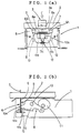
- Fig. 1(a) is a front view of an abnormality-in-stapling detecting mechanism of an electric stapler according to the present invention
- Fig. 1(b) is a side view of Fig. 1(a).
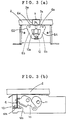
- Fig. 2(a) is a front view of the detecting mechanism which is working
- Fig. 2(b) is a side view of Fig. 2(a).
- Fig. 3(a) is a front view of the detecting mechanism which is working
- Fig. 3(b) is a side view of Fig. 3(a).
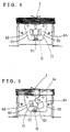
- Fig. 4 is an example showing how the detecting mechanism works when a staple is imperfectly driven into sheets of paper.
- Fig. 5 is another example showing how the detecting mechanism works when a staple is imperfectly driven into the sheets.
- Figs. 1(a) and 1(b) each show an abnormality-in-stapling detecting mechanism of an electric stapler.
- Reference numeral 1 designates a stapling base. Sheets 2 of paper to be fastened together are laid on the stapling base 1. In the stapling base 1, an opening 4 is formed for receiving the ends 3b of legs 3a of a staple 3 which have been driven through the sheets 2.
- a supporting plate 5 (not shown) is fixedly mounted under the opening 4. Shafts 7 are mounted on the supporting plate 5.
- a pair of movable clinchers 6A, 6B are rotatably attached to the shafts 7, 7, respectively.
- a driver 8 is disposed for rotating the clinchers 6A, 6B in predetermined directions (i.e., clockwise and counterclockwise, respectively).
- the clinchers 6A, 6B are each made up of a horizontal pressing part 6a situated under the opening 4 and a hook-shaped part 6b extending from the pressing part 6a downward.
- the clinchers 6A, 6B are each formed substantially C-shaped by the two parts 6a, 6b.
- the clinchers 6A, 6B are pulled toward each other by means of a spring 9.
- the clinchers 6A, 6B overlap at the ends 6c of the hook-shaped parts 6b.
- the pressing parts 6a are arranged such that the ends 3b of the legs 3a of the staple 3 are brought into contact with the respective surfaces of the pressing parts 6a when the legs 3a have been driven through the sheets 2.
- the driver 8 comprises a driving link 10 and a cam 11 rotated by a driving mechanism (not shown).
- the driving link 10 is rotated on a rotating shaft 13 mounted in the middle of the driving link 10, so that a front part 10a of the driving link 10 makes an up-and-down movement.
- the front part 10a of the driving link 10 is situated under the pressing parts 6a of the clinchers 6A, 6B, whereas a rear part 10b of the driving link 10 is engaged with an outer surface of the cam 11.
- the rotation of the cam 11 by the driving mechanism brings about the rotation of the driving link 10, thereby bringing about the up-and-down movement of the front part 10a of the driving link 10.
- a reciprocative driver, a driving unit for reciprocating the driver, a magazine for staples 3, etc., (each not shown) are mounted over the stapling base 1. According to the reciprocation of the driver, the staple 3 is driven into and through the sheets 2.
- a photosensor 12 is mounted under the opening 4 of the stapling base 1.
- the photosensor 12 comprises a light emitting diode 12a and a photodiode 12b which are arranged such that the ends 6c of the hook-shaped parts 6b of the clinchers 6A, 6B are placed between the light emitting diode 12a and the photodiode 12b.
- the photodiode 12b serves to receive a beam of light emitted by the light emitting diode 12a.
- the ends 6c of the hook-shaped parts 6b intercept the beam of light from the light emitting diode 12a.
- the driver 8 is actuated on the condition that the photodiode 12b has output a light-reception signal.
- the driver (not shown) is actuated and, as shown in Fig. 1(a), the legs 3a of the staple 3 are driven into the sheets 2.
- the ends 3b of the legs 3a enter the opening 4 and come in contact with the respective surfaces of the pressing parts 6a of the clinchers 6A, 6B so as to push the pressing parts 6a, as shown in Fig. 2(a).
- the clinchers 6A, 6B are rotated against the force of the spring 9 in a direction opposite to a predetermined direction.
- the clincher 6A in rotated counterclockwise whereas the clincher 6B is rotated clockwise.
- the photosensor 12 detects that the legs 3a have been normally driven through the sheets 2.
- the driver 8 is actuated to rotate the cam 11.
- the driving link 10 is rotated to move the front part 10a thereof upward as shown in Figs. 3(a) and 3(b) and thereby the clinchers 6A, 6B are each rotated in the predetermined direction.
- the clincher 6A is rotated clockwise whereas the clincher 6B is rotated counterclockwise. According to these rotations, the pressing parts 6a of the clinchers 6A, 6B are moved upward. Since the ends 3b of the legs 3a of the staple 3 are in contact with the surfaces of the pressing parts 6a, 6a, respectively, the ends 3b of the legs 3a are pressed and bent inward as the pressing parts 6a are moved upward. As a result, the ends 3b of the legs 3a are clinched, and the stapling is completed.
- the ends 6c of the hook-shaped parts 6b again intercept the beam of light emitted by the light emitting diode 12a. After that, the front part 10a of the driving link 10 returns to an initial position (shown in Figs. 1(a) and 1(b)) a little below the top dead point and, for next stapling, the clinchers 6A, 6B also return to an initial position shown in Figs. 1(a) and 1(b).
- both the clinchers 6A, 6B cannot be rotated or only one of the clinchers 6A, 6B can be rotated.
- at least one of the ends 6c of the clinchers 6A, 6B keeps intercepting the beam of light emitted by the light emitting diode 12a and accordingly the photosensor 12 does not detect that the legs 3a of the staple 3 have been normally driven through the sheets 2.
- the photosensor 12 may output a detection signal of normality in stapling after the photodiode 12b outputs a light-reception signal which shows that the legs 3a of the staple 3 has been normally driven through the sheets 2.
- the position of the photosensor 12 is not limited to that indicated above.
- a plurality of photosensors 12 may be disposed at places indicated by the broken lines in Fig. 1(a), respectively.
Landscapes
- Engineering & Computer Science (AREA)
- Mechanical Engineering (AREA)
- Life Sciences & Earth Sciences (AREA)
- Forests & Forestry (AREA)
- Portable Nailing Machines And Staplers (AREA)
- Dovetailed Work, And Nailing Machines And Stapling Machines For Wood (AREA)
Applications Claiming Priority (3)
| Application Number | Priority Date | Filing Date | Title |
|---|---|---|---|
| JP7039163A JP2923938B2 (ja) | 1995-02-03 | 1995-02-03 | ホッチキスにおける綴り異常検出機構 |
| JP39163/95 | 1995-02-03 | ||
| JP3916395 | 1995-02-03 |
Publications (2)
| Publication Number | Publication Date |
|---|---|
| EP0724936A1 true EP0724936A1 (fr) | 1996-08-07 |
| EP0724936B1 EP0724936B1 (fr) | 1999-11-03 |
Family
ID=12545462
Family Applications (1)
| Application Number | Title | Priority Date | Filing Date |
|---|---|---|---|
| EP96101513A Expired - Lifetime EP0724936B1 (fr) | 1995-02-03 | 1996-02-02 | Mécanisme de détection d'anomalie, pendant l'opération d'agrafage, pour une agrafeuse électrique |
Country Status (4)
| Country | Link |
|---|---|
| US (1) | US5678745A (fr) |
| EP (1) | EP0724936B1 (fr) |
| JP (1) | JP2923938B2 (fr) |
| DE (1) | DE69604939T2 (fr) |
Cited By (3)
| Publication number | Priority date | Publication date | Assignee | Title |
|---|---|---|---|---|
| EP1029643A1 (fr) * | 1999-02-15 | 2000-08-23 | Grapha-Holding Ag | Dispositif pour contrôler l' agrafage |
| EP1591272A1 (fr) * | 2004-04-26 | 2005-11-02 | Müller Martini Holding AG | Vérification de la qualité d'une agrafe de produits imprimés |
| WO2008076036A1 (fr) * | 2006-12-21 | 2008-06-26 | Isaberg Rapid Ab | Agrafeuse |
Families Citing this family (12)
| Publication number | Priority date | Publication date | Assignee | Title |
|---|---|---|---|---|
| DE19607296A1 (de) * | 1996-02-27 | 1997-08-28 | Kodak Ag | Heftvorrichtung zum Zusammenheften von Blättern |
| US6925849B2 (en) * | 2002-09-10 | 2005-08-09 | Acco Brands, Inc. | Stapler anvil |
| WO2005068135A1 (fr) * | 2004-01-13 | 2005-07-28 | Max Co., Ltd. | Agrafeuse |
| SE0400223L (sv) * | 2004-02-05 | 2005-02-15 | Isaberg Rapid Ab | Häftapparat med spärrarrangemang |
| US7334716B2 (en) * | 2005-01-26 | 2008-02-26 | Apex Mfg. Co., Ltd. | Stapler capable of cutting staple legs one after another |
| US20070023474A1 (en) * | 2005-07-14 | 2007-02-01 | Smith Robert S | Clincher for a heavy duty stapler |
| JP5359694B2 (ja) * | 2008-10-17 | 2013-12-04 | マックス株式会社 | ステープラのクリンチャ機構 |
| EP2255935B1 (fr) * | 2009-05-28 | 2012-06-20 | Max Co., Ltd. | Agrafeuse électrique |
| US9987734B2 (en) | 2013-01-23 | 2018-06-05 | Worktools, Inc. | Flat clinch anvil assembly |
| US9592597B2 (en) | 2013-01-23 | 2017-03-14 | Worktools, Inc. | Flat clinch stapler anvil assembly |
| DE102019128704A1 (de) * | 2019-10-24 | 2021-04-29 | Isaberg Rapid Ab | Heftklammergerät |
| US11148270B2 (en) * | 2019-12-17 | 2021-10-19 | Apex Mfg. Co., Ltd. | Stapler |
Citations (8)
| Publication number | Priority date | Publication date | Assignee | Title |
|---|---|---|---|---|
| UST958003I4 (en) * | 1976-03-30 | 1977-05-03 | Staple sensing apparatus | |
| US4318555A (en) * | 1980-01-15 | 1982-03-09 | Eastman Kodak Company | Stapler |
| US4549087A (en) * | 1982-12-27 | 1985-10-22 | Usm Corporation | Lead sensing system |
| EP0200485A2 (fr) * | 1985-05-01 | 1986-11-05 | The Interlake Companies, Inc. | Dispositif de pliage chevauché pour machine â agrafer |
| DE3805784A1 (de) * | 1987-02-24 | 1988-09-08 | Alliance Automation Systems | Biegevorrichtung zum biegen der anschlussleitungen von bauelementen auf leiterplatten |
| US5094379A (en) * | 1991-01-25 | 1992-03-10 | Xerox Corporation | Copier with on-line and convenience staplers with shared power supply |
| US5230457A (en) * | 1987-11-16 | 1993-07-27 | Canon Kabushiki Kaisha | Sheet stapler |
| EP0612594A1 (fr) * | 1993-02-10 | 1994-08-31 | Max Co., Ltd. | Agrafeuse entraînée par un moteur |
Family Cites Families (7)
| Publication number | Priority date | Publication date | Assignee | Title |
|---|---|---|---|---|
| JPS58173629A (ja) * | 1982-04-06 | 1983-10-12 | Taigaasu Polymer Kk | ホ−スの製造方法及びその装置 |
| US4546910A (en) * | 1982-07-07 | 1985-10-15 | Xerox Corporation | Active clinchers and wire stitchers incorporating same |
| JPS6064802A (ja) * | 1983-09-20 | 1985-04-13 | キヤノン株式会社 | ステツプル打込みミス検知装置 |
| JPS6399904A (ja) * | 1986-10-16 | 1988-05-02 | マックス株式会社 | ホツチキスのステ−プル脚切断駆動装置 |
| US5133493A (en) * | 1990-11-01 | 1992-07-28 | Eastman Kodak Company | Stapling system having noise reducing work clamp |
| SE500140C2 (sv) * | 1992-06-30 | 1994-04-25 | Isaberg Ab | Häftapparat med flatläggningsmekanism |
| US5586710A (en) * | 1992-11-13 | 1996-12-24 | Roll Systems, Inc. | Power stapler |
-
1995
- 1995-02-03 JP JP7039163A patent/JP2923938B2/ja not_active Expired - Fee Related
-
1996
- 1996-02-02 EP EP96101513A patent/EP0724936B1/fr not_active Expired - Lifetime
- 1996-02-02 DE DE69604939T patent/DE69604939T2/de not_active Expired - Fee Related
- 1996-02-05 US US08/596,582 patent/US5678745A/en not_active Expired - Lifetime
Patent Citations (9)
| Publication number | Priority date | Publication date | Assignee | Title |
|---|---|---|---|---|
| UST958003I4 (en) * | 1976-03-30 | 1977-05-03 | Staple sensing apparatus | |
| US4318555A (en) * | 1980-01-15 | 1982-03-09 | Eastman Kodak Company | Stapler |
| US4549087A (en) * | 1982-12-27 | 1985-10-22 | Usm Corporation | Lead sensing system |
| US4549087B1 (fr) * | 1982-12-27 | 1988-11-08 | ||
| EP0200485A2 (fr) * | 1985-05-01 | 1986-11-05 | The Interlake Companies, Inc. | Dispositif de pliage chevauché pour machine â agrafer |
| DE3805784A1 (de) * | 1987-02-24 | 1988-09-08 | Alliance Automation Systems | Biegevorrichtung zum biegen der anschlussleitungen von bauelementen auf leiterplatten |
| US5230457A (en) * | 1987-11-16 | 1993-07-27 | Canon Kabushiki Kaisha | Sheet stapler |
| US5094379A (en) * | 1991-01-25 | 1992-03-10 | Xerox Corporation | Copier with on-line and convenience staplers with shared power supply |
| EP0612594A1 (fr) * | 1993-02-10 | 1994-08-31 | Max Co., Ltd. | Agrafeuse entraînée par un moteur |
Cited By (5)
| Publication number | Priority date | Publication date | Assignee | Title |
|---|---|---|---|---|
| EP1029643A1 (fr) * | 1999-02-15 | 2000-08-23 | Grapha-Holding Ag | Dispositif pour contrôler l' agrafage |
| EP1591272A1 (fr) * | 2004-04-26 | 2005-11-02 | Müller Martini Holding AG | Vérification de la qualité d'une agrafe de produits imprimés |
| US7194892B2 (en) | 2004-04-26 | 2007-03-27 | Müller Martini Holding AG | Method and device for monitoring wire staples applied to print products by a wire-stitching machine |
| WO2008076036A1 (fr) * | 2006-12-21 | 2008-06-26 | Isaberg Rapid Ab | Agrafeuse |
| US8579173B2 (en) | 2006-12-21 | 2013-11-12 | Isaberg Rapid Ab | Stapler |
Also Published As
| Publication number | Publication date |
|---|---|
| DE69604939T2 (de) | 2000-02-17 |
| DE69604939D1 (de) | 1999-12-09 |
| JP2923938B2 (ja) | 1999-07-26 |
| JPH08206975A (ja) | 1996-08-13 |
| EP0724936B1 (fr) | 1999-11-03 |
| US5678745A (en) | 1997-10-21 |
Similar Documents
| Publication | Publication Date | Title |
|---|---|---|
| US5678745A (en) | Abnormality-in-stapling detecting mechanism of electric stapler | |
| US7048165B2 (en) | Staple detecting mechanism of electric stapler | |
| US5230457A (en) | Sheet stapler | |
| USRE36923E (en) | Sheet stapler | |
| US5573233A (en) | Sheet post-processing apparatus with malfunction operation | |
| EP1136207A1 (fr) | Agrafeuse | |
| EP1136208B1 (fr) | Agrafeuse | |
| EP2255935B1 (fr) | Agrafeuse électrique | |
| JP4078924B2 (ja) | 電動ステープラー | |
| US10870215B2 (en) | Staple cartridge and stapler | |
| EP0920963B1 (fr) | Dispositif d'agrafage | |
| EP0485846B1 (fr) | Machine pour agrafage de feuilles | |
| JP5233843B2 (ja) | 電動ステープラ | |
| CN103056935A (zh) | 电动订书机 | |
| JP3094881B2 (ja) | 電動ホッチキス | |
| JPH0626800B2 (ja) | シート綴じ装置 | |
| JPH058580A (ja) | シート綴じ装置 | |
| JP3211632B2 (ja) | 電動ステープラ | |
| JP3534365B2 (ja) | 電動ステープラ | |
| JPH01146674A (ja) | シート綴じ装置 | |
| JPH02125702A (ja) | シート分類綴じ装置 | |
| JPH0994770A (ja) | 電動ホッチキスにおけるドライバプレートの待機位置検出機構 |
Legal Events
| Date | Code | Title | Description |
|---|---|---|---|
| PUAI | Public reference made under article 153(3) epc to a published international application that has entered the european phase |
Free format text: ORIGINAL CODE: 0009012 |
|
| AK | Designated contracting states |
Kind code of ref document: A1 Designated state(s): DE FR GB NL |
|
| 17P | Request for examination filed |
Effective date: 19960815 |
|
| 17Q | First examination report despatched |
Effective date: 19980213 |
|
| GRAG | Despatch of communication of intention to grant |
Free format text: ORIGINAL CODE: EPIDOS AGRA |
|
| GRAG | Despatch of communication of intention to grant |
Free format text: ORIGINAL CODE: EPIDOS AGRA |
|
| GRAH | Despatch of communication of intention to grant a patent |
Free format text: ORIGINAL CODE: EPIDOS IGRA |
|
| GRAH | Despatch of communication of intention to grant a patent |
Free format text: ORIGINAL CODE: EPIDOS IGRA |
|
| GRAA | (expected) grant |
Free format text: ORIGINAL CODE: 0009210 |
|
| AK | Designated contracting states |
Kind code of ref document: B1 Designated state(s): DE FR GB NL |
|
| REF | Corresponds to: |
Ref document number: 69604939 Country of ref document: DE Date of ref document: 19991209 |
|
| ET | Fr: translation filed | ||
| PLBE | No opposition filed within time limit |
Free format text: ORIGINAL CODE: 0009261 |
|
| STAA | Information on the status of an ep patent application or granted ep patent |
Free format text: STATUS: NO OPPOSITION FILED WITHIN TIME LIMIT |
|
| 26N | No opposition filed | ||
| REG | Reference to a national code |
Ref country code: GB Ref legal event code: IF02 |
|
| PGFP | Annual fee paid to national office [announced via postgrant information from national office to epo] |
Ref country code: NL Payment date: 20070131 Year of fee payment: 12 |
|
| PGFP | Annual fee paid to national office [announced via postgrant information from national office to epo] |
Ref country code: GB Payment date: 20070219 Year of fee payment: 12 |
|
| PGFP | Annual fee paid to national office [announced via postgrant information from national office to epo] |
Ref country code: DE Payment date: 20070227 Year of fee payment: 12 |
|
| PGFP | Annual fee paid to national office [announced via postgrant information from national office to epo] |
Ref country code: FR Payment date: 20070223 Year of fee payment: 12 |
|
| GBPC | Gb: european patent ceased through non-payment of renewal fee |
Effective date: 20080202 |
|
| NLV4 | Nl: lapsed or anulled due to non-payment of the annual fee |
Effective date: 20080901 |
|
| PG25 | Lapsed in a contracting state [announced via postgrant information from national office to epo] |
Ref country code: NL Free format text: LAPSE BECAUSE OF NON-PAYMENT OF DUE FEES Effective date: 20080901 |
|
| REG | Reference to a national code |
Ref country code: FR Ref legal event code: ST Effective date: 20081031 |
|
| PG25 | Lapsed in a contracting state [announced via postgrant information from national office to epo] |
Ref country code: DE Free format text: LAPSE BECAUSE OF NON-PAYMENT OF DUE FEES Effective date: 20080902 |
|
| PG25 | Lapsed in a contracting state [announced via postgrant information from national office to epo] |
Ref country code: FR Free format text: LAPSE BECAUSE OF NON-PAYMENT OF DUE FEES Effective date: 20080229 |
|
| PG25 | Lapsed in a contracting state [announced via postgrant information from national office to epo] |
Ref country code: GB Free format text: LAPSE BECAUSE OF NON-PAYMENT OF DUE FEES Effective date: 20080202 |