EP0724958B2 - Machine d'impression avec des organes demontables - Google Patents
Machine d'impression avec des organes demontables Download PDFInfo
- Publication number
- EP0724958B2 EP0724958B2 EP96100422A EP96100422A EP0724958B2 EP 0724958 B2 EP0724958 B2 EP 0724958B2 EP 96100422 A EP96100422 A EP 96100422A EP 96100422 A EP96100422 A EP 96100422A EP 0724958 B2 EP0724958 B2 EP 0724958B2
- Authority
- EP
- European Patent Office
- Prior art keywords
- sensor
- magnetic field
- printing press
- component
- evaluation unit
- Prior art date
- Legal status (The legal status is an assumption and is not a legal conclusion. Google has not performed a legal analysis and makes no representation as to the accuracy of the status listed.)
- Expired - Lifetime
Links
Images


Classifications
-
- B—PERFORMING OPERATIONS; TRANSPORTING
- B41—PRINTING; LINING MACHINES; TYPEWRITERS; STAMPS
- B41F—PRINTING MACHINES OR PRESSES
- B41F33/00—Indicating, counting, warning, control or safety devices
- B41F33/0018—Protection means against injury to the operator
-
- B—PERFORMING OPERATIONS; TRANSPORTING
- B41—PRINTING; LINING MACHINES; TYPEWRITERS; STAMPS
- B41F—PRINTING MACHINES OR PRESSES
- B41F33/00—Indicating, counting, warning, control or safety devices
-
- B—PERFORMING OPERATIONS; TRANSPORTING
- B41—PRINTING; LINING MACHINES; TYPEWRITERS; STAMPS
- B41P—INDEXING SCHEME RELATING TO PRINTING, LINING MACHINES, TYPEWRITERS, AND TO STAMPS
- B41P2233/00—Arrangements for the operation of printing presses
- B41P2233/20—Safety devices preventing damage
Definitions
- the invention relates to a printing machine with removable Components according to the generic term of Claim 1 or 2.
- Printing machines in particular sheetfed offset printing machines often show a variety of or replaceable components as examples for removable and / or replaceable components here are the ink / dampening medium rollers Inking / dampening units, dosing devices for inking units, Dampening units, painting equipment additional or interchangeable according to the properties of the substrate Sheet guiding devices for sheet feeding, sheet storage and the like called.
- From DE 42 40 487 C1 is a roller bearing known for inking, dampening or coating unit rollers, which the corresponding roller removably receives.
- From DE 43 24 631 A1 and DE 43 34 803 C1 are dosing and application devices for fluid media of different viscosities are preferred different types of paint known, either a metering roller with an applicator roller (low viscosity Media) or a chambered doctor blade with a screened Applicator roller (higher viscosity media) interacts.
- the components mentioned can be removed between the Side frame walls of the printing unit arranged
- a disadvantage of printing machines with removable components is that in particular from a machine control center it is not recognizable that the corresponding component is missing.
- dampening or coating roller cause significant malfunctions.
- a coating unit of the type mentioned above Chamber doctor blade in addition to the screened application roller against a metering roller and one with a smooth surface provided and forgotten insert the metering roller into the corresponding bearings, this is how it happens with an automatic paint supply to a significant contamination of the underlying Machine parts, especially those that carry the bow Elements. Used in an inking or dampening system one roller is taken around this against another do not accidentally replace them in the appropriate storage inserted, so it happens in this case to significant operational disruptions, since the Ink and / or fountain solution flow disturbed if not is even made impossible. It should also be noted that when certain components are removed Machine or even personal injury cannot be excluded are.
- NL-A-8202104 is a device for Acquisition of the angle creation of cylinders / rollers a printing machine known
- the cylinders / rollers have a permanent magnet eccentric to their axis on, the frame fixed by the Magnet switchable sensor in the form of a reed contact assigned.
- EP 0 623 539 A1 describes a printing press with a removable cassette known for receiving printer paper.
- the feeder has the position the sensor that detects the cassette with a downstream evaluation unit. This is the Provide the cassette with a magnet that attaches it to the evaluation unit connected reed contact interacts. One is carried out by the evaluation unit Switching status query.
- the object of the present invention is a printing press according to the preamble of claim 1 or 2 to expand such that with simple means can be determined whether a component is installed or not.
- the invention is detailed on a removable Roller of an inking, dampening or coating unit described.
- the invention Principle can also be use with a removable chambered doctor blade.
- a permanent magnet attached corresponding to the frame fixed the position of the permanent magnet in the installed state of the chamber doctor blade a magnetic field detecting sensor is assigned. That way can also be used with other removable components provided a permanent magnet, corresponding to them a simple, inexpensive sensor assigned becomes.
- a removable chamber doctor blade at least two permanent magnets lying close together are attached.
- These permanent magnets are by a frame-fixed sensor, the for example has two reed contacts connected in series, queried. There is preferably another one Evaluation of the switching status of the reed contacts within a short time interval so that the Correct installation state of the chamber doctor blade in a safety-relevant Way is noticeable.
- a roller 1 of an inking, dampening or coating unit has a pin 2 at each of its two ends on which an annular bearing 4 is placed is.
- Fig. 1 shows the one end of the roller 1 with a pin 2 and a bearing 4.
- the pin 2 is with the attached bearing 4 in one up open, U-shaped bearing shell 5 inserted, which in turn on a side frame wall 6 of the pressure or Coating unit is attached. So far based on that The bearing arrangement described in Fig. 1 is on the opposite side frame wall, not shown here corresponding.
- Fig. 1 is at one End wall of the pin 2 in the center of the roller 1 Permanent magnet 3 flat to the surface of this end wall embedded in a corresponding recess.
- a corresponding hole 7 of the U-shaped Bearing shell 5 is also coaxial to the axis the roller 1 in the installed state, the magnetic field of the permanent magnet 3 detecting sensor 8 embedded.
- the U-shaped bearing cup that is open at the top 5, the roller 1 is removable upwards.
- the permanent magnet 3 of the measuring field surface of the sensor 8 opposite, so that a signal can be removed.
- the sensor 8 can be a suitable, act as a magnetic field detecting sensor, for example in a simple form around a reed contact or a sensor that is based on the magnetoresistive Principle works. If the roller 1 removed, so the sensor 8 can not Magnetic field can be detected, so that the dismantled state of the roller 1 can be determined.
- Lead wires of the sensor 8 is on the Roller 1 facing away from the rear of the U-shaped bearing shell 5 incorporated a groove 9, which according to Art of a stitch opens into hole 7.
- the sensor 8 can preferably be designed in the manner of a tube sensor, i.e. made cylindrical and with a External thread. Then it is appropriate provide the bore 7 with a thread so that the Sensor 8 is simply screwed into this bore 7.
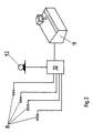
- each sensor 8 can be queried individually with the evaluation unit 10 connected.
- the evaluation unit 10 is also available in operative connection with a control station 11 for control the printing machine, not shown.
- the evaluation unit 10 is designed to be just then Generate signal if one of the sensors 8 no Receives signal from a permanent magnet, that is corresponding component is not installed.
- About the indicated display device of the control center 1 in The form of a monitor can thus be displayed, which of the Sensors 8 receives no signal, which component especially in which printing unit is missing.
- FIG. 2 shows that the evaluation unit 10 further with the electric drive 12 not shown printing press is in operative connection.
- Those sensors 8 that are particularly security or functionally relevant components can be assigned then blocking via the evaluation unit 10 of the drive 12 against a start of the not shown Initiate printing press. It happens also via the control center display 11 to play a corresponding error message along with an indication of which component is missing.
- Fig. 3 shows an arrangement for querying a Chamber doctor blade 13.
- two permanent magnets 3 are embedded on the front, each of which has a pole face flat with the housing surface completes.
- On a frame wall, not shown of the coating unit is the permanent magnet opposite a sensor 8 attached, which as indicated, two reed contacts 14 inside through the two permanent magnets 3 when correct Installation position of the chambered doctor blade 13 can be switched separately having.
- the sensor is connected to the evaluation unit 10, which the switching state of the reed contacts 14 preferably within a short time interval queries.
Landscapes
- Inking, Control Or Cleaning Of Printing Machines (AREA)
- Rotary Presses (AREA)
- Ink Jet (AREA)
- Developing Agents For Electrophotography (AREA)
Claims (6)
- Machine d'impression, en particulier machine d'impression offset à feuilles, qui comporte des éléments amovibles, comme des rouleaux, des dispositifs d'amenée, de dosage et d'application, au moins un capteur détectant la position de l'élément et comportant une unité d'évaluation montée en aval étant prévu, l'élément amovible comportant au moins un dispositif engendrant un champ magnétique permanent, auquel est associé de façon fixée au bâti et de façon correspondant à la position du dispositif engendrant le champ magnétique dans la position montée de l'élément amovible, au moins un capteur détectant le champ magnétique et raccordé à l'unité d'évaluation, et par l'unité d'évaluation, une interrogation de l'état de commutation du au moins un capteur étant réalisée en fonction d'une sélection fonctionnelle conditionnant l'élément,
caractérisée en ce que l'élément amovible est un rouleau (1) d'une unité d'encrage, de mouillage ou de laquage, qui comporte au centre de la paroi frontale d'un tourillon (2), de façon alignée superficiellement avec la face frontale, un dispositif (3) encastré et engendrant un champ magnétique, et le capteur (8) est agencé, coaxialement à l'axe du rouleau (1), de façon fixée au bâti, et dans l'état monté de façon opposée à la face frontale du tourillon (2) du rouleau (1). - Machine d'impression, en particulier machine d'impression offset à feuilles, qui comporte des éléments amovibles, comme des rouleaux, des dispositifs d'amenée, de dosage et d'application, au moins un capteur détectant la position de l'élément et comportant une unité d'évaluation montée en aval étant prévu, l'élément amovible comportant au moins un dispositif engendrant un champ magnétique permanent, auquel est associé de façon fixée au bâti et de façon correspondant à la position du dispositif engendrant le champ magnétique dans la position montée de l'élément amovible, au moins un capteur détectant le champ magnétique et raccordé à l'unité d'évaluation, et par l'unité d'évaluation, une interrogation de l'état de commutation du au moins un capteur étant réalisée en fonction d'une sélection fonctionnelle conditionnant l'élément,
caractérisée en ce que, sur un racloir de chambre (13) pouvant être enlevé de la machine, sont agencés au moins deux dispositifs (3) engendrant un champ magnétique, auxquels sont associés des capteurs (8) agencés en nombre correspondant et fixés au bâti. - Machine d'impression selon la revendication 1,
caractérisée en ce que le dispositif engendrant le champ magnétique est un aimant permanent (3). - Machine d'impression selon la revendication 1,
caractérisée en ce que le capteur (8) est agencé dans une coquille de support (5), en forme de U, recevant le rouleau (1) par l'intermédiaire d'un tourillon (2). - Machine d'impression selon la revendication 4,
caractérisée en ce que le capteur (8) est encastré dans un perçage (7) de la coquille de support (5) en forme de U. - Machine d'impression selon la revendication 2,
caractérisée en ce que, pour plusieurs dispositifs (3) agencés les uns à côté des autres et engendrant un champ magnétique, un nombre correspondant de contacts Reed (14) sont agencés dans un capteur (8).
Applications Claiming Priority (2)
| Application Number | Priority Date | Filing Date | Title |
|---|---|---|---|
| DE19503695A DE19503695C2 (de) | 1995-02-04 | 1995-02-04 | Absicherung für eine Druckmaschine |
| DE19503695 | 1995-02-04 |
Publications (3)
| Publication Number | Publication Date |
|---|---|
| EP0724958A1 EP0724958A1 (fr) | 1996-08-07 |
| EP0724958B1 EP0724958B1 (fr) | 1998-08-12 |
| EP0724958B2 true EP0724958B2 (fr) | 2001-05-02 |
Family
ID=7753191
Family Applications (1)
| Application Number | Title | Priority Date | Filing Date |
|---|---|---|---|
| EP96100422A Expired - Lifetime EP0724958B2 (fr) | 1995-02-04 | 1996-01-12 | Machine d'impression avec des organes demontables |
Country Status (5)
| Country | Link |
|---|---|
| US (1) | US5787813A (fr) |
| EP (1) | EP0724958B2 (fr) |
| JP (1) | JP2771504B2 (fr) |
| AT (1) | ATE169563T1 (fr) |
| DE (2) | DE19503695C2 (fr) |
Families Citing this family (10)
| Publication number | Priority date | Publication date | Assignee | Title |
|---|---|---|---|---|
| DE19643984B4 (de) * | 1996-10-31 | 2005-01-05 | Man Roland Druckmaschinen Ag | Funktionssteuerung für eine Dosiereinrichtung |
| DE29813976U1 (de) * | 1998-08-05 | 1998-10-08 | MAN Roland Druckmaschinen AG, 63075 Offenbach | Einrichtung zur Zustandsanzeige einer Druckmaschine |
| EP1173883B1 (fr) * | 1999-04-27 | 2003-10-01 | Gebrüder Decker GmbH & Co. Kg | Dispositif de traitement pour des tranches de silicium |
| FI116481B (fi) * | 2000-04-13 | 2005-11-30 | Metso Paper Inc | Komposiittirakenteinen tela ja menetelmä sen valmistamiseksi |
| US6530319B1 (en) * | 2001-09-10 | 2003-03-11 | Ward Holding Company, Inc. | Quick change ink roll |
| US6796238B2 (en) * | 2002-09-09 | 2004-09-28 | Delaware Capital Formation, Inc. | Plate roll loading and positioning apparatus and method |
| DE102004002660B4 (de) * | 2003-01-31 | 2013-06-13 | Heidelberger Druckmaschinen Ag | Verfahren zum Betreiben einer Bogendruckmaschine und Bogendruckmaschine zur Durchführung dieses Verfahrens |
| JP2007030349A (ja) * | 2005-07-27 | 2007-02-08 | Komori Corp | 印刷機の異常状態表示方法および装置 |
| US7814898B2 (en) * | 2005-08-08 | 2010-10-19 | Snow Dragon Llc | High capacity snow melting apparatus and method |
| DE102017118927A1 (de) * | 2017-07-03 | 2019-01-03 | Weber Maschinenbau Gmbh Breidenbach | Bereitstellen von bahnförmigem Zwischenblattmaterial an einem Schneidbereich |
Citations (4)
| Publication number | Priority date | Publication date | Assignee | Title |
|---|---|---|---|---|
| US5025726A (en) † | 1990-02-27 | 1991-06-25 | Komori Corporation | Movable inker type printing machine |
| DE4213662A1 (de) † | 1992-04-25 | 1993-10-28 | Koenig & Bauer Ag | Verfahren zum Anstellen einer Kammerrakel an eine farbabgebende Walze und Vorrichtung zur Durchführung des Verfahrens |
| EP0581056A1 (fr) † | 1992-07-30 | 1994-02-02 | Heidelberger Druckmaschinen Aktiengesellschaft | Dispositif d'identification de revêtements flexibles de cylindres |
| EP0623539A1 (fr) † | 1993-03-16 | 1994-11-09 | Riso Kagaku Corporation | Dispositif d'alimentation en feuilles pour appareil de formation d'images |
Family Cites Families (11)
| Publication number | Priority date | Publication date | Assignee | Title |
|---|---|---|---|---|
| US4231292A (en) * | 1978-08-25 | 1980-11-04 | White Consolidated Industries, Inc. | Safety interlock for offset printing press |
| CS222747B1 (en) * | 1981-05-25 | 1983-07-29 | Miroslav Kolombu | Device for raporting rotary templates mainly on the machines for printing the textiles |
| DE3315445A1 (de) * | 1983-04-28 | 1984-10-31 | M.A.N.- Roland Druckmaschinen AG, 6050 Offenbach | Absicherung der umstellung |
| US4646042A (en) * | 1985-02-08 | 1987-02-24 | Hi-Stat Manufacturing Co., Inc. | Speed and distance sensor |
| JPH043805Y2 (fr) * | 1985-04-12 | 1992-02-05 | ||
| DE3734525A1 (de) * | 1987-10-13 | 1989-04-27 | Festo Kg | Insbesondere in abhaengigkeit von bestimmten kolbenstellungen eines kolben-zylinder-aggregates betaetigbare schaltanordnung |
| CH675628A5 (fr) * | 1988-06-20 | 1990-10-15 | Forster Ag Hermann | |
| DE4240487C1 (de) * | 1992-12-02 | 1993-12-09 | Roland Man Druckmasch | Walzenlagerung |
| JP3292535B2 (ja) * | 1993-03-01 | 2002-06-17 | 理想科学工業株式会社 | 孔版印刷装置および版胴 |
| DE4324631C2 (de) * | 1993-07-22 | 1996-09-19 | Roland Man Druckmasch | Einrichtung zum Aufbringen flüssiger Medien auf einen Bedruckstoff in Offsetdruckmaschinen |
| DE4334803C1 (de) * | 1993-10-13 | 1994-11-03 | Roland Man Druckmasch | Einrichtung zum Dosieren flüssiger Medien in Offsetdruckmaschinen, vorzugsweise für Lackiereinheiten |
-
1995
- 1995-02-04 DE DE19503695A patent/DE19503695C2/de not_active Expired - Lifetime
-
1996
- 1996-01-12 EP EP96100422A patent/EP0724958B2/fr not_active Expired - Lifetime
- 1996-01-12 AT AT96100422T patent/ATE169563T1/de not_active IP Right Cessation
- 1996-01-12 DE DE59600407T patent/DE59600407D1/de not_active Expired - Lifetime
- 1996-01-31 JP JP8015421A patent/JP2771504B2/ja not_active Expired - Fee Related
- 1996-02-02 US US08/597,464 patent/US5787813A/en not_active Expired - Fee Related
Patent Citations (4)
| Publication number | Priority date | Publication date | Assignee | Title |
|---|---|---|---|---|
| US5025726A (en) † | 1990-02-27 | 1991-06-25 | Komori Corporation | Movable inker type printing machine |
| DE4213662A1 (de) † | 1992-04-25 | 1993-10-28 | Koenig & Bauer Ag | Verfahren zum Anstellen einer Kammerrakel an eine farbabgebende Walze und Vorrichtung zur Durchführung des Verfahrens |
| EP0581056A1 (fr) † | 1992-07-30 | 1994-02-02 | Heidelberger Druckmaschinen Aktiengesellschaft | Dispositif d'identification de revêtements flexibles de cylindres |
| EP0623539A1 (fr) † | 1993-03-16 | 1994-11-09 | Riso Kagaku Corporation | Dispositif d'alimentation en feuilles pour appareil de formation d'images |
Also Published As
| Publication number | Publication date |
|---|---|
| DE19503695A1 (de) | 1996-08-08 |
| ATE169563T1 (de) | 1998-08-15 |
| DE19503695C2 (de) | 1997-02-27 |
| EP0724958B1 (fr) | 1998-08-12 |
| JPH08252907A (ja) | 1996-10-01 |
| JP2771504B2 (ja) | 1998-07-02 |
| US5787813A (en) | 1998-08-04 |
| DE59600407D1 (de) | 1998-09-17 |
| EP0724958A1 (fr) | 1996-08-07 |
Similar Documents
| Publication | Publication Date | Title |
|---|---|---|
| EP0549936B1 (fr) | Cylindre de transfert avec manchon échangeable, supporté entre deux parois latérales d'un élément d'impression | |
| EP0724958B2 (fr) | Machine d'impression avec des organes demontables | |
| EP3173241A2 (fr) | Procédé de détection de fuite d'encre dans une imprimante à jet d'encre | |
| DE10111068B4 (de) | Walzenschloss zum lösbaren Befestigen einer Walze in einer Druckmaschine | |
| EP0764524A2 (fr) | Dispositif d'encrage court | |
| EP0929401B1 (fr) | Unite vis de reglage d'encrier pour spatule d'encrier dans une presse a imprimer | |
| CH686821A5 (de) | Farbwerk mit einendig gelagerter Rasterwalze sowie mit einendig gelagertem Formatzylinder. | |
| DE102005016309B4 (de) | Bogendruckmaschine | |
| DE9004130U1 (de) | Vorrichtung zum Spannen von Platten auf einen Formzylinder einer Rotationsdruckmaschine | |
| DE69712571T2 (de) | Verfahren zum Reinigen eines Gummituchzylinders in einer Druckmachine | |
| EP0210671A2 (fr) | Dispositif de mouillage pour machine à imprimer | |
| CH654524A5 (en) | Printing machine having a plurality of forme cylinders assigned to a central impression cylinder | |
| DE2725725A1 (de) | Flachoffsetpresse | |
| EP1961560B1 (fr) | Procédé destiné au fonctionnement d'une machine de traitement | |
| DE3908043C1 (fr) | ||
| EP1075650B1 (fr) | Dispositif et methode pour mesurer l'adhesivite d'une substance coulante | |
| EP1099554B1 (fr) | Bande de nettoyage pour un cylindre de la presse et dispositif de nettoyage | |
| EP1270220B1 (fr) | Dispositif pour échanger des rouleaux ou cylindres dans une machine à imprimer | |
| DE3024758C2 (de) | Bogen-Offsetdruckmaschine für Schön- und Widerdruck | |
| EP1752287B1 (fr) | Machine d'impression sur feuilles et son procédé | |
| DE102004006943A1 (de) | Einrichtung zur Registerkorrektur von Druckplatten | |
| EP1106350B1 (fr) | Dispositif pour imprimer de feuilles recto-verso dans de machines d'impression offset à feuille | |
| DE29913379U1 (de) | Einrichtung zum Dosieren eines flüssigen Mediums in einer Druckmaschine | |
| DE102006055302B4 (de) | Verfahren zur Selektion von Bedruckstoffen in einer Druckmaschine | |
| DE19520918A1 (de) | Steuerung für eine Druckmaschine |
Legal Events
| Date | Code | Title | Description |
|---|---|---|---|
| PUAI | Public reference made under article 153(3) epc to a published international application that has entered the european phase |
Free format text: ORIGINAL CODE: 0009012 |
|
| 17P | Request for examination filed |
Effective date: 19960124 |
|
| AK | Designated contracting states |
Kind code of ref document: A1 Designated state(s): AT BE CH DE FR GB IT LI NL SE |
|
| 17Q | First examination report despatched |
Effective date: 19970127 |
|
| GRAG | Despatch of communication of intention to grant |
Free format text: ORIGINAL CODE: EPIDOS AGRA |
|
| GRAG | Despatch of communication of intention to grant |
Free format text: ORIGINAL CODE: EPIDOS AGRA |
|
| GRAH | Despatch of communication of intention to grant a patent |
Free format text: ORIGINAL CODE: EPIDOS IGRA |
|
| GRAH | Despatch of communication of intention to grant a patent |
Free format text: ORIGINAL CODE: EPIDOS IGRA |
|
| ITF | It: translation for a ep patent filed | ||
| GRAA | (expected) grant |
Free format text: ORIGINAL CODE: 0009210 |
|
| AK | Designated contracting states |
Kind code of ref document: B1 Designated state(s): AT BE CH DE FR GB IT LI NL SE |
|
| PG25 | Lapsed in a contracting state [announced via postgrant information from national office to epo] |
Ref country code: NL Free format text: LAPSE BECAUSE OF FAILURE TO SUBMIT A TRANSLATION OF THE DESCRIPTION OR TO PAY THE FEE WITHIN THE PRESCRIBED TIME-LIMIT Effective date: 19980812 |
|
| REF | Corresponds to: |
Ref document number: 169563 Country of ref document: AT Date of ref document: 19980815 Kind code of ref document: T |
|
| REG | Reference to a national code |
Ref country code: CH Ref legal event code: NV Representative=s name: E. BLUM & CO. PATENTANWAELTE Ref country code: CH Ref legal event code: EP |
|
| ET | Fr: translation filed | ||
| GBT | Gb: translation of ep patent filed (gb section 77(6)(a)/1977) |
Effective date: 19980814 |
|
| REF | Corresponds to: |
Ref document number: 59600407 Country of ref document: DE Date of ref document: 19980917 |
|
| PG25 | Lapsed in a contracting state [announced via postgrant information from national office to epo] |
Ref country code: SE Free format text: LAPSE BECAUSE OF FAILURE TO SUBMIT A TRANSLATION OF THE DESCRIPTION OR TO PAY THE FEE WITHIN THE PRESCRIBED TIME-LIMIT Effective date: 19981112 |
|
| PG25 | Lapsed in a contracting state [announced via postgrant information from national office to epo] |
Ref country code: BE Free format text: LAPSE BECAUSE OF NON-PAYMENT OF DUE FEES Effective date: 19990131 |
|
| NLV1 | Nl: lapsed or annulled due to failure to fulfill the requirements of art. 29p and 29m of the patents act | ||
| PLBI | Opposition filed |
Free format text: ORIGINAL CODE: 0009260 |
|
| PLBF | Reply of patent proprietor to notice(s) of opposition |
Free format text: ORIGINAL CODE: EPIDOS OBSO |
|
| 26 | Opposition filed |
Opponent name: KOENIG & BAUER AG Effective date: 19990511 |
|
| BERE | Be: lapsed |
Owner name: MAN ROLAND DRUCKMASCHINEN A.G. Effective date: 19990131 |
|
| PLBF | Reply of patent proprietor to notice(s) of opposition |
Free format text: ORIGINAL CODE: EPIDOS OBSO |
|
| PLAW | Interlocutory decision in opposition |
Free format text: ORIGINAL CODE: EPIDOS IDOP |
|
| PLAW | Interlocutory decision in opposition |
Free format text: ORIGINAL CODE: EPIDOS IDOP |
|
| PUAH | Patent maintained in amended form |
Free format text: ORIGINAL CODE: 0009272 |
|
| STAA | Information on the status of an ep patent application or granted ep patent |
Free format text: STATUS: PATENT MAINTAINED AS AMENDED |
|
| 27A | Patent maintained in amended form |
Effective date: 20010502 |
|
| AK | Designated contracting states |
Kind code of ref document: B2 Designated state(s): AT BE CH DE FR GB IT LI NL SE |
|
| GBTA | Gb: translation of amended ep patent filed (gb section 77(6)(b)/1977) |
Effective date: 20010502 |
|
| REG | Reference to a national code |
Ref country code: CH Ref legal event code: AEN Free format text: AUFRECHTERHALTUNG DES PATENTES IN GEAENDERTER FORM |
|
| ET3 | Fr: translation filed ** decision concerning opposition | ||
| ITF | It: translation for a ep patent filed | ||
| REG | Reference to a national code |
Ref country code: GB Ref legal event code: IF02 |
|
| PGFP | Annual fee paid to national office [announced via postgrant information from national office to epo] |
Ref country code: CH Payment date: 20021218 Year of fee payment: 8 |
|
| PGFP | Annual fee paid to national office [announced via postgrant information from national office to epo] |
Ref country code: GB Payment date: 20021227 Year of fee payment: 8 |
|
| PG25 | Lapsed in a contracting state [announced via postgrant information from national office to epo] |
Ref country code: GB Free format text: LAPSE BECAUSE OF NON-PAYMENT OF DUE FEES Effective date: 20040112 |
|
| PG25 | Lapsed in a contracting state [announced via postgrant information from national office to epo] |
Ref country code: LI Free format text: LAPSE BECAUSE OF NON-PAYMENT OF DUE FEES Effective date: 20040131 Ref country code: CH Free format text: LAPSE BECAUSE OF NON-PAYMENT OF DUE FEES Effective date: 20040131 |
|
| GBPC | Gb: european patent ceased through non-payment of renewal fee |
Effective date: 20040112 |
|
| REG | Reference to a national code |
Ref country code: CH Ref legal event code: PL |
|
| PGFP | Annual fee paid to national office [announced via postgrant information from national office to epo] |
Ref country code: FR Payment date: 20050111 Year of fee payment: 10 |
|
| PG25 | Lapsed in a contracting state [announced via postgrant information from national office to epo] |
Ref country code: IT Free format text: LAPSE BECAUSE OF NON-PAYMENT OF DUE FEES Effective date: 20050112 |
|
| PG25 | Lapsed in a contracting state [announced via postgrant information from national office to epo] |
Ref country code: FR Free format text: LAPSE BECAUSE OF NON-PAYMENT OF DUE FEES Effective date: 20060131 |
|
| REG | Reference to a national code |
Ref country code: FR Ref legal event code: ST Effective date: 20060929 |
|
| PGFP | Annual fee paid to national office [announced via postgrant information from national office to epo] |
Ref country code: AT Payment date: 20100114 Year of fee payment: 15 |
|
| PG25 | Lapsed in a contracting state [announced via postgrant information from national office to epo] |
Ref country code: AT Free format text: LAPSE BECAUSE OF NON-PAYMENT OF DUE FEES Effective date: 20110112 |
|
| PGFP | Annual fee paid to national office [announced via postgrant information from national office to epo] |
Ref country code: DE Payment date: 20120210 Year of fee payment: 17 |
|
| REG | Reference to a national code |
Ref country code: DE Ref legal event code: R081 Ref document number: 59600407 Country of ref document: DE Owner name: MANROLAND SHEETFED GMBH, DE Free format text: FORMER OWNER: MANROLAND AG, 63075 OFFENBACH, DE Effective date: 20120510 |
|
| PG25 | Lapsed in a contracting state [announced via postgrant information from national office to epo] |
Ref country code: DE Free format text: LAPSE BECAUSE OF NON-PAYMENT OF DUE FEES Effective date: 20130801 |
|
| REG | Reference to a national code |
Ref country code: DE Ref legal event code: R119 Ref document number: 59600407 Country of ref document: DE Effective date: 20130801 |