EP0725202B1 - Armature pour portes ou fenêtres - Google Patents
Armature pour portes ou fenêtres Download PDFInfo
- Publication number
- EP0725202B1 EP0725202B1 EP95120728A EP95120728A EP0725202B1 EP 0725202 B1 EP0725202 B1 EP 0725202B1 EP 95120728 A EP95120728 A EP 95120728A EP 95120728 A EP95120728 A EP 95120728A EP 0725202 B1 EP0725202 B1 EP 0725202B1
- Authority
- EP
- European Patent Office
- Prior art keywords
- frame
- counter bearing
- strips
- limb
- reinforcement according
- Prior art date
- Legal status (The legal status is an assumption and is not a legal conclusion. Google has not performed a legal analysis and makes no representation as to the accuracy of the status listed.)
- Expired - Lifetime
Links
Images


Classifications
-
- E—FIXED CONSTRUCTIONS
- E05—LOCKS; KEYS; WINDOW OR DOOR FITTINGS; SAFES
- E05D—HINGES OR SUSPENSION DEVICES FOR DOORS, WINDOWS OR WINGS
- E05D5/00—Construction of single parts, e.g. the parts for attachment
- E05D5/02—Parts for attachment, e.g. flaps
-
- E—FIXED CONSTRUCTIONS
- E06—DOORS, WINDOWS, SHUTTERS, OR ROLLER BLINDS IN GENERAL; LADDERS
- E06B—FIXED OR MOVABLE CLOSURES FOR OPENINGS IN BUILDINGS, VEHICLES, FENCES OR LIKE ENCLOSURES IN GENERAL, e.g. DOORS, WINDOWS, BLINDS, GATES
- E06B1/00—Border constructions of openings in walls, floors, or ceilings; Frames to be rigidly mounted in such openings
- E06B1/04—Frames for doors, windows, or the like to be fixed in openings
- E06B1/52—Frames specially adapted for doors
-
- E—FIXED CONSTRUCTIONS
- E06—DOORS, WINDOWS, SHUTTERS, OR ROLLER BLINDS IN GENERAL; LADDERS
- E06B—FIXED OR MOVABLE CLOSURES FOR OPENINGS IN BUILDINGS, VEHICLES, FENCES OR LIKE ENCLOSURES IN GENERAL, e.g. DOORS, WINDOWS, BLINDS, GATES
- E06B3/00—Window sashes, door leaves, or like elements for closing wall or like openings; Layout of fixed or moving closures, e.g. windows in wall or like openings; Features of rigidly-mounted outer frames relating to the mounting of wing frames
- E06B3/70—Door leaves
- E06B3/82—Flush doors, i.e. with completely flat surface
- E06B3/822—Flush doors, i.e. with completely flat surface with an internal foursided frame
-
- E—FIXED CONSTRUCTIONS
- E06—DOORS, WINDOWS, SHUTTERS, OR ROLLER BLINDS IN GENERAL; LADDERS
- E06B—FIXED OR MOVABLE CLOSURES FOR OPENINGS IN BUILDINGS, VEHICLES, FENCES OR LIKE ENCLOSURES IN GENERAL, e.g. DOORS, WINDOWS, BLINDS, GATES
- E06B3/00—Window sashes, door leaves, or like elements for closing wall or like openings; Layout of fixed or moving closures, e.g. windows in wall or like openings; Features of rigidly-mounted outer frames relating to the mounting of wing frames
- E06B3/96—Corner joints or edge joints for windows, doors, or the like frames or wings
- E06B3/964—Corner joints or edge joints for windows, doors, or the like frames or wings using separate connection pieces, e.g. T-connection pieces
- E06B3/9641—Corner joints or edge joints for windows, doors, or the like frames or wings using separate connection pieces, e.g. T-connection pieces part of which remains visible
-
- E—FIXED CONSTRUCTIONS
- E05—LOCKS; KEYS; WINDOW OR DOOR FITTINGS; SAFES
- E05Y—INDEXING SCHEME ASSOCIATED WITH SUBCLASSES E05D AND E05F, RELATING TO CONSTRUCTION ELEMENTS, ELECTRIC CONTROL, POWER SUPPLY, POWER SIGNAL OR TRANSMISSION, USER INTERFACES, MOUNTING OR COUPLING, DETAILS, ACCESSORIES, AUXILIARY OPERATIONS NOT OTHERWISE PROVIDED FOR, APPLICATION THEREOF
- E05Y2900/00—Application of doors, windows, wings or fittings thereof
- E05Y2900/10—Application of doors, windows, wings or fittings thereof for buildings or parts thereof
- E05Y2900/13—Type of wing
- E05Y2900/132—Doors
-
- E—FIXED CONSTRUCTIONS
- E05—LOCKS; KEYS; WINDOW OR DOOR FITTINGS; SAFES
- E05Y—INDEXING SCHEME ASSOCIATED WITH SUBCLASSES E05D AND E05F, RELATING TO CONSTRUCTION ELEMENTS, ELECTRIC CONTROL, POWER SUPPLY, POWER SIGNAL OR TRANSMISSION, USER INTERFACES, MOUNTING OR COUPLING, DETAILS, ACCESSORIES, AUXILIARY OPERATIONS NOT OTHERWISE PROVIDED FOR, APPLICATION THEREOF
- E05Y2900/00—Application of doors, windows, wings or fittings thereof
- E05Y2900/10—Application of doors, windows, wings or fittings thereof for buildings or parts thereof
- E05Y2900/13—Type of wing
- E05Y2900/148—Windows
-
- E—FIXED CONSTRUCTIONS
- E06—DOORS, WINDOWS, SHUTTERS, OR ROLLER BLINDS IN GENERAL; LADDERS
- E06B—FIXED OR MOVABLE CLOSURES FOR OPENINGS IN BUILDINGS, VEHICLES, FENCES OR LIKE ENCLOSURES IN GENERAL, e.g. DOORS, WINDOWS, BLINDS, GATES
- E06B3/00—Window sashes, door leaves, or like elements for closing wall or like openings; Layout of fixed or moving closures, e.g. windows in wall or like openings; Features of rigidly-mounted outer frames relating to the mounting of wing frames
- E06B3/70—Door leaves
- E06B2003/7046—Door leaves with provisions for locks, hinges or other fittings
-
- E—FIXED CONSTRUCTIONS
- E06—DOORS, WINDOWS, SHUTTERS, OR ROLLER BLINDS IN GENERAL; LADDERS
- E06B—FIXED OR MOVABLE CLOSURES FOR OPENINGS IN BUILDINGS, VEHICLES, FENCES OR LIKE ENCLOSURES IN GENERAL, e.g. DOORS, WINDOWS, BLINDS, GATES
- E06B3/00—Window sashes, door leaves, or like elements for closing wall or like openings; Layout of fixed or moving closures, e.g. windows in wall or like openings; Features of rigidly-mounted outer frames relating to the mounting of wing frames
- E06B3/70—Door leaves
- E06B2003/7059—Specific frame characteristics
- E06B2003/7074—Metal frames
- E06B2003/7076—Metal frames insulated
Definitions
- the invention relates to reinforcement on doors or windows, with a fixed frame to be arranged with an abutment bar with a cover leg rests on a frame side of the frame, from which an abutment leg vertically and lengthways engages continuously in the frame, with a fishing pin the hinge of a wing screwed into the abutment leg is.
- Such reinforcement is known from DE 43 19 945 A1.
- a fishing pin becomes one in the abutment leg Angel screwed in, with which a window sash rotates on Frame is stored.
- the known reinforcement is V-shaped formed, with an angle leg the abutment leg and the other leg forms the cover leg.
- Such reinforcement only needs to be thin-walled to be the loads on window sashes record, especially since her abutment leg in one comparatively strong frame frame is embedded.
- only one type of reinforcement is used comparatively low stiffening effect in the area of Frame.
- the pull-out forces are also one in the abutment leg screwed fastener comparatively low.
- the invention is therefore based on the object to improve the abutment strip in such a way that the Frame or its receiving the abutment bar Frame frame significantly reinforced and stiffened when the frame is designed in particular as a wooden frame.
- the abutment leg is formed by a hollow chamber profile.
- the hollow chamber profile of the abutment leg causes a significant Stiffening of the frame leg.
- the abutment ledge is special due to its training with a hollow chamber profile inherently rigid. It is therefore for use with such Frame suitable, which itself has sufficient inherent rigidity or lack strength. For example apply to wooden frames.
- the hollow chamber profile the advantage that fishing pins when screwing them in can be attached in two walls, what the burglary security against prying in the fishing area significantly increases.
- the hollow chamber profile enables the abutment bar also, stable internals such as, for example, protruding pins on the fold side against the vertical prying open of the casement.
- the training go as far as, for example, wooden frames, but also with plastic frames that the two sides of the Hollow chamber profile remaining wall thicknesses of the wood or Plastic frame just like a cladding, while the strength of the construction from the abutment ledge is effected, which, of course, firmly with the Frame frame must be assembled.
- the reinforcement that the abutment leg in the cross section in the center of the cover leg protrudes by comparison at its edges short, parallel frame engagement strips to the abutment leg having.
- the abutment bar receives a substantial one Rigidity also in the area of your cover leg, with the for example the entire fold-side surface of a frame leg can be covered and bordered.
- the reinforcement is designed that within the abutment leg parallel to each other Transverse webs are arranged at a distance from one another, which allows fasteners to be screwed in.
- the corner brackets can be used with the abutment strips be coupled in a known manner, e.g. by Press in or glue in.
- Fasteners can be used in the reinforcement larger pull-out forces are provided that the spacer bars and their parallel strips of a hollow frame profile of the door or window sash and / or the crossbars of the abutment leg on each other facing surfaces longitudinal thread retaining ribs exhibit.
- the engaging in the thread holding ribs Fasteners can not only be anchored more firmly, but also more easily, for example by not using self-tapping Screws must be used.
- the thread retaining ribs are completely unproblematic to manufacture, because it extrudes in one piece with the hollow frame profiles can be.
- the reinforcement can be developed in such a way that you Frame hollow profile of the wing is assigned in parallel, that has a groove open on the rabbet side, into the engagement bores having elements or closure elements acting on the frame side are permanently installed.
- the groove which is open on the rabbet side, is a proven construction tool, to accommodate fittings with which sash adjustment functions be performed.
- Such an actuating function is the locking function in which the casement with locking bolts actuated by the locking rod fitting Swing and / or tilt opening coupled to the frame becomes.
- other closure elements can also be installed, such as Latches, latches or locks.
- Such elements can be advantageous installed using an open groove on the rebate side become.
- Such a groove open on the fold side is also for this suitable for receiving elements with engagement bores, for example, with cuff rails with holes, in whose holes or engaging holes engage bolts that are fixed on the frame side and when the Prevent the wing from levering out vertically.
- a design of the reinforcement is characterized by that the frame hollow profile at least one of each Protruding spacer bar on the inner surface of a side wall for a lock case, the lock latch and / or -Bar engages in the abutment leg. With the spacer bar is achieved that the lock case within of the frame hollow profile can not twist if the Wings are pried open in the event of an attempted break-in should. At the same time, the engagement of the lock latch and / or the lock bolt in the abutment leg a stable Counter bearing reached, regardless of the height of the installation site of the lock in the frame profile.
- the hollow frame profiles are also designed to be as burglar-resistant as possible, its connectors and the abutment ledge Metal.
- the sash has a correspondingly high inherent rigidity, also in the joint area of the hollow frame profiles or the connector. This inherent rigidity is beyond the scope of the frame roughly evenly distributed. A corresponding there is also an even distribution of inherent rigidity in the area of the abutment bar, if this extends over the circumference the frame is closed.
- the reinforcement can be designed the frame profile outwardly projecting fastening strips for fittings or for cladding parts, wherein the fastening strips a side wall if necessary over the fold side Project the frame area to form a rollover.
- the exterior can be designed influence the sash largely.
- the mounting strips can use the mounting strips to fix fittings serve like wing fishing.
- the mounting strips serve to fasten cladding parts, such as bezels that change the look of the Sash frame can be designed.
- the sash is therefore especially for the craft area very interesting in the individual Refinements are particularly in demand.
- the fastening strips are not only used to design the door, that they hold or attach cladding parts allow, but they are also door-shaping in that the fastening strips of a side wall over the fold side Project the frame area to form a rollover.
- the rollover forming board of fastening strips allowed the cover of the rebate space between the casement and Frame, as well as the use of conventional fittings, for example the use of standard door hinges with fishing bolts.
- frame rollovers are formed Find boards of the fastening strips inside the room.
- a door leaf is shown schematically, the Door leaf 36 halfway up the door handle fitting 43 is shown broken away, so that the door leaf frame can recognize.
- This consists of four right angles mutually arranged frame hollow profiles 10, which each have two ends 10 'coupled via a connector 12 are.
- Each hollow frame section 10 has two cut to length Ends 10 'and, accordingly, two joints 11.
- the connectors 12 in turn have at the joints 11 of the hollow frame profiles 10 adjacent abutting surfaces 15, the outer contour is profiled as well as the outer contour of the hollow frame profiles 10th
- the frame hollow profiles 10 in arranged on the same frame level and close between them a frame fill 14 that suits the needs can be designed differently.
- the side walls 17 of the Hollow frame profiles 10 of a frame side each lie in the same Level, so that 10 cladding panels on the outside of the frame hollow sections 21 can be attached, both wing inside, as well as outside.
- each frame hollow profile 10 consists of two Half shells, which essentially form the side walls 17 and are held together by components 33.
- This Components 33 are longitudinal strips from bad thermally conductive material, so that on one side of a Frame hollow profile 10 approximately existing temperature conditions not by conduction to the opposite one, for example, half-shell lying on the inside of the wing can.
- Such a design and use poorly heat-conducting components 33 can also be dispensed with, if the frame hollow profiles 10 or the wing otherwise are sufficiently insulated or covered with thermal insulation.
- the hollow frame profiles 10 have a frame, so on its fold-side frame surface 24, a longitudinally running one Groove 13 as a functional profile.
- This groove 13 is used for example the arrangement of an espagnolette fitting Actuation of locking bolts and the like In the area of the groove 13 can also be used other closure elements If necessary, couple the casement to the frame should.
- a lock case 45 is dashed shown, the lock with its lock latch as a closure element 18 in an abutment strip 40 vertical frame spar 39 engages.
- the lock case 45 is within a hollow frame section 10 against lateral movements supported towards the side walls 17.
- the central web 44 on the Installation location of the lock case 45 removed accordingly, e.g. by milling, so that the screw-in strips present on the central web 44 29, which are still shown in Figure 3, omitted.
- the central web 44 becomes two spacer bars 59.
- the 45 adjacent to the lock case interior of a pair of terminal blocks 32 can the lock case 45 also support if the lock case width the Distance between two adjacent terminal strips 32 each other opposite side walls 17 is dimensioned accordingly.
- the parallel bars 60 are parallel to the spacer bars 59 arranged, namely at a distance 61 that the screwing of fasteners allowed.
- fasteners are, for example, screws.
- the screws screw-on tapes can be set, for example are designed as holding plates for a casement.
- the Hollow frame profile 10 can be used when using several spacer bars 59 and parallel strips 60 are designed so that different distances can be achieved, for example additionally also the distance 61 'in the area of the central web 44.
- the frame profiles 10 point from their side walls 17 from transversely protruding mounting strips 19.20.
- the mounting bar 19 stands in relation to the frame side on the rebate side 24 back.
- the mounting bar 20 is related on the fold-side frame surface 24. As a result, forms the side wall 17 on the fold side or on the cover frame overlap side a sealing surface 47, see FIG. 6, on which according to FIG to 4 is a seal 48 with a sealing lip, wherein the seal 48 in a longitudinal groove 49 of the Frame is set.
- the mounting bar 20 is due to an extension 50 of the side wall 17 so far that a rollover 51st is formed with which the rebate space 52 is covered on the inside of the wing becomes.
- the mounting strips 19,20 run the length of the Hollow frame profiles through and can accommodate cladding parts to serve.
- the Fig.2 to 4 show inside and wing -covering 21 arranged on the outside between two opposite mounting strips 19 outside or 20 inside.
- the cladding panels 21 span the entire Width and height of the casement, including the frame fill 14.
- the cladding panels 21 are designed so that with them the appearance of the entire door or casement frame wing can be influenced. Are there the mounting strips 19 behind the rollovers 53 of the Frame spars 39 arranged so that the frame outside Visible surface 22 only the outer view of the wing certainly.
- the visible surface 22 of the inner paneling panel 21 is on its edges from the mounting strips 20 as well as the wing outer panel 21.
- the mounting strips 19, 20 are each approximately L-shaped, the short L-leg lies flush with the visible surface 22. But this is only on the inside of the wing visible and could also be avoided if desired by the mounting strips 20 in the edges of the Cladding panel 21 can be inserted.
- FIG.4 Another way to influence the view the wing frame surface on the inside of the wing consists of to provide this with a formwork 23, which in Fig.4 is shown.
- This view formwork 23 clad the Cover plate 21 and its outer edges, the fastening strips 19.20 are used in recesses 54 can and wherein the cladding panel 21 is also screw-free can be kept, such as outside of the wing or in all cases of Fig. 2,3.
- fishing 38 can be used with the fishing pin designed as a screw pin 35 through the fastening strip 20 or its formwork 23 installed in the panel 21 become.
- the cladding panel or the fastening strip 20 in the area of the trim panel 21 with a Abutment 37 to increase the screw-in security of the fishing pin 35 be provided, which was indicated in Figure 4.
- the other fishing pin 41 of the fishing 38 is also as Screw pin formed and in an abutment bar 40th screwed into the frame spar from the rebate space 52 39 inserted and attached to it, e.g. by screwing.
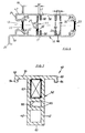
- the abutment strip 40 is designed as a hollow chamber profile and its abutment leg 62 has two walls 42, that are parallel to each other at a distance.
- the walls 42 are inside of the frame with a continuous Web 63 connected, while a cover leg on the rebate side 55 is present, the essential area of the rebate side Occupies frame area and in this way the burglar resistance serves.
- the T-shaped design of the abutment bar 40 means a significant increase in the dimensional stability of the frame spar 39. For this is the abutment bar 40 also specially designed for the rest.
- the cover leg 55 has the abutment leg 62 at its ends 63 parallel frame engaging strips 64, from the rebate space 52 intervene in the material of the frame spar 53 and so ensure that the cover leg 55 is not transverse to this Frame engagement bars 64 can be moved. Together with the abutment leg 32 results in an improved Definition of the entire abutment bar 40.
- the cross-section of the hollow chamber the abutment bar 40 or the abutment leg 62 is considerably stiffened by the fact that within the Abutment leg 62 parallel crossbars 65 present are.
- the transverse webs 65 fulfill their stiffening function addition another function by working in a Distance are arranged, the screwing of fasteners allowed.
- Such fasteners are, for example the fishing pin 41 of fishing 38 to the bracket a door or window frame wing. A fishing pin 41 will then across the two walls 42 between the crosspieces 65 screwed through. The latter have turned towards each other Surfaces of longitudinally running thread holding ribs 66, as well as the spacer bars 59 shown in FIG. 6 and the parallel bars 60 assigned to them.
- the hollow chamber profile of the abutment bar 40 allows it, the reinforcement of a frame or its abutment strips 40 to be coupled together in the frame corner area.
- corner brackets 67 are used, the legs of each end engage in the interior of the abutment strips 40, that are adjacent to each other in the frame corner area and there for example, on a miter or butt joint lie.
- the between the cladding panels 21 and the hollow frame profiles 10 formed space is with the frame 14th provided that trained according to the technical requirements can be.
- the frame fill can, like that for example is indicated in Figure 2, from an inhomogeneous Structure exist. Instead, blocked ones can also be used Wooden strips or honeycomb structures can be used. Also one Insulating glass can be used when the cladding panel 21 leaves a corresponding section, in essentially only in the area of the hollow frame profiles 10 is present.
- both the frame filling 14, as well as the interior of the hollow frame profiles 10 in the desired Can be filled in, for example with heat and / or soundproofing material. It is also possible, to increase bullet resistance by using harder material is used, e.g. Liquid stone.
- the design of the hollow frame profiles results 10 a wide range of options, one Door or a door wing or a window wing too design that he on the one hand the technical requirements, on the other hand the optical requirements and moreover meet the burglar security requirements can.
- Fig.5a to 5d connector 12 used.
- This is essentially a prismatic or cuboid Component with two abutment surfaces 15, the outer contour with the outer contour of the hollow frame profiles 10 is identical. The can be seen in particular by comparing FIG. 5d with FIG. 6.
- the side surfaces 16 with the side walls 17 one Hollow frame profile 10.
- the connector 12 Since the frame hollow profile 10 according to Figure 6 several functional Has profiles, the connector 12 is corresponding customized. On the one hand, this applies to the groove 13, which with the same or similar profile also in the rebate side End faces 54 of the connector 12 is incorporated, that is in those end faces on which frame hollow profiles 10 not concern.
- these grooves 13 of the connector 12 it is possible in these grooves 13 of the connector 12 to arrange drive rod fittings, for example with a corner drive so that the sash can be operated with conventional hardware, for example with a one-hand fitting in training for Casement. Special corner or center locks from Sash frames are therefore with little technical effort possible and can the burglar resistance of the casement further increase.
- FIG. 5d Another functional profiling of the hollow frame profile 10 consists in the mounting strips 19.20.
- Appropriate Fastening strips 19, 20 are also shown in FIG. 5d Connector 12 present, the mounting strips 19.20 of the connector 12 with which the frame hollow profiles 10 are aligned.
- the connector 12 is structured such that it is a Has frame structure, so in the middle has mass-free areas. This is achieved by a lattice structure with lattice webs 30, which each have two opposing frame walls connect with each other and perpendicular to those Lattice webs 30, which are the other opposite one another Connect the frame walls together. According to the 5a, 5c there are a total of four lattice webs 30 which one piece with each other and with the frame of the connector 12 Form structure.
- fastening screws 27 For fastening the connector 12 to the frame profiles 10 serve fastening screws 27, through frame holes 57 into the parallel screw-in strips 29 be screwed in until the screw head is as indicated in Fig. 5c Assumes position and the abutting surface 15 against the joint 11 of the hollow frame section 10 pulls.
- the fastening screw 27 is, for example, a cylinder head screw with internal polygon, the head 28 dimensioned so is that the screw 27 through the recesses 26 can get into the position shown.
- an Allen key is a screw adjustment of the fastening screw 27 also possible if this at the beginning of their Intervention in the screw-in strips 29, for example be arranged in the middle cavity 34 of the connector 12 should.
- a frame hollow profile coupling connector 12 can also can be formed for more than two hollow frame profiles by all four narrow end faces designed as abutting surfaces 15 become.
- Such a connector can, for example, four in Hollow frame profiles arranged cross to one another connect what is important for larger casement structures is. In this case, another fastening technique used.
Landscapes
- Engineering & Computer Science (AREA)
- Civil Engineering (AREA)
- Structural Engineering (AREA)
- Mechanical Engineering (AREA)
- Joining Of Corner Units Of Frames Or Wings (AREA)
- Wing Frames And Configurations (AREA)
- Electrical Discharge Machining, Electrochemical Machining, And Combined Machining (AREA)
Claims (11)
- Armature sur des portes ou des fenêtres, comportant un dormant à disposer de façon fixe et pourvu d'un rebord de butée (40) qui est posé sur une surface de dormant située côté feuillure avec une branche de recouvrement (55) à partir de laquelle une branche de butée (62) pénètre, perpendiculairement et longitudinalement, dans le dormant, une cheville (41) du gond (38) d'un battant étant vissée dans la branche de butée (62), caractérisée en ce que la branche de butée (62) est formée par un profilé creux.
- Armature selon la revendication 1, caractérisée en ce que la branche de butée (62), vue en section transversale, dépasse du milieu de la branche de recouvrement (55), laquelle présente sur ses bords (63) des rebords d'accouplement de châssis (64) parallèles et courts par rapport à la branche de butée (62).
- Armature selon la revendication 1 ou 2, caractérisée en ce que des bandes transversales (65) parallèles sont disposées à l'intérieur de la branche de butée (62) avec un espacement qui permet le vissage de moyens de fixation.
- Armature selon l'une au moins des revendications 1 à 3, caractérisée en ce que les rebords de butée (40) de deux montants de dormant formant un angle sont accouplés à l'aide de cornières.
- Armature selon l'une au moins des revendications 1 à 4, caractérisée en ce que les nervures d'écartement (59) et les nervures (60), parallèles à celles-ci, d'un profilé creux de châssis (10) d'un battant de la porte ou de la fenêtre et/ou les bandes transversales (65) de la branche de butée (62) comportent sur leurs surfaces tournées les unes vers les autres des nervures de fixation filetées longitudinales (66).
- Armature selon l'une au moins des revendications 1 à 5, caractérisée en ce que des vis de fixation de pentures sont vissées entre une nervure d'écartement (59) et la nervure (60) parallèle à celle-ci, et/ou en ce que la cheville de gond (41) est vissée à travers deux parois (42) du profilé creux du rebord de butée (40).
- Armature selon l'une au moins des revendications 1 à 6, caractérisée en ce qu'il est prévu, associé parallèlement à celle-ci, un profilé creux de châssis (10) du battant, lequel profilé présente une rainure (13) ouverte côté feuillure dans laquelle sont fixés des éléments présentant des perçages d'accouplement, ou des éléments de fermeture (18) agissant côté dormant.
- Armature selon l'une au moins des revendications 1 à 7, caractérisée en ce que le profilé creux de châssis (10) comporte au moins une nervure d'écartement (59), qui dépasse de chaque surface intérieure (58) d'une paroi latérale (17), pour un coffre de serrure (45) dont le pêne demi-tour et/ou le pêne dormant pénètrent dans la branche de butée (62).
- Armature selon l'une au moins des revendications 1 à 8, caractérisée en ce que le profilé creux de châssis (10), ses attaches (12) et le rebord de butée (40) sont en métal.
- Armature selon l'une au moins des revendications 1 à 9, caractérisée en ce que le profilé de châssis (10) comporte des rebords de fixation (19, 20) saillant vers l'extérieur, pour des ferrures ou pour des éléments de revêtement, les rebords de fixation (19, 20) d'une paroi latérale (17) dépassant au besoin de la surface de châssis située côté feuillure (24) en formant un recouvrement de châssis.
- Armature selon l'une au moins des revendications 1 à 10, caractérisée en ce que des chevilles de gonds (35) situées côté battant sont vissées dans une butée (37) maintenue par un rebord de fixation (20) et/ou dans une plaque de revêtement (21) maintenue par ce rebord.
Applications Claiming Priority (2)
| Application Number | Priority Date | Filing Date | Title |
|---|---|---|---|
| DE19500226 | 1995-01-05 | ||
| DE19500226A DE19500226C2 (de) | 1995-01-05 | 1995-01-05 | Tür oder Fensterflügel |
Publications (2)
| Publication Number | Publication Date |
|---|---|
| EP0725202A1 EP0725202A1 (fr) | 1996-08-07 |
| EP0725202B1 true EP0725202B1 (fr) | 1999-07-28 |
Family
ID=7751048
Family Applications (2)
| Application Number | Title | Priority Date | Filing Date |
|---|---|---|---|
| EP95120728A Expired - Lifetime EP0725202B1 (fr) | 1995-01-05 | 1995-12-30 | Armature pour portes ou fenêtres |
| EP95120729A Expired - Lifetime EP0725203B1 (fr) | 1995-01-05 | 1995-12-30 | Armature pour portes, fenêtres ou façades |
Family Applications After (1)
| Application Number | Title | Priority Date | Filing Date |
|---|---|---|---|
| EP95120729A Expired - Lifetime EP0725203B1 (fr) | 1995-01-05 | 1995-12-30 | Armature pour portes, fenêtres ou façades |
Country Status (3)
| Country | Link |
|---|---|
| EP (2) | EP0725202B1 (fr) |
| AT (2) | ATE183809T1 (fr) |
| DE (3) | DE19500226C2 (fr) |
Families Citing this family (6)
| Publication number | Priority date | Publication date | Assignee | Title |
|---|---|---|---|---|
| DE19739408C1 (de) * | 1997-09-09 | 1999-06-02 | Pax Gmbh | Verfahren zur Herstellung einer Füllungsplatte, die in einem umgebenden Rahmen aus Profilholmen eingepaßt wird |
| DE19927719A1 (de) * | 1999-06-17 | 2000-12-21 | Peter Willrich | Einrichtung zur Anordnung in einem Spalt zwischen einem Rahmen und einem Flügel |
| DE19962364C2 (de) * | 1999-12-23 | 2003-10-23 | W & S Vario Schicht Systeme Gm | Bauteil |
| DE102005002308B4 (de) * | 2005-01-17 | 2012-06-06 | Adams-Fensterbau Gmbh | Haustür |
| DE102017217360A1 (de) * | 2017-09-29 | 2019-04-04 | Siemens Mobility GmbH | Kundenspezifisches Fahrzeugtürblatt z.B. für ein Schienenfahrzeug |
| PL233482B1 (pl) * | 2017-10-30 | 2019-10-31 | Januszewski Bartosz Zakl Produkcyjny Anbo Spolka Cywilna | Drzwi wewnątrzlokalowe |
Family Cites Families (7)
| Publication number | Priority date | Publication date | Assignee | Title |
|---|---|---|---|---|
| DE8019955U1 (de) * | 1980-10-16 | Kemmlit-Bauelemente Gmbh, 7400 Tuebingen | Element für Wände und/oder Türen | |
| US2862257A (en) * | 1956-10-26 | 1958-12-02 | John A Comer | Hollow core panel |
| EP0074623B1 (fr) * | 1981-09-15 | 1985-12-27 | Wolfgang Zwick | Procédé pour la fabrication de vantaux de portes |
| DE8436580U1 (de) * | 1984-12-14 | 1985-04-11 | Brümmer, Roland, 7108 Möckmühl | Selbstbau - fenster |
| DE3618482A1 (de) * | 1985-06-18 | 1986-12-18 | Knierim GmbH u. Co KG Metall- und Kunststoffverarbeitung, 3500 Kassel | Eckelement fuer insbesondere zur herstellung von sanitaerzellen bestimmte wand- oder tuerelemente |
| DE4308944C3 (de) * | 1993-03-19 | 2002-01-24 | Helmut Siegel | Insektenschutzeinrichtung |
| DE4319945A1 (de) * | 1993-06-16 | 1994-12-22 | Hans Dieter Niemann | Tür- oder Fensterrahmen aus Holz |
-
1995
- 1995-01-05 DE DE19500226A patent/DE19500226C2/de not_active Expired - Fee Related
- 1995-12-30 AT AT95120729T patent/ATE183809T1/de not_active IP Right Cessation
- 1995-12-30 DE DE59506469T patent/DE59506469D1/de not_active Expired - Fee Related
- 1995-12-30 DE DE59506690T patent/DE59506690D1/de not_active Expired - Fee Related
- 1995-12-30 EP EP95120728A patent/EP0725202B1/fr not_active Expired - Lifetime
- 1995-12-30 EP EP95120729A patent/EP0725203B1/fr not_active Expired - Lifetime
- 1995-12-30 AT AT95120728T patent/ATE182652T1/de not_active IP Right Cessation
Also Published As
| Publication number | Publication date |
|---|---|
| DE19500226A1 (de) | 1996-07-18 |
| ATE183809T1 (de) | 1999-09-15 |
| EP0725202A1 (fr) | 1996-08-07 |
| DE59506690D1 (de) | 1999-09-30 |
| EP0725203A1 (fr) | 1996-08-07 |
| ATE182652T1 (de) | 1999-08-15 |
| EP0725203B1 (fr) | 1999-08-25 |
| DE59506469D1 (de) | 1999-09-02 |
| DE19500226C2 (de) | 1997-12-18 |
Similar Documents
| Publication | Publication Date | Title |
|---|---|---|
| EP0275235A2 (fr) | Porte ou fenêtre à battant mobile et verrouillable | |
| EP0725202B1 (fr) | Armature pour portes ou fenêtres | |
| EP0844348B1 (fr) | Penture pour portes ou fenêtres | |
| DE19744832C2 (de) | Anordnung für den Einbau eines Fensterrahmens | |
| EP0792992B1 (fr) | Dormant de porte à montage ultérieur | |
| EP0563550A2 (fr) | Ferrure pour fenêtre ou porte pivotante autour son axe central | |
| AT501873A1 (de) | Profil und verfahren zu dessen herstellung | |
| EP0128372B1 (fr) | Dispositif de fermeture d'un battant d'une porte, fenêtre ou similaire à deux battants | |
| DE8703743U1 (de) | Tür mit einem Sicherheitstürblatt | |
| DE3045813A1 (de) | Fenster oder tuer mit fluegel und rahmen | |
| EP2060726B1 (fr) | Profilé creux | |
| EP1864000B1 (fr) | Vantail de porte ou de fenetre et procede de fabrication associe | |
| EP4202170B1 (fr) | Connecteur, joint bout à bout et procédé de fabrication associé | |
| EP3674568B1 (fr) | Ferrure pour un système de cloisons, en particulier pour cloisons en verre | |
| EP4345240B1 (fr) | Liaison de profilé en métal léger | |
| EP2339095A2 (fr) | Porte, notamment porte en plastique, dotée d'une sécurité de palastre ainsi que sécurité de palastre correspondant | |
| DE102006062161A1 (de) | Kunststoff-Profilsystem für ein Fenster oder eine Tür | |
| DE8426131U1 (de) | Profilrahmen fuer ein fenster, eine tuer od. dgl. mit einem getriebegriff od. dgl. | |
| DE2718651A1 (de) | Bauelement in form eines fensters oder einer tuer | |
| EP4325017A1 (fr) | Profilé isolant pour relier deux éléments profilés pour la réalisation d'un profilé isolé thermiquement et un tel profilé | |
| EP4446552A1 (fr) | Battant mobile par rapport à un dormant d'une fenêtre ou d'une porte et procédé de fixation de deux profilés principaux | |
| AT395462B (de) | Vorgefertigtes, portalartiges rahmenelement, insbesondere tuerzarge | |
| DE29800306U1 (de) | Beschlag für einen Flügelrahmen von Fenstern oder Türen | |
| CH656180A5 (de) | Aus profilen zusammengesetzter beschusshemmender rahmen. | |
| EP2199515B1 (fr) | Profil doté d'une rainure de serrure latérale |
Legal Events
| Date | Code | Title | Description |
|---|---|---|---|
| PUAI | Public reference made under article 153(3) epc to a published international application that has entered the european phase |
Free format text: ORIGINAL CODE: 0009012 |
|
| AK | Designated contracting states |
Kind code of ref document: A1 Designated state(s): AT BE CH DE FR GB LI NL |
|
| 17P | Request for examination filed |
Effective date: 19961205 |
|
| GRAG | Despatch of communication of intention to grant |
Free format text: ORIGINAL CODE: EPIDOS AGRA |
|
| 17Q | First examination report despatched |
Effective date: 19981112 |
|
| GRAG | Despatch of communication of intention to grant |
Free format text: ORIGINAL CODE: EPIDOS AGRA |
|
| GRAH | Despatch of communication of intention to grant a patent |
Free format text: ORIGINAL CODE: EPIDOS IGRA |
|
| GRAH | Despatch of communication of intention to grant a patent |
Free format text: ORIGINAL CODE: EPIDOS IGRA |
|
| GRAA | (expected) grant |
Free format text: ORIGINAL CODE: 0009210 |
|
| AK | Designated contracting states |
Kind code of ref document: B1 Designated state(s): AT BE CH DE FR GB LI NL |
|
| PG25 | Lapsed in a contracting state [announced via postgrant information from national office to epo] |
Ref country code: NL Free format text: LAPSE BECAUSE OF FAILURE TO SUBMIT A TRANSLATION OF THE DESCRIPTION OR TO PAY THE FEE WITHIN THE PRESCRIBED TIME-LIMIT Effective date: 19990728 Ref country code: GB Free format text: LAPSE BECAUSE OF FAILURE TO SUBMIT A TRANSLATION OF THE DESCRIPTION OR TO PAY THE FEE WITHIN THE PRESCRIBED TIME-LIMIT Effective date: 19990728 Ref country code: FR Free format text: LAPSE BECAUSE OF FAILURE TO SUBMIT A TRANSLATION OF THE DESCRIPTION OR TO PAY THE FEE WITHIN THE PRESCRIBED TIME-LIMIT Effective date: 19990728 |
|
| REF | Corresponds to: |
Ref document number: 182652 Country of ref document: AT Date of ref document: 19990815 Kind code of ref document: T |
|
| REG | Reference to a national code |
Ref country code: CH Ref legal event code: EP |
|
| REF | Corresponds to: |
Ref document number: 59506469 Country of ref document: DE Date of ref document: 19990902 |
|
| EN | Fr: translation not filed | ||
| PG25 | Lapsed in a contracting state [announced via postgrant information from national office to epo] |
Ref country code: AT Free format text: LAPSE BECAUSE OF NON-PAYMENT OF DUE FEES Effective date: 19991230 |
|
| PG25 | Lapsed in a contracting state [announced via postgrant information from national office to epo] |
Ref country code: LI Free format text: LAPSE BECAUSE OF NON-PAYMENT OF DUE FEES Effective date: 19991231 Ref country code: CH Free format text: LAPSE BECAUSE OF NON-PAYMENT OF DUE FEES Effective date: 19991231 Ref country code: BE Free format text: LAPSE BECAUSE OF NON-PAYMENT OF DUE FEES Effective date: 19991231 |
|
| NLV1 | Nl: lapsed or annulled due to failure to fulfill the requirements of art. 29p and 29m of the patents act | ||
| GBV | Gb: ep patent (uk) treated as always having been void in accordance with gb section 77(7)/1977 [no translation filed] |
Effective date: 19990728 |
|
| PLBE | No opposition filed within time limit |
Free format text: ORIGINAL CODE: 0009261 |
|
| STAA | Information on the status of an ep patent application or granted ep patent |
Free format text: STATUS: NO OPPOSITION FILED WITHIN TIME LIMIT |
|
| BERE | Be: lapsed |
Owner name: NIEMANN HANS-DIETER Effective date: 19991231 |
|
| 26N | No opposition filed | ||
| PGFP | Annual fee paid to national office [announced via postgrant information from national office to epo] |
Ref country code: DE Payment date: 20001130 Year of fee payment: 6 |
|
| PG25 | Lapsed in a contracting state [announced via postgrant information from national office to epo] |
Ref country code: DE Free format text: LAPSE BECAUSE OF NON-PAYMENT OF DUE FEES Effective date: 20020702 |