EP0725465A1 - Wand- oder Sockelleistenkanal für elektrischen Kabeln oder dergleichen - Google Patents
Wand- oder Sockelleistenkanal für elektrischen Kabeln oder dergleichen Download PDFInfo
- Publication number
- EP0725465A1 EP0725465A1 EP96100521A EP96100521A EP0725465A1 EP 0725465 A1 EP0725465 A1 EP 0725465A1 EP 96100521 A EP96100521 A EP 96100521A EP 96100521 A EP96100521 A EP 96100521A EP 0725465 A1 EP0725465 A1 EP 0725465A1
- Authority
- EP
- European Patent Office
- Prior art keywords
- supporting channel
- wall
- trunking
- lateral
- cover
- Prior art date
- Legal status (The legal status is an assumption and is not a legal conclusion. Google has not performed a legal analysis and makes no representation as to the accuracy of the status listed.)
- Granted
Links
- 210000002105 tongue Anatomy 0.000 claims description 5
- 230000007547 defect Effects 0.000 description 2
- 239000003000 extruded plastic Substances 0.000 description 1
- 238000009434 installation Methods 0.000 description 1
- 238000012423 maintenance Methods 0.000 description 1
- 239000000463 material Substances 0.000 description 1
Images

Classifications
-
- H—ELECTRICITY
- H02—GENERATION; CONVERSION OR DISTRIBUTION OF ELECTRIC POWER
- H02G—INSTALLATION OF ELECTRIC CABLES OR LINES, OR OF COMBINED OPTICAL AND ELECTRIC CABLES OR LINES
- H02G3/00—Installations of electric cables or lines or protective tubing therefor in or on buildings, equivalent structures or vehicles
- H02G3/02—Details
- H02G3/04—Protective tubing or conduits, e.g. cable ladders or cable troughs
- H02G3/0431—Wall trunking
-
- H—ELECTRICITY
- H02—GENERATION; CONVERSION OR DISTRIBUTION OF ELECTRIC POWER
- H02G—INSTALLATION OF ELECTRIC CABLES OR LINES, OR OF COMBINED OPTICAL AND ELECTRIC CABLES OR LINES
- H02G3/00—Installations of electric cables or lines or protective tubing therefor in or on buildings, equivalent structures or vehicles
- H02G3/02—Details
- H02G3/04—Protective tubing or conduits, e.g. cable ladders or cable troughs
- H02G3/0406—Details thereof
- H02G3/0418—Covers or lids; Their fastenings
Definitions
- the present invention relates to cable trunking and in particular to so-called wall- and skirting board-type cable trunking.
- Wall- and skirting board-type cable trunking is known; such trunking is often designed to be used in environments where the functionality of the electrical equipment connected by the trunking has to be combined with a sufficiently attractive appearance, as in the case of offices and private homes.
- Cable trunking as described above often consists of a supporting channel divided into a number of compartments, often differing dimensionally from each other, with a cover which is generally different according to whether the trunking is laid vertically up the wall or in a skirting board position, that is along the wall parallel with and close to the floor; the channel and the cover are generally made of extruded plastic.
- the channel and the cover are connected together by mutually connecting parts on both the lateral margins of the cover and on the lateral walls of the supporting channel.
- These parts may take the form of, for example, ribs fitted into slots.
- Trunking of this type already known in the prior art, has in general a great many drawbacks from the point of view of both installation and subsequent maintenance on the cables laid inside them.
- trunking comprising a supporting channel that may have a plurality of compartments, each with its own compartment cover but all accessible through the same cover common to the entire supporting channel; this feature may cause problems when installing the trunking or when later inspecting or maintaining it.
- the subject of the present invention is therefore wall- and skirting board-type trunking for electrical cables comprising a supporting channel with a back that can be fixed to a wall, and with two lateral walls extending from said back; and a cover consisting of a closing surface and two lateral margins, said lateral walls of the supporting channel and said lateral margins of the cover having means of mutual connection, the trunking being characterized in that said back of the supporting channel is curved so that the cross section of said supporting channel is concave, and in that along its longitudinal axis said supporting channel is provided with a series of seating holes for the wall fixing means.
- both the lateral walls of said supporting channel are provided with two generally C-shaped flexible tongues whose free extremities face their respective lateral wall.
- Another feature of the invention is cable trunking in which the cover consists of a plurality of independent parts divided from each other along the length of the trunking, the supporting channel of said cable trunking being divided into a plurality of compartments, and said dividing walls inside the channel comprising one or more parts that connect with the parts of the cover.
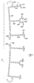
- the numeral 1 denotes the supporting channel of cable trunking according to the present invention.
- This supporting channel 1 is shown in section and close to a wall 4 to which it is to be fixed.
- This supporting channel comprises a back 101 that is concave in cross section from the point of view of the supporting channel 1.
- the back 101 comprises a series of holes 701, the purpose of which will be described below.
- the supporting channel 1 is divided internally by a series of dividing walls 301 that extend, also radially, from the back 101 and divide said supporting channel into a plurality of compartments, five in the case illustrated here.
- a bifurcation 401 with two arms symmetrical about said dividing wall 301.
- a button-tipped projection 441 At the end of one arm of the bifurcation is a button-tipped projection 441 and, extending into the interior of the bifurcation, a tooth-like projection 421, while on the other arm is a similar tooth-like projection 431 and, extending away from the bifurcation, a projection 441.
- said dividing walls 301 comprise a button-tipped projection 311 and a tooth-like projection 321 on the opposite edge from the wall, the purpose of which will be explained below.
- the lateral walls 201 each comprise, joined close to the back 101, a generally C-shaped tongue 501. The free extremity of the tongue 501 is towards the same lateral wall 201.
- the underside of the back has two longitudinal ribs 601 between which the holes 701, whose purpose will be explained below, are located.
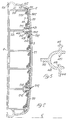
- FIG. 2 illustrates cable trunking according to the invention fixed to a wall 4.
- the supporting channel 1 is the same as that shown in Figure 1 and identical parts are marked with the same numbers.
- the supporting channel 1 is now closed by a cover 2 that has two lateral margins 102 and two closing surfaces 20, each directly connected to a lateral margin 102, and in addition a connecting surface 21 attached to the supporting channel 1 in the manner described later.
- the closing surfaces 20 and 21 are separate from each other.
- the lateral margins 102 of the cover each comprise on the inside face a rib 112 that extends upwards and engages with the projection 211 of the lateral wall 201 of the supporting channel 1.
- Between the lateral margin 102 and the closing surface 20 is a groove 302 by way of a hinge.
- the edge of the closing surface 20 furthest from the lateral margin 102 ends in an intermediate margin 202 on whose free edge is a hook 212.
- the hook 212 engages with the tooth-like projection 421 inside the bifurcation 401 and thus secures the closing surface 20 to the supporting channel 1.
- the two intermediate margins 202 of the closing surface 21 are secured in position by inserting the hooks 212 into the bifurcations 401.
- the compartments in which the supporting channel 1 is divided by the dividing walls 301 are closed by the compartment covers 3, which in this case are of the type illustrated and described by the present applicant in European Patent Application 95105146.5.
- FIG 3 Illustrated in Figure 3 is a second embodiment of the cover according to the invention.
- the cover has just two closing surfaces 22 and 20, each of which is directly connected to a lateral margin 102 and to an intermediate margin 202.
- Figure 5 shows the bifurcation 401 of a dividing wall 301 in detail.
- the supporting channel 1 as illustrated in Fig. 1 and described above, has a concave back 101.
- the curvature of the back 101 minimises that the contact between the wall 4 and said back is excellent whatever the condition of the surface of this wall; moreover, because of this curvature, it is unnecessary to fix said supporting channel 1 elsewhere than through the holes 701 described above.
- the tongues 501 advantageously made of a flexible material, ensure that defects in either the surface of the wall 4 or the surface of the floor 5 are aesthetically concealed.
- the cable trunking of the present invention presents further advantages in other respects: the possibility of dividing the cover 2 into a plurality of closing surfaces of different dimensions can make it easier to access certain particular compartments for certain lengths, as opposed to others, when installing the device, so that removing the cover is not complicated; for, in the case illustrated in Fig. 2, if the engineer needs to inspect one of the two lateral compartments covered by closing surfaces 20, he need simply insert some suitable tool into the slot separating one closing surface 20 from the closing surface 21; the hook 212 of the intermediate margin 202 will thus be disengaged from the tooth-like projection 421 and the portion of the cover of the closing surface 20 will be removable once the projection 211 has been disengaged from the rib 112. It is thus now possible to inspect the compartment.
- wall- and skirting board-type cable trunking according to the present invention can be fixed easily and effectively to any wall whatever its surface may be like, and it is also possible to gain access to the compartments into which the supporting channel of said cable trunking is divided, quickly and without having to remove the whole cover.
Landscapes
- Engineering & Computer Science (AREA)
- Architecture (AREA)
- Civil Engineering (AREA)
- Structural Engineering (AREA)
- Installation Of Indoor Wiring (AREA)
- Details Of Indoor Wiring (AREA)
- Cable Accessories (AREA)
- Apparatus For Radiation Diagnosis (AREA)
- Communication Cables (AREA)
- Insulated Conductors (AREA)
Applications Claiming Priority (2)
| Application Number | Priority Date | Filing Date | Title |
|---|---|---|---|
| IT1995GE000006U IT239272Y1 (it) | 1995-02-02 | 1995-02-02 | Canaletta portacavi o simili a parete e a battiscopa. |
| ITGE950006U | 1995-02-02 |
Publications (2)
| Publication Number | Publication Date |
|---|---|
| EP0725465A1 true EP0725465A1 (de) | 1996-08-07 |
| EP0725465B1 EP0725465B1 (de) | 1999-04-14 |
Family
ID=11354668
Family Applications (1)
| Application Number | Title | Priority Date | Filing Date |
|---|---|---|---|
| EP96100521A Expired - Lifetime EP0725465B1 (de) | 1995-02-02 | 1996-01-16 | Wand- oder Sockelleistenkanal für elektrischen Kabeln oder dergleichen |
Country Status (5)
| Country | Link |
|---|---|
| EP (1) | EP0725465B1 (de) |
| AT (1) | ATE179032T1 (de) |
| DE (1) | DE69602042T2 (de) |
| ES (1) | ES2129895T3 (de) |
| IT (1) | IT239272Y1 (de) |
Cited By (2)
| Publication number | Priority date | Publication date | Assignee | Title |
|---|---|---|---|---|
| EP0920099A1 (de) * | 1997-11-28 | 1999-06-02 | Aparellaje Electrico, S.A. | Kanalbobemteil für elektrische Kabelsysteme |
| AU2010200150B2 (en) * | 2009-01-30 | 2016-08-04 | Assembly Electronics Pty Ltd | A Duct and Method and Arrangement of Mounting a Duct |
Citations (4)
| Publication number | Priority date | Publication date | Assignee | Title |
|---|---|---|---|---|
| DE846713C (de) * | 1950-11-23 | 1952-08-18 | Theodor Klatte Fa | Leiste zum Verlegen von vorzugsweise elektrischen Leitungen u. dgl., insbesondere inVerkehrsmitteln |
| DE1234821B (de) * | 1966-04-16 | 1967-02-23 | Allgemeiner Elektro Bau | Aus einem thermoplatischen Kunststoff oder einem anderen Isoliermaterial bestehendesRohr fuer elektrische Installationen |
| FR2408929A1 (fr) * | 1977-11-09 | 1979-06-08 | Duport Jacques | Profile formant plinthe ou canalisation a fonctions multiples en particulier pour installations electriques |
| FR2473226A1 (fr) * | 1980-01-03 | 1981-07-10 | Villi Canalplast | Gaine porte-cables, notamment pour constructions privees et industrielles prefabriquees |
-
1995
- 1995-02-02 IT IT1995GE000006U patent/IT239272Y1/it active
-
1996
- 1996-01-16 EP EP96100521A patent/EP0725465B1/de not_active Expired - Lifetime
- 1996-01-16 ES ES96100521T patent/ES2129895T3/es not_active Expired - Lifetime
- 1996-01-16 AT AT96100521T patent/ATE179032T1/de not_active IP Right Cessation
- 1996-01-16 DE DE69602042T patent/DE69602042T2/de not_active Expired - Fee Related
Patent Citations (4)
| Publication number | Priority date | Publication date | Assignee | Title |
|---|---|---|---|---|
| DE846713C (de) * | 1950-11-23 | 1952-08-18 | Theodor Klatte Fa | Leiste zum Verlegen von vorzugsweise elektrischen Leitungen u. dgl., insbesondere inVerkehrsmitteln |
| DE1234821B (de) * | 1966-04-16 | 1967-02-23 | Allgemeiner Elektro Bau | Aus einem thermoplatischen Kunststoff oder einem anderen Isoliermaterial bestehendesRohr fuer elektrische Installationen |
| FR2408929A1 (fr) * | 1977-11-09 | 1979-06-08 | Duport Jacques | Profile formant plinthe ou canalisation a fonctions multiples en particulier pour installations electriques |
| FR2473226A1 (fr) * | 1980-01-03 | 1981-07-10 | Villi Canalplast | Gaine porte-cables, notamment pour constructions privees et industrielles prefabriquees |
Cited By (2)
| Publication number | Priority date | Publication date | Assignee | Title |
|---|---|---|---|---|
| EP0920099A1 (de) * | 1997-11-28 | 1999-06-02 | Aparellaje Electrico, S.A. | Kanalbobemteil für elektrische Kabelsysteme |
| AU2010200150B2 (en) * | 2009-01-30 | 2016-08-04 | Assembly Electronics Pty Ltd | A Duct and Method and Arrangement of Mounting a Duct |
Also Published As
| Publication number | Publication date |
|---|---|
| ITGE950006V0 (it) | 1995-02-02 |
| ITGE950006U1 (it) | 1996-08-02 |
| ES2129895T3 (es) | 1999-06-16 |
| EP0725465B1 (de) | 1999-04-14 |
| ATE179032T1 (de) | 1999-04-15 |
| DE69602042D1 (de) | 1999-05-20 |
| DE69602042T2 (de) | 1999-08-19 |
| IT239272Y1 (it) | 2001-02-26 |
Similar Documents
| Publication | Publication Date | Title |
|---|---|---|
| US5792992A (en) | Expandable surface raceway for wiring | |
| US6476327B1 (en) | Split fiber cover and raceway fitting | |
| US7615714B2 (en) | Button style cord connector | |
| EP1306951B1 (de) | Kabelkanalkupplung | |
| US6188024B1 (en) | Elbow for the angular connection of two stretches of raceway for electrical cable system | |
| US6254041B1 (en) | Cable conduit | |
| US5831213A (en) | Electrical outlet box and removable clamp therefor | |
| MXPA00010020A (es) | Broche de retencion para canaleta, particularmente para aparatos electricos. | |
| GB2337868A (en) | Tamper-resistant raceway cover | |
| US5663527A (en) | Stackable conduits with hook and hole clip means | |
| US6537641B1 (en) | Vehicular carpet assembly having a conduit | |
| US6663054B2 (en) | Combined safety clip and closure for a conductor support | |
| US5879185A (en) | Device plate and face plate for wiring device in electric cable raceway | |
| US5898132A (en) | Lay-in wireway | |
| EP0767521A2 (de) | Multifunktionskanal | |
| EP0725465B1 (de) | Wand- oder Sockelleistenkanal für elektrischen Kabeln oder dergleichen | |
| US20010011412A1 (en) | Bracket for lay-on cables | |
| GB2137305A (en) | Duct system | |
| US6455780B2 (en) | Branch connection accessory for fitting at a junction between two lengths of trunking | |
| JPH10108334A (ja) | スライド式ケーブルダクト | |
| EP0465077A1 (de) | Verbindungskiste für eine Kabelkanaleinrichtung | |
| EP0396181B1 (de) | Kanalsystem für elektrische Leitungen und Hilfselemente dafür | |
| GB2296389A (en) | Retaining bar for keeping cables in a duct in place | |
| EP0682394A1 (de) | Wand- oder Sockelleistenkanal für elektrische Kabel | |
| EP1494327A2 (de) | Kanal für elektrische Installationen |
Legal Events
| Date | Code | Title | Description |
|---|---|---|---|
| PUAI | Public reference made under article 153(3) epc to a published international application that has entered the european phase |
Free format text: ORIGINAL CODE: 0009012 |
|
| AK | Designated contracting states |
Kind code of ref document: A1 Designated state(s): AT BE CH DE DK ES FR GB GR IE IT LI LU MC NL PT SE |
|
| AX | Request for extension of the european patent |
Free format text: SI PAYMENT 960116 |
|
| RAX | Requested extension states of the european patent have changed |
Free format text: SI PAYMENT 960116 |
|
| 17P | Request for examination filed |
Effective date: 19960625 |
|
| 17Q | First examination report despatched |
Effective date: 19971216 |
|
| GRAG | Despatch of communication of intention to grant |
Free format text: ORIGINAL CODE: EPIDOS AGRA |
|
| GRAG | Despatch of communication of intention to grant |
Free format text: ORIGINAL CODE: EPIDOS AGRA |
|
| GRAH | Despatch of communication of intention to grant a patent |
Free format text: ORIGINAL CODE: EPIDOS IGRA |
|
| GRAH | Despatch of communication of intention to grant a patent |
Free format text: ORIGINAL CODE: EPIDOS IGRA |
|
| GRAA | (expected) grant |
Free format text: ORIGINAL CODE: 0009210 |
|
| AK | Designated contracting states |
Kind code of ref document: B1 Designated state(s): AT BE CH DE DK ES FR GB GR IE IT LI LU MC NL PT SE |
|
| AX | Request for extension of the european patent |
Free format text: SI PAYMENT 960116 |
|
| PG25 | Lapsed in a contracting state [announced via postgrant information from national office to epo] |
Ref country code: SE Free format text: THE PATENT HAS BEEN ANNULLED BY A DECISION OF A NATIONAL AUTHORITY Effective date: 19990414 Ref country code: NL Free format text: LAPSE BECAUSE OF FAILURE TO SUBMIT A TRANSLATION OF THE DESCRIPTION OR TO PAY THE FEE WITHIN THE PRESCRIBED TIME-LIMIT Effective date: 19990414 Ref country code: LI Free format text: LAPSE BECAUSE OF FAILURE TO SUBMIT A TRANSLATION OF THE DESCRIPTION OR TO PAY THE FEE WITHIN THE PRESCRIBED TIME-LIMIT Effective date: 19990414 Ref country code: IT Free format text: LAPSE BECAUSE OF FAILURE TO SUBMIT A TRANSLATION OF THE DESCRIPTION OR TO PAY THE FEE WITHIN THE PRESCRIBED TIME-LIMIT;WARNING: LAPSES OF ITALIAN PATENTS WITH EFFECTIVE DATE BEFORE 2007 MAY HAVE OCCURRED AT ANY TIME BEFORE 2007. THE CORRECT EFFECTIVE DATE MAY BE DIFFERENT FROM THE ONE RECORDED. Effective date: 19990414 Ref country code: GR Free format text: LAPSE BECAUSE OF NON-PAYMENT OF DUE FEES Effective date: 19990414 Ref country code: CH Free format text: LAPSE BECAUSE OF FAILURE TO SUBMIT A TRANSLATION OF THE DESCRIPTION OR TO PAY THE FEE WITHIN THE PRESCRIBED TIME-LIMIT Effective date: 19990414 Ref country code: BE Free format text: LAPSE BECAUSE OF FAILURE TO SUBMIT A TRANSLATION OF THE DESCRIPTION OR TO PAY THE FEE WITHIN THE PRESCRIBED TIME-LIMIT Effective date: 19990414 Ref country code: AT Free format text: LAPSE BECAUSE OF FAILURE TO SUBMIT A TRANSLATION OF THE DESCRIPTION OR TO PAY THE FEE WITHIN THE PRESCRIBED TIME-LIMIT Effective date: 19990414 |
|
| REF | Corresponds to: |
Ref document number: 179032 Country of ref document: AT Date of ref document: 19990415 Kind code of ref document: T |
|
| REG | Reference to a national code |
Ref country code: CH Ref legal event code: EP |
|
| REG | Reference to a national code |
Ref country code: IE Ref legal event code: FG4D |
|
| REF | Corresponds to: |
Ref document number: 69602042 Country of ref document: DE Date of ref document: 19990520 |
|
| ET | Fr: translation filed | ||
| REG | Reference to a national code |
Ref country code: ES Ref legal event code: FG2A Ref document number: 2129895 Country of ref document: ES Kind code of ref document: T3 |
|
| PG25 | Lapsed in a contracting state [announced via postgrant information from national office to epo] |
Ref country code: PT Free format text: LAPSE BECAUSE OF FAILURE TO SUBMIT A TRANSLATION OF THE DESCRIPTION OR TO PAY THE FEE WITHIN THE PRESCRIBED TIME-LIMIT Effective date: 19990714 Ref country code: DK Free format text: LAPSE BECAUSE OF FAILURE TO SUBMIT A TRANSLATION OF THE DESCRIPTION OR TO PAY THE FEE WITHIN THE PRESCRIBED TIME-LIMIT Effective date: 19990714 |
|
| NLV1 | Nl: lapsed or annulled due to failure to fulfill the requirements of art. 29p and 29m of the patents act | ||
| REG | Reference to a national code |
Ref country code: CH Ref legal event code: PL |
|
| PG25 | Lapsed in a contracting state [announced via postgrant information from national office to epo] |
Ref country code: LU Free format text: LAPSE BECAUSE OF NON-PAYMENT OF DUE FEES Effective date: 20000116 Ref country code: IE Free format text: LAPSE BECAUSE OF NON-PAYMENT OF DUE FEES Effective date: 20000116 Ref country code: GB Free format text: LAPSE BECAUSE OF NON-PAYMENT OF DUE FEES Effective date: 20000116 |
|
| PG25 | Lapsed in a contracting state [announced via postgrant information from national office to epo] |
Ref country code: MC Free format text: THE PATENT HAS BEEN ANNULLED BY A DECISION OF A NATIONAL AUTHORITY Effective date: 20000131 |
|
| PLBE | No opposition filed within time limit |
Free format text: ORIGINAL CODE: 0009261 |
|
| STAA | Information on the status of an ep patent application or granted ep patent |
Free format text: STATUS: NO OPPOSITION FILED WITHIN TIME LIMIT |
|
| 26N | No opposition filed | ||
| GBPC | Gb: european patent ceased through non-payment of renewal fee |
Effective date: 20000116 |
|
| REG | Reference to a national code |
Ref country code: IE Ref legal event code: MM4A |
|
| PGFP | Annual fee paid to national office [announced via postgrant information from national office to epo] |
Ref country code: DE Payment date: 20060102 Year of fee payment: 11 |
|
| PGFP | Annual fee paid to national office [announced via postgrant information from national office to epo] |
Ref country code: ES Payment date: 20070412 Year of fee payment: 12 |
|
| PG25 | Lapsed in a contracting state [announced via postgrant information from national office to epo] |
Ref country code: DE Free format text: LAPSE BECAUSE OF NON-PAYMENT OF DUE FEES Effective date: 20070801 |
|
| REG | Reference to a national code |
Ref country code: FR Ref legal event code: ST Effective date: 20070930 |
|
| REG | Reference to a national code |
Ref country code: FR Ref legal event code: D3 |
|
| REG | Reference to a national code |
Ref country code: ES Ref legal event code: FD2A Effective date: 20080117 |
|
| PG25 | Lapsed in a contracting state [announced via postgrant information from national office to epo] |
Ref country code: ES Free format text: LAPSE BECAUSE OF NON-PAYMENT OF DUE FEES Effective date: 20080117 |
|
| REG | Reference to a national code |
Ref country code: FR Ref legal event code: PLFP Year of fee payment: 20 |
|
| PGFP | Annual fee paid to national office [announced via postgrant information from national office to epo] |
Ref country code: FR Payment date: 20150202 Year of fee payment: 20 |
|
| REG | Reference to a national code |
Ref country code: FR Ref legal event code: CA Effective date: 20160217 |