EP0725532B1 - Bildverarbeitungsgerät mit einer Funktion zur Bildbereichsfestlegung - Google Patents
Bildverarbeitungsgerät mit einer Funktion zur Bildbereichsfestlegung Download PDFInfo
- Publication number
- EP0725532B1 EP0725532B1 EP96101296A EP96101296A EP0725532B1 EP 0725532 B1 EP0725532 B1 EP 0725532B1 EP 96101296 A EP96101296 A EP 96101296A EP 96101296 A EP96101296 A EP 96101296A EP 0725532 B1 EP0725532 B1 EP 0725532B1
- Authority
- EP
- European Patent Office
- Prior art keywords
- density
- image
- value
- data
- target pixel
- Prior art date
- Legal status (The legal status is an assumption and is not a legal conclusion. Google has not performed a legal analysis and makes no representation as to the accuracy of the status listed.)
- Expired - Lifetime
Links
- 238000012545 processing Methods 0.000 title claims description 35
- 239000011159 matrix material Substances 0.000 claims description 27
- 230000003287 optical effect Effects 0.000 claims description 4
- 238000003672 processing method Methods 0.000 claims 2
- 239000003550 marker Substances 0.000 description 75
- 238000000605 extraction Methods 0.000 description 59
- 238000001514 detection method Methods 0.000 description 31
- 238000004364 calculation method Methods 0.000 description 16
- 230000007246 mechanism Effects 0.000 description 9
- 239000000284 extract Substances 0.000 description 7
- 238000012546 transfer Methods 0.000 description 7
- 238000012937 correction Methods 0.000 description 4
- 239000004065 semiconductor Substances 0.000 description 4
- 230000003111 delayed effect Effects 0.000 description 3
- 238000010586 diagram Methods 0.000 description 3
- 230000001965 increasing effect Effects 0.000 description 3
- 230000004044 response Effects 0.000 description 3
- 238000000926 separation method Methods 0.000 description 3
- DNHDRUMZDHWHKG-UHFFFAOYSA-N wieland–miescher ketone Chemical compound C1CC(=O)C=C2CCCC(=O)C21C DNHDRUMZDHWHKG-UHFFFAOYSA-N 0.000 description 3
- 238000003705 background correction Methods 0.000 description 2
- 230000015572 biosynthetic process Effects 0.000 description 2
- 230000001934 delay Effects 0.000 description 2
- 238000002474 experimental method Methods 0.000 description 2
- 238000000034 method Methods 0.000 description 2
- 238000005452 bending Methods 0.000 description 1
- 230000005540 biological transmission Effects 0.000 description 1
- 238000006243 chemical reaction Methods 0.000 description 1
- 239000003795 chemical substances by application Substances 0.000 description 1
- 238000007796 conventional method Methods 0.000 description 1
- 230000003247 decreasing effect Effects 0.000 description 1
- 230000000593 degrading effect Effects 0.000 description 1
- 230000001419 dependent effect Effects 0.000 description 1
- 230000002708 enhancing effect Effects 0.000 description 1
- 238000005286 illumination Methods 0.000 description 1
- 230000005855 radiation Effects 0.000 description 1
- 238000005070 sampling Methods 0.000 description 1
Images


Classifications
-
- H—ELECTRICITY
- H04—ELECTRIC COMMUNICATION TECHNIQUE
- H04N—PICTORIAL COMMUNICATION, e.g. TELEVISION
- H04N1/00—Scanning, transmission or reproduction of documents or the like, e.g. facsimile transmission; Details thereof
- H04N1/38—Circuits or arrangements for blanking or otherwise eliminating unwanted parts of pictures
Definitions
- the present invention relates to an image processing apparatus capable of processing an image and, more particularly, to a digital copying machine for identifying a region designated with a marker pen.
- a method is known well with which a black-and-white binary image is marked with a pen having an intermediate density, e.g., a marker pen (a pen having an intermediate density will be referred to as a marker pen hereinafter), thereby designating a region.
- a marker pen a pen having an intermediate density will be referred to as a marker pen hereinafter
- a black-and-white binary image is marked with a marker pen, and only a portion marked with the marker pen (to be referred to as a marker portion hereinafter) is extracted from the image.
- the density of the background portion of the original is low, the density of the marker portion is higher than that of the background, and the density of the character/figure portion of the original is higher than that of the marker portion.
- the marker portion is extracted by using this density difference.
- a density portion including the density distribution range of the marker portion and sandwiched by two types of binary thresholds is extracted. Thereafter, a noise component, e.g., a character outline, included in the extracted image is removed, thereby extracting a specific marker portion.
- a noise component e.g., a character outline
- a portion marked with a marker pen must be extracted from the original.
- a marker portion from image density information by using a single CCD, based on the fact that the marker portion has an intermediate density between the white (background portion) density and the black (character portion) density of the original, two types of binary thresholds th1 and th2 for extracting an intermediate density are prepared, and data existing between the two thresholds th1 and th2 is extracted as an intermediate-density frame (marker portion), as shown in FIG. 4.
- the character edge portion of a high-density portion is extracted as an intermediate-density portion due to the influence of the sampling cycle of the CCD and the blur of the edge portion.
- a noise component e.g., the character edge portion (character outline portion)
- an intermediate-density image e.g., a character outline portion, other than the marker portion existing on the original is erroneously extracted as a noise component, thus degrading the extracted image.
- the influence of the noise component is large in extraction from an image enlarged by an input optical system as well. Accordingly, the extracting precision of a marker portion in a black-and-white binary image is poor, and the extracting precision of a marker portion in an image enlarged by the input system is poor.
- EP-A- 0 632 642 discloses an extraction device for extracting a marked region within an original document by discriminating the region of the marker having an intermediate density level.
- First an extraction threshold level calculation section calculates the lower limit value and the upper limit value of the marker pen extract density.
- the density extract section only outputs, from the picture data, the pixels having the density between the lower and upper levels as marker pen pixels. Pixels in the edge region of an original image (a character or drawing) are often mistaken as intermediate density pixel within a marked area when the number of such pixels becomes greater than half of the number of the pixels detected by a CCD.
- EP-A-0 632 642 describes a device for discriminating edges even on a faint image.
- a gray level gradient is retrieved from the gray values of the image for classifying the pixels into 4 values. Then a sequence of pixels in the main scanning direction are determined as edge portion pixels dependent on predetermined gray level patterns thereby enhancing the contrast of the image.
- An object of the invention is to provide an image processing apparatus capable of removing the intermediate-density portion of a character edge portion present in the extracted image of a black-and-white binary image, so that the extracting precision of a marker portion in a black-and-white binary image is improved.
- an image processing apparatus comprising: means for reading an original image as multi-value image data in units of a pixel; means for converting the multi-value image data supplied from the reading means into data corresponding to a high density and an intermediate density; means for preparing a predetermined number of adjacent pixels of data supplied from the converting means, the pixels of one unit including a target pixel; and means for determining that the target pixel is intermediate-density portion data of the original image, when the target pixel has the intermediate-density and the pixels being adjacent to the target pixel do not have the high-density.
- an image processing apparatus comprising: means for scanning an original in a main scanning direction and a subscanning direction perpendicular to the main scanning direction, thereby providing image data corresponding to each pixel in an original image; threshold calculating means for calculating first and second thresholds from the density distribution to change the image data into three-value data on the basis of an image density distribution from the image data provided by the scanning means; three-value processing means for converting multi-value data into three values indicating a high density, an intermediate density, and a low density by using the first and second thresholds; first delaying means for delaying an output from the three-value processing means one line in the subscanning direction; second delaying means for delaying the output from the three-value processing means two lines in the subscanning direction; means for preparing one unit by using a predetermined number of adjacent pixels of data supplied from the converting means, the pixels of one unit including a target pixel; means for determining that the target pixel is intermediate-density portion data of
- Image data is converted into three-value data corresponding to a high-density portion, an intermediate-density portion, and a low-density portion by the converting means.
- the three-value data is delayed one line by the first delaying means in the subscanning direction, and is delayed two lines by the second delaying means in the subscanning direction.
- a target pixel is compared with a pixel adjacent to it by using the output from the three-value processing means and outputs from the first and second delaying means.
- a portion in which the target pixel is an intermediate-density portion and the pixel adjacent to the target pixel is not a high-density portion is extracted as intermediate-density portion data, and a region indicated by the extracted intermediate-density portion data is identified.
- a target pixel is compared with a pixel adjacent to the target pixel.
- a portion in which the target pixel is an intermediate-density portion and the pixel adjacent to the target pixel is not a high-density portion is extracted as intermediate-density portion data.
- a region indicated by the extracted intermediate-density portion data is identified.
- the intermediate-density portion of a character edge portion present in an image extracted from a black-and-white image is removed, and only a marker portion is extracted.
- the extracting precision of the marker in a black-and-white binary image is improved, and the extracting precision of the marker in an image enlarged by an input system is improved greatly.
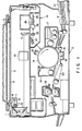
- FIG. 1 is a sectional view showing the internal structure of a digital copying machine as an image processing apparatus.
- the digital copying machine has a scanner portion 1 for optically reading image information on an original O and a printer engine 2 for outputting an image read through the scanner portion 1 onto a recording medium, i.e., copy paper P.
- a recording medium i.e., copy paper P.
- the original to be copied is placed on an original table 3.
- the original O placed on the original table 3 is illuminated with a fluorescent or exposure lamp 4 serving as a light source that moves in the subscanning direction.
- the light beam reflected by the original O illuminated with the exposure lamp 4 is photoelectrically converted by a CCD sensor 5 serving as a photoelectric converting element, so that the image information of the reflected light beam is converted into an image signal.
- a reflector 6 for efficiently converging the illumination light emerging from the exposure lamp 4 onto the original O is arranged beside the exposure lamp 4.
- a plurality of mirrors 7, 8, and 9 for bending the optical path of the light beam directed from the original O toward the CCD sensor 5, i.e., the light beam reflected by the original O, a lens 10 for converging the reflected light onto the condensing surface of the CCD sensor 5, and the like are arranged between the exposure lamp 4 and the CCD sensor 5.
- An optical system for guiding the light beam emitted from the exposure lamp 4 and reflected by the original O is placed on carriages 11 and 12 and conveyed in the subscanning direction by a pulse motor (not shown).
- a region of the original O in the main scanning direction is illuminated with the exposure lamp 4 and the carriages 11 and 12 are moved in the subscanning direction, the regions of the original O in the main scanning direction are sequentially illuminated, so that the entire region of the original O is illuminated with the exposure lamp 4.
- An original cover 13 for bringing the original O into tight contact with the original table 3 is arranged above the original table 3.
- an SDF i.e., a semi-auto document feeder
- an ADF i.e., an automatic document feeder
- a cylindrical photosensitive drum 14 is provided at the image forming portion serving as the printer engine 2.
- the photosensitive drum 14 is rotated in a desired direction through a motor (not shown) or the like, and is charged to a desired potential.
- a laser beam irradiates the photosensitive drum 14
- the potential of a region irradiated with the laser beam is changed, and an electrostatic latent image is formed on the photosensitive drum 14.
- a charge unit 15, a laser unit 16, a developing unit 17, a transfer unit 18, and a separation unit 19 are arranged around the photosensitive drum 14.
- the charge unit 15 gives a desired potential to the photosensitive drum 14.
- the laser unit 16 outputs to the photosensitive drum 14 a laser beam modulated in accordance with the image information.
- the developing unit 17 supplies a visualizing agent, i.e., a toner, to the electrostatic latent image formed on the photosensitive drum 14 by the laser beam output from the laser unit 16, thereby developing the electrostatic latent image.
- the transfer unit 18 transfers a visible toner image on the photosensitive drum 14 which is developed by the developing unit 17 onto a recording medium, i.e., the copy paper P, fed from a recording medium feed portion (to be described later).
- the separation unit 19 separates the copy paper P from the photosensitive drum 14.
- the laser unit 16 is constituted by a semiconductor laser oscillator 24, a polygon mirror 25, an f- ⁇ lens 26, a mirror 27, and a mirror motor 28.
- the semiconductor laser oscillator 24 generates a laser beam.
- the polygon mirror 25 changes the laser beam supplied from the semiconductor laser oscillator 24 through a collimator lens (not shown) into beams in units of lines.
- the f- ⁇ lens 26 changes the laser beams in units of scanning lines supplied from the polygon mirror 25 into parallel light.
- the mirror 27 reflects the parallel light emerging from the f- ⁇ lens 26 and guides it to the photosensitive drum 14.
- the mirror motor 28 rotates the polygon mirror 25.
- a cleaner unit 20 is arranged on the downstream side of the separation unit 19 in the rotational direction of the photosensitive drum 14.
- the cleaner unit 20 removes the toner remaining on the surface of the photosensitive drum 14 and erases a change in potential, which is caused on the photosensitive drum 14 by the laser beam, for subsequent image formation.
- a recording medium feed portion 21 for feeding copy paper P, on which the toner image formed on the photosensitive drum 14 is to be transferred, toward the transfer unit 18 is arranged between the developing unit 17 and the transfer unit 18.
- a fixing unit 22 for fixing the toner image on the copy paper P is provided at a position toward which the copy paper P, on which the toner image is transferred by the transfer unit 18, is separated from the photosensitive drum 14.
- a convey unit 23 for conveying the copy paper P toward the fixing unit 22 is arranged between the fixing unit 22 and the transfer unit 18.
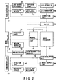
- reference numeral 31 denotes a main controller for controlling the overall digital copying machine.
- Three subcontrollers 32 to 34 for controlling the respective portions are connected to the main controller 31.
- the main controller 31 is also connected to an operation panel 35, a region managing portion 36, and an image processor 37, to control them.
- the operation panel 35 designates various types of image processing operations.
- the region managing portion 36 manages an image processing region.
- the image processor 37 consists of an image quality improving unit for improving the image quality of the input image, an image editing unit for editing the image, and an image processing unit for processing the image.
- the main controller 31 is also connected to a buffer 38 for temporarily storing image information, and a marker extracting unit (marker detection unit) 39 for detecting a marker portion.
- the subcontroller 32 is connected to a light source controller 40, a mechanism driver 42, an A/D converter 43, and a correction unit 44, to control them.
- the light source controller 40 controls the light source light intensity of the exposure lamp 4.
- the mechanism driver 42 controls a mechanical input unit mechanism 41, e.g., a paper feed mechanism, shown in FIG. 1.
- the A/D converter 43 converts an analog image signal, obtained by conversion through the CCD sensor 5 that detects a reflected light beam and converts it into an image signal, into a digital signal.
- the correction unit 44 corrects the image signal by, e.g., shading.
- the light source controller 40 is connected to the exposure lamp 4 serving as the light source, to control the light intensity of the exposure lamp 4.
- the mechanism driver 42 is connected to the input unit mechanism 41, e.g., a carriage-moving pulse motor, to drive the pulse motor. Accordingly, the entire region of the original O is illuminated with appropriate radiation light.
- the subcontroller 33 is connected to an image developing unit 45, an image output unit 46, a detection unit 47, and a mechanism driver 49, to control them.
- the image developing unit 45 develops an edited or processed image signal for the purpose of image formation, and stores the developed image signal.
- the image output unit 46 receives an image from the image developing unit 45 and outputs it as a laser modulation signal.
- the detection unit 47 detects a laser beam output from the semiconductor laser oscillator 24 of the laser unit 16 and adjusts the light intensity of the laser beam.
- the mechanism driver 49 drives an output unit mechanisms 48 of, e.g., the driving system such as a motor and a solenoid in the laser unit 16.
- the subcontroller 34 is connected to a data transmitter/receiver 50 to control data transmission/ reception to/from external equipment.
- the original O is illuminated with the exposure lamp 4.
- the light beam reflected by the original O is focused on the CCD sensor 5 and is converted into an analog electrical signal.
- This analog image signal is converted into a digital signal by the A/D converter 43 and supplied to the correction unit 44 for the purpose of shading correction.
- the image signal subjected to shading correction by the correction unit 44 is temporarily stored in the buffer 38, and is output to the image processor 37 and the marker extracting unit 39.
- the image quality of the image signal output from the buffer 38 is improved by the image improving unit (not shown).
- the improved image signal is edited by the image editing unit (not shown) by using marker extraction data supplied from the marker extracting unit 39.
- the edited image signal is processed by the image processing unit (not shown) and output to the image developing unit 45.
- the marker extracting unit 39 extracts a marker portion from the image signal supplied from the buffer 38. More specifically, the marker extracting unit 39 removes the intermediate-density portion of the character edge portion present in the extracted image and extracts only the marker portion, and is constituted by a switch 51, an original density detection unit 52, an extraction threshold calculation unit 53, a three-value processor 54, line delay units 55 and 56, a thinning unit 57, a frame extracting unit 58, and a post-processor 59, as shown in FIG. 3.
- the switch 51 is switched in response to a switching signal supplied from the main controller 31, and outputs the image signal supplied from the buffer 38 to the original density detection unit 52 during pre-scanning and to the three-value processor 54 during copying.
- the original density detection unit 52 detects the density data of the original from the image signal supplied from the buffer 38 through the switch 51. The detection result is output to the extraction threshold calculation unit 53.
- the extraction threshold calculation unit 53 calculates two types of thresholds, used for performing three-value processing, based on data supplied from the original density detection unit 52.
- the calculated thresholds are output to the three-value processor 54.
- the three-value processor 54 changes the image signal supplied from the buffer 38 through the switch 51 into three-value data by using the two types of thresholds supplied from the extraction threshold calculation unit 53.
- the three-value data is output to the frame extracting unit 58 and the line delay unit 55.
- the line delay unit 55 delays the three-value data supplied from the three-value processor 54 one scanning line.
- the line-delayed data is output to the line delay unit 56 and the frame extracting unit 58.
- the line delay unit 56 delays data supplied from the line delay unit 55 one scanning line. More specifically, the three-value data supplied from the three-value processor 54 is delayed two lines in the subscanning direction, and this line-delayed data is output to the frame extracting unit 58.
- the thinning unit 57 thins data in the write operations of the line delay units 55 and 56 in response to a control signal supplied from the main controller 31, thereby thinning the input data during frame extraction.
- the thinning unit 57 outputs thinned data, write reset WRST, and read reset RRST in response to the control signal.
- the write reset RWST and the read reset RRST are output to the line delay units 55 and 56, and the thinned data is output to the frame extracting unit 58.
- the frame extracting unit 58 extracts an intermediate-density frame present in the image data in accordance with an extraction algorithm by using the three-value data which is supplied from the three-value processor 54, the three-value data which is supplied from the line delay unit 55 and which has been changed to three-value data preceding to the current data by one line, and the three-value data which is supplied from the line delay unit 56 and which has been changed to three-value data preceding to the current data by two lines.
- the frame extraction data is output to the post-processor 59.
- the post-processor 59 removes a noise component included in the extracted marker signal and performs expansion processing for restoring the image from which the noise component has been removed to the original size.
- the marker extracting unit 39 will be described in detail.
- the background density of the original O and the character density of the original O are read in advance by the CCD sensor 5 (in accordance with pre-scanning or the like), and the background density data and the character density data used for marker portion extraction are determined.
- the background density and the character density of the original O are detected by the original density detection unit 52.
- the original image data read by the CCD sensor 5 is output to the original density detection unit 52 through the switch 51.
- the density distribution of a black-and-white image has three peaks, as shown in FIG. 4 showing the concept of the frequency with respect to the density of the original O.
- the background density of the original O is distributed at comparatively low densities in the entire detection density range.
- the density of a character/figure is distributed at comparatively high densities.
- the intermediate-density range between the background density and the character/figure density is the density range of the marker portion.
- the original density detection unit 52 determines the density distribution from the image density read from the buffer 38, calculates the background density and the character density, and outputs the calculated densities to the following extraction threshold calculation unit 53.
- the extraction threshold calculation unit 53 calculates the extraction binary thresholds th1 and th2 used for the purpose of marker portion extraction based on the background density and the character density supplied from the original density detection unit 52.
- the density of the read marker portion is approximately expressed by a following equation: (density of read marker portion) ⁇ (background density of original O) + (density of pure marker portion)
- the extraction density range of the marker portion of the actual original O can be calculated.
- FIGS. 5 and 6 show the concepts of calculation of the extraction thresholds.
- th2 (character portion density) - width3
- Width1 to width3 are fixed values obtained by experiments and represent
- th2 (character portion density) - width6
- th1 (background density) + width7.
- Width4 to width7 are fixed values obtained by experiments and represent
- a value measured in advance is set as a parameter.
- the thresholds th1 and th2 that are calculated by the extraction threshold calculation unit 53 in this manner are output to the three-value processor 54.
- the three-value processor 54 performs three-value processing of the original read data supplied from the switch 51 by using the thresholds th1 an th2 supplied from the extraction threshold calculation unit 53.
- the background portion is defined as 0
- the density range of the marker portion is defined as 1
- the high-density portion is defined as 2.
- the data is changed to three-value data in accordance with this definition.
- the relationship between the thresholds th1 and th2 of three-value processing and input image data is as follows:
- the image data is changed to three-value data in accordance with the above processing operations.
- an intermediate-density portion exists on the intermediate-density frame portion as well as on the edge portion of the high-density portion (character portion).
- a logic circuit is provided and frame extraction is performed. With this logic circuit, detection is performed as to whether or not a high-density portion is present in a detection matrix (to be described later). If a high-density portion exists in the detection matrix, even if its target pixel has an intermediate density, this portion is not extracted as an intermediate-density frame.
- the three-value data is output to the frame extracting unit 58 and the line delay unit 55.
- the line delay unit 55 is constituted by a FIFO and the like, and outputs data, obtained by delaying one line the three-value data supplied from the three-value processor 54, to the line delay unit 56 and the frame extracting unit 58.
- the line delay unit 56 is also constituted by a FIFO and the like, and outputs data, obtained by delaying two lines the three-value data supplied from the three-value processor 54, to the frame extracting unit 58.
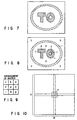
- the frame extracting unit 58 defines an (m ⁇ n) extraction matrix and extracts an intermediate-density frame by using a feature amount in this matrix. More specifically, the frame extracting unit 58 extracts an intermediate-density frame based on pixel data present in the matrix.
- a frame extraction matrix is defined for image data which has been subjected to three-value processing.
- the detection matrix is formed by delaying, in the subscanning direction, a pixel which has been subjected to three-value processing by using an external memory, e.g., an SRAM or a FIFO, and an FF circuit serving as a register.
- the frame extracting unit 58 is constituted by, e.g., two-stage FF (flip-flop) circuits 61 and 62, two-stage FF circuits 63 and 64, two-stage FF circuits 65 and 66, and a frame extracting circuit 67, as shown in FIG. 11.
- the FF circuits 61 and 62 shift an output (3ST0X) supplied from the three-value processor 54.
- the FF circuits 63 and 64 shift an output (3ST1X) supplied from the line delay unit 55.
- the FF circuits 65 and 66 shift an output (3ST2X) supplied from the line delay unit 56.
- the frame extracting circuit 67 is supplied with data (each having 2 bits) of the respective bits a to i constituting the above detection matrix (see FIG. 9).
- a set output from the FF circuit 62 is supplied to the frame extracting circuit 67 as data a .
- a set output from the FF circuit 61 is supplied to the frame extracting circuit 67 as data b .
- An output (3ST0X) from the three-value processor 54 is supplied to the frame extracting circuit 67 as data c .
- a set output from the FF circuit 64 is supplied to the frame extracting circuit 67 as data d .
- a set output from the FF circuit 63 is supplied to the frame extracting circuit 67 as data e .
- An output (3ST1X) from the line delay unit 55 is supplied to the frame extracting circuit 67 as data f .
- An output from the line delay unit 55 is supplied to the frame extracting circuit 67 as data g .
- a set output from the FF circuit 65 is supplied to the frame extracting circuit 67 as data h .
- An output (3ST1X) from the line delay unit 56 is supplied to the frame extracting circuit 67 as data i .
- the frame extracting circuit 67 is also supplied with 0 to 3 as thinned data (MOD1X) from the thinning unit 57.
- the thinned data corresponds to the copying magnification. For example, when the magnification is 500% or more, 2 is output.
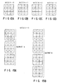
- FIGS. 13 and 14 A processing example of the frame extracting unit 58 in the above arrangement will be described with reference to FIGS. 13 and 14. Assume that 0 is supplied from the thinning unit 57 as the thinned data (MOD1X). For example, when the three-value output has pixel data as shown in FIG. 13, extraction is performed by using a 3 ⁇ 3 detection matrix, so that frame extraction data as shown in FIG. 14 is output.
- the frame extracting circuit 67 outputs 1 as the frame extraction data M3S.
- the frame extracting circuit 67 outputs 0 as the frame extraction data M3S.
- an intermediate-density component present on the edge of (or around) a high-density portion (character portion) can be removed by detecting an intermediate-density portion adjacent to a high-density portion by using a detection matrix.
- a signal is subjected to noise component removal and expansion processing by the post-processor 59, is extracted as marker portion extraction data of an intermediate-density frame, and is output to the image processor 37.
- the image processor 37 includes erasure of the marker portion data extracted from the image data.
- an intermediate-density portion and a high-density portion may be detected by using two types of binary processors 54a and 54b, in place of the three-value processor 54 in FIG. 3, and an intermediate-density frame may be detected from the detection results of the high-density portion and the intermediate-density portion.
- the frame extracting precision of an image enlarged by the input system in the subscanning direction can be improved. This will be described below.
- FIGS. 17A and 17B show the concept of the density distribution in the subscanning direction of a one-to-one (100%) image
- FIGS. 17C and 17D show the concept of the density distribution of an image which is enlarged two times (200%) in the subscanning direction.
- the range extracted as an intermediate-density portion is larger in the 200% image than in the 100% image.
- a thinning circuit for the subscanning direction is provided, so that a processing circuit capable of performing accurate frame extraction even from an enlarged image without increasing the memory size can be obtained.
- write reset WRST and read reset RRST as shown in FIG. 20B are supplied from the thinning unit 57 to the line delay units 55 and 56 at an output timing of each scanning line of the three-value processor 54 as shown in FIG. 20A.
- the three-value processor 54 outputs image data in units of scanning lines, as shown in FIG. 20C
- the line delay unit 55 outputs data obtained by delaying the data output from the three-value processor 54 one line in the subscanning direction, as shown in FIG. 20D
- the line delay unit 56 outputs data obtained by delaying the data output from the three-value processor 54 two lines in the subscanning direction, as shown in FIG. 20E.
- the thinning unit 57 supplies write reset WRST for every other line as shown in FIG. 21B and read reset RRST in units of lines as shown in FIG. 21C to the line delay units 55 and 56 in synchronism with the output timing in units of lines of the three-value processor 54 shown in FIG. 21A.
- the line delay unit 55 generates outputs from the three-value processor 54 on every other line twice for two lines, as shown in FIG. 21D.
- the line delay unit 56 generates the output from the line delay unit 55 with a delay of two lines in the subscanning direction, as shown in FIG. 21E.
- the data input to the frame extracting unit 58 can be converted into an apparent 100%-equivalent image signal.
- data to be input to the frame extracting unit 58 is thinned in the subscanning direction to have discrete values (a 100%-equivalent signal).
- a 100%-equivalent signal is input to the frame extracting unit 58 during frame extraction, and during output, continuous frame extraction data matching the magnification of the image is output. More specifically, the 200%-equivalent image shown in FIG. 18 is converted into an apparent 100%-equivalent image as shown in FIG. 13. Frame extraction is preformed by using this converted image, and frame extraction data as shown in FIG. 14 is obtained. When this data is enlarged, frame extraction data as shown in FIG. 23 can be obtained.
- an image processing apparatus in which, in extraction of a marker portion of a black-and-white image, an intermediate-density portion present on a character edge portion can be removed, thus improving the marker portion extracting precision, and in which the marker portion extracting precision will not be decreased even when extraction is performed from an enlarged image.
Landscapes
- Engineering & Computer Science (AREA)
- Multimedia (AREA)
- Signal Processing (AREA)
- Editing Of Facsimile Originals (AREA)
- Facsimile Image Signal Circuits (AREA)
- Control Or Security For Electrophotography (AREA)
Claims (17)
- Bildverarbeitungsgerät mit:Mitteln (1) zum Lesen eines Originalbildes als Mehrwert-Bilddaten in Einheiten eines Pixels; undMitteln (54) zur Wandlung der Mehrwert-Bilddaten, die von den Lesemitteln (1) geliefert werden, in Daten, die mit einer hohen Dichte, einer Zwischendichte und einer geringen Dichte korrespondieren; gekennzeichnet durchMittel (58) zur Präparierung einer Einheit von Pixeln (a - i) von einer vorbestimmten Anzahl von Pixeln von Daten, die von den Wandlungsmitteln (54) geliefert werden, wobei die Pixel einer Einheit ein Zielpixel (e) und Pixel (a - d, f - i) benachbart zum Zielpixel (e) enthalten; underste Bestimmungsmittel (31, 67) zur Bestimmung, dass das Zielpixel (e) ein Zwischendichtepixel ist, das innerhalb eines Zwischendichtebereichs im Originalbild positioniert ist, wenn das Zielpixel (e) eine Zwischendichte aufweist und Pixel (a - d, f- i) benachbart zu dem Zielpixel (e) keine hohe Dichte aufweisen.
- Gerät nach Anspruch 1, dadurch gekennzeichnet, dass es ferner enthält:Mittel (55, 56, 57) zur sequentiellen Aktualisierung der Pixel, die die Präparierungsmittel (58) als Einheit präparieren, undMittel (37) zur Identifizierung eines Bereichs, der von dem Zwischendichtebereich umgegeben ist, der durch die ersten Bestimmungsmittel (31, 67) festgelegt ist.
- Gerät nach Anspruch 2, dadurch gekennzeichnet, dass die Aktualisierungsmittel (55, 56, 57) Mittel (57) zur Reduzierung der Daten enthalten, die von den Wandlungsmitteln (54) geliefert werden.
- Gerät nach Anspruch 2, dadurch gekennzeichnet, dass dieLesemittel (1) Mittel (31, 10) aufweisen, um das Originalbild mit einer vorbestimmten Vergrößerung zu vergrößern; unddie Aktualisierungsmittel (55, 56, 57) Mittel (57) enthalten, um die Daten, die von den Wandlungsmitteln (54) geliefert werden, gemäß der vorbestimmten Vergrößerung zu reduzieren und Mittel (55, 56) zur Bildung einer Einheit unter Verwendung der vorbestimmten Anzahl der Pixel von Daten, die durch die Reduzierungsmittel (57) reduziert sind.
- Gerät nach Anspruch 1, wobeidie Lesemittel (1) ein Originalbild (O) in einer Hauptscannrichtung und in einer Nebenscannrichtung senkrecht zur Hauptscannrichtung scannen, wodurch Bilddaten korrespondierend zu jedem Pixel in dem Originalbild (O) bereitgestellt werden;und das Gerät weiter folgendes enthält:Schwellenwertberechnungsmittel (53) zur Berechnung eines ersten und zweiten Schwellenwertes (th1, th2) aus der Dichteverteilung, um die Bilddaten in Drei-Werte-Daten zu wandeln, basierend auf einer Bilddichteverteilung von den Bilddaten, die von den Scannmitteln (1) bereitgestellt werden; wobei die Drei-Werte-Wandlungsmittel (54) die Mehrwertbilddaten unter Verwendung des ersten und zweiten Schwellenwertes (th1, th2) in die drei Werte wandeln, die die hohe Dichte, die Zwischendichte und die geringe Dichte kennzeichnen;erste Verzögerungsmittel (55) zur Verzögerung einer Ausgabe von den Drei-Werte-Wandlungsmitteln (54) um eine Zeile in der Nebenscannrichtung;zweite Verzögerungsmittel (56) zur Verzögerung der Ausgabe von den Drei-Werte-Wandlungsmitteln (54) um zwei Zeilen in der Nebenscannrichtung;Mittel (31) zur sequentiellen Aktualisierung der Pixel, die die Präparierungsmittel (58) als Einheit präparieren; undMittel (37) zur Unterscheidung eines Bereichs, der von den Zwischendichtebereichsdaten umgeben ist, die durch die Bestimmungsmittel (31, 67) von den Bilddaten bestimmt sind; wobei die Bestimmungsmittel (31, 67) die Ausgabe von den Drei-Werte-Wandlungsmitteln (54) und die Ausgaben von den ersten und zweiten Verzögerungsmitteln (55, 56) verwenden, um die Einheit von Pixeln zu bilden, wobei das Zielpixel (e) von den benachbarten Pixeln (a - d, f- i) umgeben ist.
- Gerät nach Anspruch 5, dadurch gekennzeichnet, dass die ersten und zweiten Verzögerungsmittel (55, 56) Mittel (57) aufweisen, um die Drei-Wert-Daten zu reduzieren, die von den Drei-Werte-Verarbeitungsmitteln (54) in Einheiten einer Hauptscannzeile ausgegeben werden, und die reduzierten Drei-Wert-Daten zu verzögern.
- Gerät nach Anspruch 5 oder 6, dadurch gekennzeichnet, dass die Bestimmungsmittel (31, 67) Mittel (61 - 66) aufweisen, um eine Matrix zu bilden, indem die Ausgabe von den Drei-Werte-Wandlungsmitteln (54) und die Ausgaben von den ersten und zweiten Verzögerungsmitteln (55, 56) als Elemente der Matrix verwendet werden, um ein zentrales Element der Matrix als Zielpixel (e) zu definieren und um von den Werten des Zielpixels und acht benachbarten Elementen (a - d, f - i) zu bestimmen, ob das Zielpixel (e) Zwischendichtebereichsdaten aufweist.
- Gerät nach irgendeinem der Ansprüche 5 bis 7, dadurch gekennzeichnet, dass die Schwellenwertberechnungsmittel (53) Mittel (31) aufweisen, um eine Bildhintergrunddichte und eine Zeichendichte von der Dichteverteilung zu detektieren, und die ersten und zweiten Schwellenwerte (th1, th2), basierend auf der Hintergrunddichte und der Zeichendichte gemäß einem vorbestimmten Algorithmus zu setzen.
- Gerät nach irgendeinem der Ansprüche 5 bis 7, dadurch gekennzeichnet, dass die Schwellenwertberechnungsmittel (53) Mittel (31) aufweisen, um eine Bildhintergrunddichte aus der Dichteverteilung zu detektieren und einen Wert zu setzen, der größer ist als die Bildhintergrunddichte, durch einen ersten vorbestimmten Wert als erster Schwellenwert (thl), und einen Wert, der größer ist als der erste Schwellenwert (th1), durch einen zweiten vorbestimmten Wert als zweiter Schwellenwert (th2).
- Gerät nach irgendeinem der Ansprüche 5 bis 7, dadurch gekennzeichnet, dass die Schwellenwertberechnungsmittel (53) Mittel (31) aufweisen, um eine Bildhintergrunddichte und eine Zeichendichte aus der Dichteverteilung zu detektieren, und um einen Wert zu setzen, der größer ist als eine mittlere Dichte zwischen der Hintergrunddichte und der Zeichendichte, durch einen erste vorbestimmten Wert als erster Schwellenwert (th1), und einen Wert, der größer ist als die mittlere Dichte, durch einen zweiten vorbestimmten Wert als zweiter Schwellenwert (th2).
- Gerät nach Anspruch 5, wobeidie ersten Verzögerungsmittel (55) die Drei-Werte-Daten weiter reduzieren, die von den Drei-Werte-Wandlungsmitteln (54) in Einheiten einer Hauptscannzeile ausgegeben werden, und um dann die reduzierten Drei-Wert-Daten um eine Zeile in der Nebenscannrichtung zu verzögern;die zweiten Verzögerungsmittel (56) weiter die Drei-Wert-Daten reduzieren, die von den Drei-Werte-Wandlungsmitteln (54) in Einheiten einer Hauptscannzeile ausgegeben werden, und um dann die reduzierten Drei-Wert-Daten um zwei Zeilen in der Nebenscannrichtung zu verzögern; unddas Gerät ferner Mittel (2) enthält zur Bildung eines Bildes basierend auf nur den Bilddaten, die zu dem Bereich korrespondieren, der durch die Unterscheidungsmittel (37) unterschieden ist.
- Gerät nach Anspruch 11, dadurch gekennzeichnet, dass die SchwellenwertBerechnungsmittel (53) Mittel (31) aufweisen, um eine Bildhintergrunddichte und eine Zeichendichte von der Dichteverteilung zu detektieren, und um die ersten und zweiten Schwellenwerte (th1, th2), basierend auf der Hintergrunddichte und der Zeichendichte gemäß einem vorbestimmten Algorithmus zu setzen.
- Gerät nach Anspruch 11, dadurch gekennzeichnet, dass die ersten Bestimmungsmittel (31, 67) Extrahierungsmittel (67) enthalten, um ein Zielpixel (e) mit Pixeln zu vergleichen, die das Zielpixel (a - d, f - i) umgeben, indem die Ausgabe von den Drei-Werte-Wandlungsmitteln (54) und die Ausgaben von den ersten und zweiten Verzögerungsmitteln (55, 56) verwendet werden, und um als Zwischendichtebereichsdaten einen Bereich zu extrahieren, in dem das Zielpixel (e) eine Zwischendichte und die Pixel, die das Zielpixel umgeben, keine hohe Dichte und geringe Dichte aufweisen.
- Gerät nach Anspruch 11, ferner gekennzeichnet durch:
optische Mittel (10) zur optischen Vergrößerung eines Originalbildes mit einer vorbestimmten Vergrößerung, wobei jedes der ersten und zweiten Vergrößerungsmittel (55, 56) Mittel (57) enthält, um die Drei-Wert-Daten zu reduzieren, die von den Drei-Werte-Wandlungsmitteln (54) ausgegeben werden, gemäß der vorbestimmten Vergrößerung in Einheiten der Hauptscannzeile. - Bildverarbeitungsgerät nach Anspruch 1, ferner gekennzeichnet durch:
zweite Bestimmungsmittel (31, 67) zur Bestimmung, dass das Zielpixel (e) ein Zwischendichtepixel ist, das in einem Randbereich des Originalbildes mit hoher Dichte positioniert ist, wenn das Zielpixel (e) eine Zwischendichte und mindestens eines der Pixel (a - d, f- i) benachbart zu dem Zielpixel (e) eine hohe Dichte aufweist. - Bildverarbeitungsverfahren mit folgenden Schritten:Lesen eines Originalbildes (O) als Mehrwert-Bilddaten in Einheiten eines Pixels; undWandlung der Mehrwert-Bilddaten in Daten, die mit einer hohen Dichte, einer Zwischendichte und einer geringen Dichte korrespondieren; gekennzeichnet durch folgende Schritte:Präparieren unter Verwendung einer Einheit einer vorbestimmten Anzahl von benachbarten Pixeln von Daten, die von dem Wandlungsschritt erhalten werden, wobei die Pixel einer Einheit ein Zielpixel (e) enthalten; undBestimmen, dass das Zielpixel (e) ein Zwischendichtepixel ist, das innerhalb eines Zwischendichtebereichs in dem Originalbild (O) positioniert ist, wenn das Zielpixel (e) eine Zwischendichte aufweist und die Pixel (a - d, f - i) benachbart zu dem Zielpixel (e) keine hohe Dichte aufweisen.
- Bildverarbeitungsverfahren nach Anspruch 16, ferner enthaltend einen Schritt zur Bestimmung, dass das Zielpixel (e) ein Zwischendichtepixel ist, das in einem Randbereich des Originalbildes (O) mit hoher Dichte positioniert ist, wenn das Zielpixel (e) eine Zwischendichte aufweist und mindestens eines der Pixel (a - d, f - i) benachbart zu dem Zielpixel (e) die hohe Dichte aufweist.
Applications Claiming Priority (3)
| Application Number | Priority Date | Filing Date | Title |
|---|---|---|---|
| JP1718495 | 1995-02-03 | ||
| JP17184/95 | 1995-02-03 | ||
| JP7017184A JPH08214161A (ja) | 1995-02-03 | 1995-02-03 | 画像処理装置 |
Publications (2)
| Publication Number | Publication Date |
|---|---|
| EP0725532A1 EP0725532A1 (de) | 1996-08-07 |
| EP0725532B1 true EP0725532B1 (de) | 2001-05-16 |
Family
ID=11936867
Family Applications (1)
| Application Number | Title | Priority Date | Filing Date |
|---|---|---|---|
| EP96101296A Expired - Lifetime EP0725532B1 (de) | 1995-02-03 | 1996-01-30 | Bildverarbeitungsgerät mit einer Funktion zur Bildbereichsfestlegung |
Country Status (4)
| Country | Link |
|---|---|
| US (1) | US5689582A (de) |
| EP (1) | EP0725532B1 (de) |
| JP (1) | JPH08214161A (de) |
| DE (1) | DE69612769T2 (de) |
Families Citing this family (8)
| Publication number | Priority date | Publication date | Assignee | Title |
|---|---|---|---|---|
| EP0845717B1 (de) * | 1996-11-29 | 2002-01-30 | Kabushiki Kaisha Toshiba | Bildverarbeitungsgerät mit Glättungseigenschaft |
| US6229578B1 (en) * | 1997-12-08 | 2001-05-08 | Intel Corporation | Edge-detection based noise removal algorithm |
| JP2000048189A (ja) * | 1998-07-30 | 2000-02-18 | Fujitsu Ltd | 画像処理装置 |
| JP4097800B2 (ja) * | 1998-09-07 | 2008-06-11 | 株式会社東芝 | 画像処理方法および画像処理装置 |
| US7466445B2 (en) * | 2003-07-14 | 2008-12-16 | Toshiba Corporation | Color and density calibration of color printers |
| JP4181187B2 (ja) * | 2006-05-31 | 2008-11-12 | 京セラミタ株式会社 | 画像形成装置 |
| JP2008052709A (ja) * | 2006-07-26 | 2008-03-06 | Canon Inc | 画像処理装置、画像処理装置の制御方法およびプログラム |
| JP6089401B2 (ja) * | 2012-01-06 | 2017-03-08 | 富士ゼロックス株式会社 | 画像処理装置、指定印推定装置、及びプログラム |
Family Cites Families (16)
| Publication number | Priority date | Publication date | Assignee | Title |
|---|---|---|---|---|
| US4853970A (en) * | 1984-03-24 | 1989-08-01 | Integrated Automation | Apparatus for processing digitized images |
| JPS61203785A (ja) * | 1985-03-07 | 1986-09-09 | Dainippon Screen Mfg Co Ltd | 2値画像デ−タの平滑化処理方法及びその装置 |
| JPS62200976A (ja) * | 1986-02-28 | 1987-09-04 | Dainippon Screen Mfg Co Ltd | 高分解能2値化画像出力装置 |
| JP2702928B2 (ja) * | 1987-06-19 | 1998-01-26 | 株式会社日立製作所 | 画像入力装置 |
| US5086484A (en) * | 1988-08-24 | 1992-02-04 | Canon Kabushiki Kaisha | Image processing apparatus with fixed or variable threshold |
| JPH07106646B2 (ja) * | 1989-12-25 | 1995-11-15 | 富士ゼロックス株式会社 | 画像処理装置 |
| JPH0591328A (ja) * | 1991-09-30 | 1993-04-09 | Ricoh Co Ltd | 画像処理装置 |
| JPH05130407A (ja) * | 1991-11-05 | 1993-05-25 | Ricoh Co Ltd | 画像処理装置 |
| US5341224A (en) * | 1992-04-17 | 1994-08-23 | Xerox Corporation | Image processing system and method for employing adaptive scanning of halftones to provide better printable images |
| JPH06152957A (ja) * | 1992-11-04 | 1994-05-31 | Matsushita Electric Ind Co Ltd | 電子写真装置 |
| JPH06152960A (ja) * | 1992-11-12 | 1994-05-31 | Canon Inc | 画像処理装置 |
| US5515180A (en) * | 1992-11-24 | 1996-05-07 | Sharp Kabushiki Kaisha | Image processing device |
| US5568571A (en) * | 1992-12-14 | 1996-10-22 | University Microfilms, Inc. | Image enhancement system |
| JPH06284269A (ja) * | 1993-03-25 | 1994-10-07 | Toshiba Corp | 画像形成装置 |
| JP3040896B2 (ja) * | 1993-06-16 | 2000-05-15 | シャープ株式会社 | 画像処理装置 |
| JPH07115541A (ja) * | 1993-10-15 | 1995-05-02 | Sanyo Electric Co Ltd | 画像読取装置 |
-
1995
- 1995-02-03 JP JP7017184A patent/JPH08214161A/ja not_active Abandoned
-
1996
- 1996-01-30 DE DE69612769T patent/DE69612769T2/de not_active Expired - Fee Related
- 1996-01-30 EP EP96101296A patent/EP0725532B1/de not_active Expired - Lifetime
- 1996-01-30 US US08/593,947 patent/US5689582A/en not_active Expired - Fee Related
Also Published As
| Publication number | Publication date |
|---|---|
| DE69612769D1 (de) | 2001-06-21 |
| EP0725532A1 (de) | 1996-08-07 |
| DE69612769T2 (de) | 2001-10-25 |
| US5689582A (en) | 1997-11-18 |
| JPH08214161A (ja) | 1996-08-20 |
Similar Documents
| Publication | Publication Date | Title |
|---|---|---|
| US4723173A (en) | Image processing apparatus | |
| US4924509A (en) | Image processing apparatus | |
| US4786976A (en) | Image processing apparatus | |
| JPS63280569A (ja) | 原稿位置検出装置 | |
| US5189523A (en) | Image processing apparatus | |
| EP0685961B1 (de) | Bildverarbeitungsgerät | |
| GB2151101A (en) | Image processing apparatus | |
| JP2000050061A (ja) | 画像処理装置 | |
| US5892852A (en) | Image processing apparatus | |
| US4686577A (en) | Original reading apparatus with positioning check | |
| EP0725532B1 (de) | Bildverarbeitungsgerät mit einer Funktion zur Bildbereichsfestlegung | |
| EP0708416B1 (de) | Bildverarbeitungsvorrichtung | |
| JP3492096B2 (ja) | 画像処理装置 | |
| US6636649B1 (en) | Image processing apparatus and the method of correcting the inclination | |
| JPH08235355A (ja) | 画像処理装置 | |
| JP3679621B2 (ja) | 画像形成装置 | |
| US6028968A (en) | Image processing apparatus | |
| JP3330392B2 (ja) | カラー画像形成装置 | |
| EP0876052B1 (de) | Bilderzeugungsvorrichtung und -verfahren | |
| US5748857A (en) | Image gradation setting device for use in an image forming apparatus | |
| JP3135240B2 (ja) | 画像処理装置 | |
| EP0551823B1 (de) | Bilderzeugungsgerät | |
| JP3313748B2 (ja) | 付加情報合成機能を有する複写装置及び付加情報合成方法 | |
| JP3128872B2 (ja) | 画像編集装置 | |
| JP3488477B2 (ja) | 画像処理装置 |
Legal Events
| Date | Code | Title | Description |
|---|---|---|---|
| PUAI | Public reference made under article 153(3) epc to a published international application that has entered the european phase |
Free format text: ORIGINAL CODE: 0009012 |
|
| 17P | Request for examination filed |
Effective date: 19960131 |
|
| AK | Designated contracting states |
Kind code of ref document: A1 Designated state(s): DE FR GB |
|
| 17Q | First examination report despatched |
Effective date: 19990628 |
|
| GRAG | Despatch of communication of intention to grant |
Free format text: ORIGINAL CODE: EPIDOS AGRA |
|
| GRAG | Despatch of communication of intention to grant |
Free format text: ORIGINAL CODE: EPIDOS AGRA |
|
| GRAH | Despatch of communication of intention to grant a patent |
Free format text: ORIGINAL CODE: EPIDOS IGRA |
|
| GRAH | Despatch of communication of intention to grant a patent |
Free format text: ORIGINAL CODE: EPIDOS IGRA |
|
| GRAA | (expected) grant |
Free format text: ORIGINAL CODE: 0009210 |
|
| AK | Designated contracting states |
Kind code of ref document: B1 Designated state(s): DE FR GB |
|
| REF | Corresponds to: |
Ref document number: 69612769 Country of ref document: DE Date of ref document: 20010621 |
|
| ET | Fr: translation filed | ||
| REG | Reference to a national code |
Ref country code: GB Ref legal event code: IF02 |
|
| PLBE | No opposition filed within time limit |
Free format text: ORIGINAL CODE: 0009261 |
|
| STAA | Information on the status of an ep patent application or granted ep patent |
Free format text: STATUS: NO OPPOSITION FILED WITHIN TIME LIMIT |
|
| 26N | No opposition filed | ||
| PGFP | Annual fee paid to national office [announced via postgrant information from national office to epo] |
Ref country code: FR Payment date: 20030110 Year of fee payment: 8 |
|
| PGFP | Annual fee paid to national office [announced via postgrant information from national office to epo] |
Ref country code: GB Payment date: 20030129 Year of fee payment: 8 |
|
| PGFP | Annual fee paid to national office [announced via postgrant information from national office to epo] |
Ref country code: DE Payment date: 20030206 Year of fee payment: 8 |
|
| PG25 | Lapsed in a contracting state [announced via postgrant information from national office to epo] |
Ref country code: GB Free format text: LAPSE BECAUSE OF NON-PAYMENT OF DUE FEES Effective date: 20040130 |
|
| PG25 | Lapsed in a contracting state [announced via postgrant information from national office to epo] |
Ref country code: DE Free format text: LAPSE BECAUSE OF NON-PAYMENT OF DUE FEES Effective date: 20040803 |
|
| GBPC | Gb: european patent ceased through non-payment of renewal fee |
Effective date: 20040130 |
|
| PG25 | Lapsed in a contracting state [announced via postgrant information from national office to epo] |
Ref country code: FR Free format text: LAPSE BECAUSE OF NON-PAYMENT OF DUE FEES Effective date: 20040930 |
|
| REG | Reference to a national code |
Ref country code: FR Ref legal event code: ST |