EP0725733B1 - Systeme de maintien de la densite de l'encre - Google Patents
Systeme de maintien de la densite de l'encre Download PDFInfo
- Publication number
- EP0725733B1 EP0725733B1 EP95900357A EP95900357A EP0725733B1 EP 0725733 B1 EP0725733 B1 EP 0725733B1 EP 95900357 A EP95900357 A EP 95900357A EP 95900357 A EP95900357 A EP 95900357A EP 0725733 B1 EP0725733 B1 EP 0725733B1
- Authority
- EP
- European Patent Office
- Prior art keywords
- web
- camera
- patch
- color
- lateral
- Prior art date
- Legal status (The legal status is an assumption and is not a legal conclusion. Google has not performed a legal analysis and makes no representation as to the accuracy of the status listed.)
- Expired - Lifetime
Links
- 239000000976 ink Substances 0.000 claims description 78
- 238000000034 method Methods 0.000 claims description 48
- 230000008569 process Effects 0.000 claims description 42
- 230000033001 locomotion Effects 0.000 claims description 28
- 238000007639 printing Methods 0.000 claims description 25
- 230000006870 function Effects 0.000 claims description 12
- 238000001514 detection method Methods 0.000 claims description 7
- 230000003287 optical effect Effects 0.000 claims description 7
- 238000012937 correction Methods 0.000 claims description 6
- 238000011156 evaluation Methods 0.000 claims description 4
- 230000000694 effects Effects 0.000 claims description 3
- 238000003384 imaging method Methods 0.000 claims description 2
- 230000004913 activation Effects 0.000 claims 1
- 230000004044 response Effects 0.000 description 19
- 239000007787 solid Substances 0.000 description 15
- 239000000523 sample Substances 0.000 description 14
- 239000004020 conductor Substances 0.000 description 13
- 230000000630 rising effect Effects 0.000 description 13
- 239000003086 colorant Substances 0.000 description 12
- 238000010586 diagram Methods 0.000 description 12
- 239000011159 matrix material Substances 0.000 description 12
- 229910052724 xenon Inorganic materials 0.000 description 10
- FHNFHKCVQCLJFQ-UHFFFAOYSA-N xenon atom Chemical compound [Xe] FHNFHKCVQCLJFQ-UHFFFAOYSA-N 0.000 description 10
- 230000010354 integration Effects 0.000 description 9
- 230000008859 change Effects 0.000 description 7
- 238000004891 communication Methods 0.000 description 7
- 238000012545 processing Methods 0.000 description 7
- 238000005286 illumination Methods 0.000 description 6
- 230000003595 spectral effect Effects 0.000 description 6
- 238000003491 array Methods 0.000 description 5
- 239000000872 buffer Substances 0.000 description 5
- 238000004364 calculation method Methods 0.000 description 5
- 238000006243 chemical reaction Methods 0.000 description 5
- 239000003990 capacitor Substances 0.000 description 4
- 230000001419 dependent effect Effects 0.000 description 4
- 230000001360 synchronised effect Effects 0.000 description 4
- 238000012546 transfer Methods 0.000 description 4
- 238000013507 mapping Methods 0.000 description 3
- 239000000463 material Substances 0.000 description 3
- 230000007935 neutral effect Effects 0.000 description 3
- 230000007704 transition Effects 0.000 description 3
- 230000009471 action Effects 0.000 description 2
- 208000013715 atelosteogenesis type I Diseases 0.000 description 2
- 230000033228 biological regulation Effects 0.000 description 2
- 230000005540 biological transmission Effects 0.000 description 2
- 230000015556 catabolic process Effects 0.000 description 2
- 239000002131 composite material Substances 0.000 description 2
- 230000001276 controlling effect Effects 0.000 description 2
- 230000007423 decrease Effects 0.000 description 2
- 238000006731 degradation reaction Methods 0.000 description 2
- 238000003708 edge detection Methods 0.000 description 2
- 230000004907 flux Effects 0.000 description 2
- 238000007689 inspection Methods 0.000 description 2
- 238000009434 installation Methods 0.000 description 2
- 238000004886 process control Methods 0.000 description 2
- 230000001105 regulatory effect Effects 0.000 description 2
- 102100028043 Fibroblast growth factor 3 Human genes 0.000 description 1
- 102100024061 Integrator complex subunit 1 Human genes 0.000 description 1
- 101710092857 Integrator complex subunit 1 Proteins 0.000 description 1
- 108050002021 Integrator complex subunit 2 Proteins 0.000 description 1
- 230000001133 acceleration Effects 0.000 description 1
- 230000002411 adverse Effects 0.000 description 1
- 230000009286 beneficial effect Effects 0.000 description 1
- 238000001816 cooling Methods 0.000 description 1
- 238000013479 data entry Methods 0.000 description 1
- 238000013500 data storage Methods 0.000 description 1
- 230000003247 decreasing effect Effects 0.000 description 1
- 238000013461 design Methods 0.000 description 1
- 238000011161 development Methods 0.000 description 1
- 230000009977 dual effect Effects 0.000 description 1
- 239000000428 dust Substances 0.000 description 1
- 238000005516 engineering process Methods 0.000 description 1
- 230000005284 excitation Effects 0.000 description 1
- 238000010304 firing Methods 0.000 description 1
- 239000007789 gas Substances 0.000 description 1
- 229910052736 halogen Inorganic materials 0.000 description 1
- 150000002367 halogens Chemical class 0.000 description 1
- 238000010438 heat treatment Methods 0.000 description 1
- 230000000977 initiatory effect Effects 0.000 description 1
- 239000004973 liquid crystal related substance Substances 0.000 description 1
- 238000003825 pressing Methods 0.000 description 1
- 238000003908 quality control method Methods 0.000 description 1
- 230000008054 signal transmission Effects 0.000 description 1
- 238000001228 spectrum Methods 0.000 description 1
- 238000012360 testing method Methods 0.000 description 1
- 230000001960 triggered effect Effects 0.000 description 1
Images










Classifications
-
- B—PERFORMING OPERATIONS; TRANSPORTING
- B41—PRINTING; LINING MACHINES; TYPEWRITERS; STAMPS
- B41F—PRINTING MACHINES OR PRESSES
- B41F33/00—Indicating, counting, warning, control or safety devices
- B41F33/0036—Devices for scanning or checking the printed matter for quality control
- B41F33/0045—Devices for scanning or checking the printed matter for quality control for automatically regulating the ink supply
-
- Y—GENERAL TAGGING OF NEW TECHNOLOGICAL DEVELOPMENTS; GENERAL TAGGING OF CROSS-SECTIONAL TECHNOLOGIES SPANNING OVER SEVERAL SECTIONS OF THE IPC; TECHNICAL SUBJECTS COVERED BY FORMER USPC CROSS-REFERENCE ART COLLECTIONS [XRACs] AND DIGESTS
- Y10—TECHNICAL SUBJECTS COVERED BY FORMER USPC
- Y10S—TECHNICAL SUBJECTS COVERED BY FORMER USPC CROSS-REFERENCE ART COLLECTIONS [XRACs] AND DIGESTS
- Y10S101/00—Printing
- Y10S101/45—Sensor for ink or dampening fluid thickness or density
Definitions
- multi-colored data is printed repetitively on a web of paper fed from the press using a plurality of zone controlled inking units.
- the number of inking units corresponds to the number of different colors that may be applied to the web while the number of zones in a unit corresponds to the number of patches of ink that can be put down by a given inking unit.
- the density of each patch is dependent on the amount of ink deposited on the paper during printing. Ordinarily, the amount to be deposited is preset prior to the commencement of a run.
- the present invention differs from the known prior art, as typified by the above, in that, among other things, a standard RGB (red, green, and blue) CCD (charge coupled device) camera is utilized to translate what is seen in an image of the color patch to density. This achieves higher quality print.
- the invention further differs from the prior art by providing greater precision of synchronization of the stroboscopic light source and video acquisition relative to the color bar. This allows for acquisition of color bars with widths of 2mm or greater to be scanned at press speeds in excess of 91.44 meters (3,000 feet) per minute.
- lateral movement of the web, web shrinkage, distortion and changes in position of the printed data on the web relative to the centerline of the moving web are compensated for dynamically. This allows for precise lateral positioning of the scanning head relative to the color patch.
- Another difference is our unique stroboscopic light source assembly including its light guide system to provide even illumination across the area of interest without producing electromagnetic interference which would degrade the video signals.
- Still another object of the invention is to minimize encroachment on the usable portion of a paper web by decreasing the width of the color bar to 2mm.
- a further object of the invention is to use a unique method to dynamically synchronize the stroboscopic light source to the video camera and to the color bar on the moving web. This allows the color patches to be accurately centered in the field of view of the camera and evenly illuminated during acquisition for press speeds in excess of 91.44 meters (3,000 feet) per minute.
- Still another object of the invention is to provide a stroboscopic light source and novel light guide system to produce short duration, even illumination of a patch without the adverse effects of electromagnetic interference of the video signal.
- Further objects of the invention are to provide software process control of the closed loop ink control system. They include: software process control of actuation of video acquisition; software process control of video acquisition; software process control of lateral motion of scanning; software process operator workstation control; software process infeed control for detecting web position movement; software process roller stand control for detecting web lateral position; and software process control of ink density control by RGB (red, green, blue) conversion to ink density, ink density evaluation, and ink density correction
- RGB red, green, blue
- the inking units are arranged to put down the patches in a straight line across the paper transversely of the direction of feed so as to form a color bar for testing purposes.
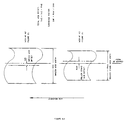
- a typical color bar, which is printed, in between the printed data is illustrated in Fig. 3.1.
- the ink density being laid down in the color bar is representative of the ink density being applied to the paper in the printed data portion.
- Good quality control dictates that the ink laid down in the printed data be of uniform density. Therefore, by measuring and controlling the density of the color bar, the invention is controlling the density of the printed data.
- the amount and location of ink to be put down on the web is preset at a color console 21, so that the console 21 automatically sets the servomotors 16 via a distribution microprocessor 22. In that way the inking units 11-14 have the proper gap to allow the right amount of ink to come through.
- These initial ink feed settings may be determined prior to the start up of the press. This is done by optically scanning the printing plates (not shown) beforehand to determine the apparent density for each representative color.
- the color density of the ink laid down on the paper web W should be maintained constantly throughout the run.
- a system 31 is provided. Basically, what the system 31 does is read the densities of the ink patches. When there are variations it tells the ink control console 21 how much to adjust in order to maintain the preset levels.
- system 31 includes a scanning means 32 to traverse the web W for scanning the color bar figure 3.1 Since data may be printed on both sides of the web W, scanning means 32 will be mounted on both sides of the web W.
- the dual scanning means can function independently of one another.
- the scanning means 32 ( Figure 2.2) is coupled to a belt 33 and is driven across the web W on a linear track 34 by an incremental stepper motor 45 which is capable of moving the scanning means 32 in 0.0381 cm (0.015 inch) increments across the web W.
- the scanning means 32 further includes: a strobe light 35 with associated electronics 36 for illuminating a color patch P in the color bar C (figure 2.1); an r.g.b. (red, green, blue) c.c.d. (charge couple device) camera 37 for photographing the illuminated color patch P; and a light guide and diffuser 43.
- the scanning, illumination and diffuser apparatus ride on a carriage assembly 39 on track 34.
- Rail guide chassis 40 provides mechanical support for the scanning means.
- the cover 41 is shown in removed position.
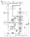
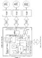
- FIG. 3.7 is an illustrated block diagram of the closed loop ink system 31 including its communications links.
- Closed loop operator workstation A is the main operator terminal. It houses the operator workstation computer 56, image processor computer 55, and the power regulation transformer.
- a graphical user interface incorporating a Sony VGA monitor and touch screen is employed for data entry and system control.
- the operator workstation computer is an Intel 80486 based personal computer. It is connected to the graphical user interface, image processor, and ink control console H. Ink density values are sent from the image processor to the operator workstation computer via an RS-485 serial link.
- the operator workstation computer displays these density values on the graphical user interface and transmits any necessary control signals to the ink control console H via serial link I.
- the electrical protocol of serial link I is dependent on the manufacturer of the ink control console H. In the case of a Perretta P2100A ink control console, serial link I would be an RS-485 twisted pair.
- the image processor communicates with the camera control processor 52 through a separate RS-485 serial link F as well as some discrete conductors (not shown) used for image acquisition handshaking. Also, video signals generated by an acquisition are transmitted to the image processor via multiple coaxial cables K.
- the camera control processor 52 communicates with the infeed controller D through RS-485 serial link G. Power is supplied to the entire system by the output of a 1KVA regulation transformer (not shown) in the base of the operator workstation.
- the regulated 115 volts AC are transmitted via conductors J to the power supply box C.
- Power supply box C houses the high voltage strobe power supplies, stepper motor power supplies, and the camera control processor logic power supply.
- the regulated 115 volts AC is transmitted from this box to the infeed controller D via conductors M. Strobe light, stepper motor and logic power are transmitted via conductors L to the rollstand B.
- the video data stored in framegrabber memory must be read by the image processor and manipulated before a new image overwrites it. This is accomplished by the image processor transmitting an active low busy signal L via conductors to the camera control processor 52 while the memory manipulation and calculations take place.
- Busy signal L is connected to the circumferential positioning card in the camera control processor. It is gated with the source of trigger pulse D using a Gould PEEL 18CVB programmable logic device so that a new trigger pulse D is not allowed while the busy line is low. Thus, a new acquisition cannot begin until the busy signal is high.
- the camera control processor controls: the video acquisition; camera head 32 lateral positioning; trigger mark detector lateral positioning; trigger mark detection; edge detector 61 positioning; edge detection and evaluation; communications with the infeed controller; and communications with the image processor 55.
- Figure 3.5 is a block diagram of the camera control processor 52.
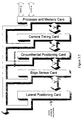
- Figure 3.2 is an illustration showing the various modular cards that make up the camera control processor. It is comprised of: a passive backplane; processor and memory card; camera timing card; circumferential positioning card; edge sensor card; and lateral position card. All cards and the passive backplane are custom designed but employ commercially available components.
- the passive backplane consists of a printed circuit card with a series of DIN 41612 compliant connectors soldered to it. Each connector has 64 contacts. The first 44 contacts carry common signals between all of the connectors. These signals consist of address/data lines, power and control signals such as read write and interrupts. The remaining 20 contacts are used for board specific input/output signals. These input/output signals are brought out to screw terminals and other connectors for interfacing to the various system components.
- the card adjacent to the processor and memory card is the camera timing card.
- This card consists of a series of Intel 8254 counter units; various input and output buffers; and system bus interface logic.
- the card produces all camera timing and video acquisition signals. It also produces the signals necessary to fire the Xenon strobe lights. All signals generated on this card are initiated by the rising edge of the circumferential trigger pulse D.
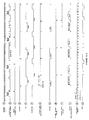
- the camera 32 requires only two input signals other than power. Referring to Figure 3.3, they are the horizontal drive clock K and the vertical drive pulses G. Both horizontal drive and vertical drive conform to the EIA RS-170A video signal standard. Both cameras operate identically. Therefore, waveforms and schematics only illustrate one drive system.
- Mode 2 is described as a rate generator in the Intel literature.
- a count equal to 262 horizontal periods is written into counter one's count register.
- a single active low pulse is generated and the count restarts.
- the waveform C with a period of 262H is generated by counter one.
- This count is the vertical drive period as defined by EIA RS-170A.
- the output of counter one is gated with the duration pulse of counter two and fed into the gate of counter zero. This assures that only two vertical drive pulses occur even though the output of counter one is continuos.
- Counter zero is setup in mode 1. This counter produces an active low pulse equal to 9 horizontal drive periods every time the gate is active. This sequence produces waveform D.
- the rising edge of signal E causes the framegrabber to capture and store the next video field. Because the framegrabber is an intelligent card plugged into the image processor input/output bus, the image processor is not automatically affected by the video acquisition sequence. The image processor itself must be signaled when the image acquisition is complete. However, the framegrabber has no provision to signal the host computer. Therefore, the camera control processor must generate the signal. This signal must be active after the entire video signal has been captured and stored by the framegrabber. This occurs approximately 32.274 milliseconds after the rising edge of trigger pulse D. An Intel 8254 counter unit on the camera timing card is set to mode 1 with a count equal to the duration of the video signal loaded into the count register. The count is initiated by the rising edge of trigger pulse D. The resulting waveform F is transmitted via conductors (not shown) and read by the image processor through an input port. The rising edge of waveform F signifies that the entire video field has been stored in framegrabber memory and may now be read by the image processor.
- the count is initiated by the rising edge of the trigger pulse D ( Figure 3.3).
- the output H of the 8254 counter unit goes low for a count of 100 horizontal time periods and then goes back high.
- the strobe pulse H is connected to the data input of a 7474 flip flop.
- the clock input of the flip flop is connected to the source of the vertical drive pulses G. Therefore a logic low is clocked into the flip flop during the first vertical drive pulse. This produces no change on the output.
- the second vertical drive pulse clocks a high logic level into the flip flop. This produces a change on the outputs of the flip flop.
- the non-inverted output (signal I) of the flip flop is sent via conductors to the lateral position card to initiate movement of the camera head to the next patch.
- the falling edge signal on the inverted output of the flip flop is used to trigger the strobe light. This falling edge is transmitted via conductors (not shown) to the trigger input of the high voltage power supply.
- the high voltage power supply generates a 200 volt DC output pulse which is sent via conductors (figure 3.7 L) to the high voltage strobe trigger transformer 42 ( Figure 2.2).
- a constant 600 volt DC is supplied by the high voltage power supply to the capacitor board 36 and the Xenon flashtube 35.
- the 200 volt trigger pulse is stepped up to 6,000 volts by high voltage strobe trigger transformer.
- This voltage is applied to the high voltage trigger plate 44 located behind and centered on the flashtube.
- the high voltage pulse excites the internal gases of the Xenon flashtube. This allows the 600 volts, stored in capacitor board 36, to discharge through the Xenon flashtube. In turn, this produces a short duration high intensity light pulse.
- the light pulse is guided through and diffused by a light guide, figure 2.2.
- the light beam is projected onto the moving web in the correct pattern and the correct angle.
- the strobe electronics in the camera head are minimal.
- the strobe power supply is remotely located. This reduces electromagnetic interference in the camera head to a negligible amount. Also, the weight of the head is minimal allowing fast acceleration/deceleration cycles needed to scan the moving web.
- a high degree of consistency means that the color patch is acquired and its resulting data is accurate enough to be used to control printed ink density.
- a high degree of synchronization precision is needed to consistently stop the action of the moving web with the color patch centered in the field of view. This high degree of precision is achieved by the system comprising of a: trigger mark detector 51; camera control processor 52; optical encoder 53; web driven roller 54; and trigger mark T. All are depicted in Figure 2.1.
- Camera control processor 52 applies direction and position pulses to a stepper motor system (not shown) to position the trigger mark detector 51 above the expected path of travel of the trigger mark T.
- Trigger mark sensor 51 is a SICK OPTIC NT816412 electro-optical sensor. It's output goes to a logical high level whenever an image, such as a trigger mark, darker than the background travels under it's sensing beam. Therefore, for every mark of print, such as a trigger mark, traveling orthogonal to, and under the sensor 51, an active high level signal is produced. The output signal returns to a low level when the data under the sensor is no longer darker than the background This happens when the trigger mark moves on and only the blank web W is under the sensing beam.
- the width of the active high pulse is directly proportional to the width of the mark or data that passed under the sensor.
- This active high pulse is input to the circumferential positioning card figure 3.2 in the camera control processor 52.
- the output of the web driven encoder 53 is also input to the circumferential positioning card figure 3.2.
- Encoder 53 is an IVO model G1350020B135 high resolution optical shaft encoder capable of outputting as many as 20,000 pulses per revolution.
- the encoder 53 is mechanically coupled to the 6 inch diameter web driven roller 54.
- Roller 54 is in close proximity to the camera heads 32 and the trigger mark detector 51. This allows the invention to compensate for any type of web distortion that has occurred prior to reaching the scanning unit. Because all sensors and the camera heads are in close proximity, no detectable distortion can occur between trigger mark detector 51 and the camera heads 32. This allows the invention to measure distances with an accuracy of up to plus or minus 0.0023936 cm (0.0009424 inches).
- the busy line is low whenever the image processor 55 is evaluating an image or the camera is in motion.
- the busy line is high and a valid trigger pulse C is generated, it is transferred to the gate input of the 8254.
- the 8254 is programmed to mode 5.
- Mode 5 is a hardware triggered one-shot mode. In this mode, the count is reset and initiated by the rising edge of a signal applied to the gate input. The output pin is initially high and then goes low for one clock count upon expiration of the count loaded into the count register.
- the offset count is input at the operator workstation 56 by the operator. The offset count is equal to the distance from the trailing edge of the trigger mark to the center of the color bar C. When the operator starts the system this parameter is sent via RS-485 serial link to the image processor.
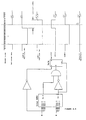
- Figure 3.9 illustrates the circuitry located in the sensor head 61.
- the sensor itself is a TSL216 opto sensor available from Texas Instruments.
- the sensor comprises of a linear array of 192 sensor elements referred to as pixels as well as the underlying drive circuitry.
- the pixel spacing is 0.005 inches.
- the sensor requires that a pixel clock A and start integration pulse B be input to it for proper operation.
- the sensor then generates an output that is an analog value of each pixel.
- Each analog value is shifted out of the TSL216 consecutively generating waveform C.
- the magnitude of each analog value is proportional to the amount of light striking the corresponding pixel.
- the sensor generates an end of conversion pulse F which indicates that all of the pixels have been transferred out of the sensor and a new integration period can begin.
- Pixel clock A is generated by an Intel 8254 counter unit. It is located on the edge detector board ( Figure 3.11) and is set in mode 3. Mode 3 is described by Intel as the square wave mode. In this mode, a count is loaded into the count register and the count begins. When half of the count has expired, the output goes from high to low. Output returns high when the second half of the count expires. The sequence repeats continuously. Thus, a 4 megahertz system clock generated by the microprocessor and memory card is applied to the clock input of the counter. A value of 16 is loaded into the count register. This produces a 250 kilohertz square wave which is the pixel clock A.
- the pixel clock is connected via conductors directly to the Texas Instruments TSL216 opto sensor.
- the interval between start integration pulses B defines the integration period of the sensor.
- the application of the start integration pulse to the TSL216 causes the analog data C from the last integration period to be output from the sensor.
- the analog data C is fed to the non-inverting input of an LM339 comparator.
- the inverting input is fed by a voltage divider which sets up a threshold voltage of 2 volts. Whenever the pixel data C is above this 2 volt threshold, the output of the LM339 goes to a high logic level. Whenever the pixel data C is below 2 volts, the output of the LM339 is a logic low.
- the 80C188EB has two counter inputs. Therefore, one sensor is connected to channel 0 and the other sensor is connected to channel 1.
- the end of conversion output from the TSL216 is connected to the edge detector card also. It is buffered and connected via the system bus to an interrupt input on the 80C188EB.
- the process control software reads the two counters to determine the number of exposed pixels.
- the light source A is an infrared LED connected to the 5 volt logic supply through a current limiting resistor.
- An infrared light filter is applied over the face of the opto sensor B so that it will not be affected by normal ambient light.
- the edge detectors 61 Upon system startup, the edge detectors 61, are driven towards the home limit sensors.
- the limit sensors are connected to an input port on the edge detector card.
- the microprocessor and memory card monitors the limit switch status. When a limit is sensed, the microprocessor controller stops sending drive signals to the stepper motor drive. When both sensors have reached their respective limit sensors, the sensors are calibrated. During calibration the sensors' exposure time is adjusted by lengthening the interval between start integration pulses until all pixels have been illuminated by the infrared light source. This compensates for degradation of the light source as well as any build up of dirt and dust on the sensors' face.
- the sensors are then moved towards the web one step at a time. In between each step the edge detector is read to check for the edge of the web.
- the step count is stored in the microprocessor controller's volatile memory and another step is taken.
- the total number of steps made by the stepper motors system is accumulated in the microprocessor controller's volatile memory.
- One count is kept for the right side sensor and one count is kept for the left side sensor.
- the pixel count is less than the total number of pixels the sensor is at the edge of the web.
- the stepper motor continues to step towards the web until approximately half of the sensor is exposed.
- the pixel count is added to the step count to determine the position of the edge of the web with respect to the home sensor. This dimension is calculated for both sides of the web.
- FIG. 3.10 is an illustration of the infeed control system.
- the edge detectors 61 and all drive electronics are identical to that of the roller stand and camera control processor.
- the dimensional data derived from the edge detectors 61 is used by the camera control processor to accurately find the center of the printed image, thus the center of the color patches, on the printed web W. This is necessary because the printed data may not always be centered on the web. Also, the web may have changed in width due to the printing, heating, and cooling processes.
- the infeed system comprises: an infeed controller box I, and an infeed sensor bar J.
- the infeed controller box I further comprises: a power supply A for logic level power to the infeed controller D; a power supply B for the generation of power for the stepper motors E; motor drivers C for interfacing between the logic level signals of the computer D and the stepper motors E; and infeed controller D.
- Infeed sensor bar J further comprises: incremental stepping motors E; edge detectors 61; limit sensors F; motor control cable G; and sensor cable H.
- Sensor bar J is identical to the sensor bar located in the roller stand B ( Figure 3.7).
- Infeed controller D is made up of the same microprocessor and memory card and edge sensor card used in camera control processor 52.
- the infeed controller is only responsible for the positioning and reading of the edge detector data and transmission of the resulting data to the camera control processor. Therefore, the passive backplane is slightly different than the one used in the camera control processor. It has only enough connectors for the microprocessor and memory card and the edge sensor card.
- the edge detector process control software is the same as that of the camera control processor 52.
- Cable H connects all signals relating to the sensor 61 to the infeed controller. Cable G carries the output of motor drivers C to the stepper motors E.
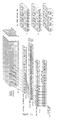
- the Color Bar Patch Layout array (Data Structure Diagram figure 5.1) is arranged by the user at the system work station, to match the layout of the Actual Printed Color Bar, by assigning one of the pre-defined Ink Zone Definitions (Data Structure Diagram figure 5.1) to each ink zone.
- An ink zone is defined as an 8 patch block whose position is relative to a printing press ink key in a printing press ink fountain. The number of ink zones is dependent upon the printing press width and ink fountain key size.
- Ink Zone Definitions may assign Color 1, 2, 3, 4 in a different sequence or that the colors will be defined as special colors other than Cyan, Magenta, Yellow and Black. Regardless of the color assignment however, Color 1,2,3,4 will always be placed at indices 0, 2, 4, 6 respectively. Tones and paper patch assignments are defined at indices 1, 3, 4, 7.
- the Patch Map (Data Structure Diagram figure 5.1) is an array parallel to the Color Bar Patch Layout.
- the binary bit state of each Patch Map element is a flag indicating that the corresponding color patch will be used. If an element in the Patch Map array is set to 1, then the corresponding element in the Color Bar Patch Layout will be included in the generation of the Scan Map array, otherwise the corresponding patch will be ignored.
- the user configured Color Bar Patch Layout array, Patch Map Array along with the Ink Zone Definitions are sent from the work station to the image processor via an RS-485 network.
- a copy of the arrays and definitions are sent to the camera controller from the image processor via an RS-485 link.
- Both the image processor and the camera controller use the two parallel arrays, the Ink Zone Definitions and an empirically derived sequence algorithm to calculate the scanning sequence.
- the sequence of patch numbers representing the path and pattern of the scanning sequence is stored in the Scan Map array.
- the sequence algorithm is defined as follows:
- An additional data structure is created in the image processor memory that stores indices of physical patch locations that are used by the image processor as it controls and processes the scan sequence.
- the indices point to patches in the Actual Printed Color Bar.
- the data is defined as follows:
- the Scan Map algorithm defines the following: 1) The sequence algorithm governs the color sequence to be followed; 2) The first patch number to be scanned, in the first half of the pass, is defined by the first_solid patch number; 3) the first patch number to be scanned, in the second half of the pass, is the first occurrence of color 3 that follows the first_solid patch number; 4) Colors 1 through 4 are located at every other patch number, starting at index 0 of each ink zone; 5) Tones and paper patches are located at every other patch number, starting at index 1 of each zone.
- the Scan Map is created for the first half of the first pass by placing the first_solid patch number at index 0 of the Scan Map. Stored at each successive index of the Scan Map is the previous patch number incremented by 2. The process is continued until the value stored in the Scan Map reaches the last_solid patch number.
- the first_yel patch number is stored at the next Scan Map index.
- the previous patch number is incremented by 2 for Color 3 and by 6 for Color 4 and stored.
- the second half of the second pass starts by storing the patch number of the tone or paper patch that occurs immediately prior to the last_solid patch number at the next Scan Map index.
- the previous patch number is decremented by 2 and stored in the Scan Map.
- the Scan Map data is complete.
- additional information is needed in conjunction with Scan Map to coordinate the retrieval and processing of data coming from the camera.
- the image processor can determine the Scan Map index that will be used to indicate which pass is being performed within a scan.
- index 23 of the Scan Map is the point where pass 1 will be completed
- index 31 is the completion of pass 2A
- index 39 is the completion point of pass 2B.
- the indices of pass 1, 2A & 2B will be referred to as pass indicators.
- the picture information is digitized and stored in 3 separate memory planes representing the primary color components.
- RGB red, green, blue
- a memory plane is organized as a matrix of 1024 x 1024 picture elements (pixels) where each pixel represents an intensity value with a range of 0 through 255. Pixels that have a value of 255 represent the highest intensity of a color. Conversely pixels having a value of 0 represent the lowest intensity of color.
- the RGB values of the actual video 'picture' acquired by the camera are stored in each respective memory plane as a 640 x 480 matrix starting at coordinate 0,0.
- the area of interest within the matrix from which the color samples will be read originates at coordinates 304,216 and is 32 x 48 pixels in size. Given a total camera field of view of approximately 0.635 cm (0.250 inches) the physical size of the area sampled is approximately 0.0508 cm (0.020") high by 0.0508 cm (0.020") wide.
- the pixel data within the sample area of each color plane is moved from the frame grabber memory to the image processor memory for processing.
- Each block of RGB pixel data is stored in its own respective 32 x 48 sample matrix.
- RGB data for the overall 640 x 480 matrix remains unaltered in frame grabber memory.
- the average intensity of a particular color's sample matrix is computed by summing all the values within the 32 x 48 sample matrix and then dividing by the total number of pixels summed.
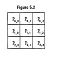
- the example 3 x 3 matrix (figure 5.2) contains 9 pixels.
- To obtain the average intensity of the example matrix sum the elements P(0,0) + P(0,1) + P(0,2) + P(1,0) + P(1,1) + P(1,2) + P(2,0) + P(2,1) + P(2,2). Then divide the result by 9.
- To calculate the average intensity of the center column within the matrix sum P(0,1) + P(1,1) + P(2,1) and then divide the result by 3.
- the closed loop control system operates with a camera for each side of the web, the process description will describe a single camera since the second camera is a redundant process. Both cameras follow the scanning process concurrently.
- the scanning process is centrally controlled from the image processor.
- the operator By pressing a start button at the operator workstation, the operator initiates the transfer of the color bar mapping data followed by a unique command code, via the RS-485 network.
- the command code instructs the image processor to start the scanning procedure.
- the image processor sets the busy signal (L of figure 3.3) of the camera control processor to a low level through a standard 8 bit parallel output port. This signifies a 'busy' condition exists, in effect causing the camera control processor to ignore trigger mark signals.
- the color frame grabber is then initialized as follows:
- the image processor passes a copy of the bar mapping data to the lateral position card.
- a Scan Map and the pass indicators are calculated simultaneously by the image processor and the lateral position card.
- the image processor then instructs camera control processor to initialize the web edge detection system and lateral position card.
- the camera control processor responds with an acknowledgment that the initialization process is completed.
- the lateral position card responds by informing the image processor that the initial physical positioning of the cameras and the trigger mark sensor are completed.
- the camera Before the scanning process begins, the camera must be moved to a black solid color patch located near the center of the web.
- the target patch in the Actual Printed Color Bar would be patch number 22.
- the lateral position card is sent a command, via the RS-485 network, to move to the center solid black patch.
- the image processor sets the busy signal (L) to a high level. This allows the camera control processor to process a trigger mark signal and acquire a video frame.
- Signal F of figure 3.3 is monitored through a standard 8 bit parallel input port by the image processor. A rising edge signifies that a video acquisition is completed.
- the busy signal (L) is set low to disable further trigger mark signal processing.
- the area of interest (AOI) within the red, green, and blue frame grabber memory planes is processed for hue and intensity.
- Hue and intensity software and hardware functions are provided by the frame grabber manufacturer. Intensity is a magnitude of brightness of particular color. It is represented by a number ranging from 0 to 255 where 0 signifies no intensity and 255 represents the brightest intensity.
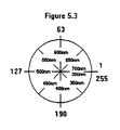
- Hue is a relative value that represents a color in the spectrum. Hue values (see figure 5.3) range from 0 through 255.
- An average intensity level of 50 or lower signifies that the sample is in fact a black patch.
- the left and right edge of the black patch is located using the following process:
- the actual longitudinal position of the camera, when the video was acquired can be calculated.
- Each pixel covers a field of view of approximately 0.001143 cm (0.00045").
- the width of the black patch can be computed by subtracting the left edge column coordinate from the right edge column coordinate and then multiplying the result with field of view dimension.
- the position of the memory plane AOI with respect to the center of the black patch video image is calculated as follows:
- the value computed in step #3 is the actual distance from the camera field of view center to the center of the black patch video image. If the computed distance is greater than 0.03048 cm (0.012"), the image processor sends a command via the RS-485 network to the lateral position card, instructing it to move toward the center by the amount of the computed distance. The sign of the correction value determines the direction the camera needs to travel.
- the actual process of scanning the Actual Printed Color Bar can begin.
- a 'run' command is sent from the image processor to the lateral position card. From this point, each time the image processor drives the busy signal (L) to a high level, a trigger mark signal is processed by the camera control processor and a video image is acquired.
- the lateral position card will also position the camera at the next patch number indicated in the Scan Map after the video acquisition. The scanning process will continue until a 'stop' command is received by the image processor from the operator workstation.
- the image processor may also receive a 'stop' command from the camera control processor for exceptions such as control system failures or printing press problems.
- a densitometers spectral response is the product of spectral power distribution of the lamp, attenuation of the optics and filters, and the spectral response the detector used.
- the reflectance factor is the ratio of the reflected flux from the sample material to the reflected flux from a perfect reflecting diffuser.
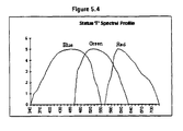
- a Status 'T' response was defined to closely match characteristics of graphics arts materials normally used in the United States such as ink-on-paper printed materials, oft-press proofs and original art to be color separated.
- the status 'T' response consists of a red, green, and blue filter set whose response is determined by a combination of the filter, the detector and the light source, and must conform to the curve defined in figure 5.4.
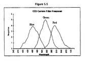
- the figure 5.5 response curve is defined by the manufacturer of the CCD camera. It represents the combined response of a 3200° K halogen light source, red-green-blue filters and a CCD sensor. An adjustment in the camera is provided by the manufacturer allowing for color balancing when using light sources of different color temperatures such as a stroboscopic flash tube.
- the Xenon flash tubes peak response is in the blue/green region, creating a color imbalance that exceeds the cameras color balance compensation capabilities.
- a 455nm optical filter is added to the camera lens to attenuate the level of blue light the camera sensor is exposed to.
- the camera's blue color balance adjustment is used to fine tune the peak amplitude of the blue output to match the status 'T' blue peak level. Green peak levels are equal and require no adjustment.
- the camera's red color balance adjustment is boosted to match the status 'T' red peak level. Bandwidths for the camera's filter/sensor response are narrower than the status 'T' definition at the red and blue extremes. Bandwidth compensation is performed in the density calculation software process.
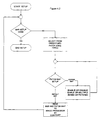
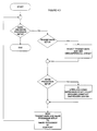
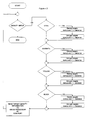
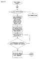
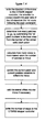
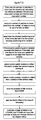
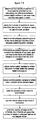
- the density calculation software process is performed after each image acquisition as illustrated by the scanning process flow chart.
- the process ink color of the patch image stored in the frame grabber memory planes is determined.
- the red, green, and blue memory plane AOIs are moved from frame grabber memory to their respective matrices in image processor memory.
- the hue and intensity value of the composite RGB color is calculated.
- the intensity level of each individual memory plane AOI is calculated.
- the current color being analyzed determines which color memory plane AOIs are to be used to determine the reflectance.
- Printing process colors have the following characteristics:
- CYAN ink filters red and passes mostly green and blue light. Looking at the CCD spectral response graph, it can be seen that the red response region is overlapped by a portion of the green region and a small portion of the blue region. To obtain the reflectance factor for CYAN, ideally the integral value of the red memory plane AOI would be used. Since the green and blue responses overlap the red response, a proportional amount of their values are used to compensate for bandwidth differences between the CCD camera response and the status 'T' response curves.
- reflectance factor ((red weight * average red memory plane AOI intensity)/250) + ((green weight * average green memory plane AOI intensity)/250) + ((blue weight * average blue memory plane AOI intensity)/250).
- the number 250 is the output value established for the red, green and blue outputs when reading the 98% neutral white calibration standard.
- Weights for each colors RGB filter response were determined empirically by comparing density readings from an industry standard status 'T' densitometer to the readings obtained with the CCD camera.
- red, green, and blue weights are set as follows:
- red, green, and blue weights are set as follows:
- red, green, and blue weights are set as follows:
- the calculated reflectance factor for the current patch is then plugged into the industry standard reflectance density formula and the result is stored in the Patch Color Density matrix.
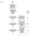
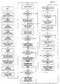
- a flowchart (figure 5.8) describes the software process for density processing.
- First location is the infeed sensor assembly 62 of Fig. 2.1, located before the first inking unit 11.
- Second location is the roller stand sensor assembly 63, located on the roller stand before scanning means 32.
- Each sensor assembly consists of two edge detectors 61.
- Two parameters of the web are measured at both locations. These are web width and web position relative to center of the printing Fig. 6.1.
- edge detectors 61 move from home position to the center of the press until they sense the edges of the web fig. 6.3 and 6.4.
- the web width WW and web offset WO measured at 62 of Fig. 2.1 before the first inking unit are sent to the roller stand as infeed web width IWW and infeed web offset IWO .
- a second set of web parameters are measured at 62 of Fig. 2.1. These are roller stand web width RWW and roller stand web offset RWO .
- SHF shrinkage factor
- IWW/RWW the ratio of web width before the first inking unit and the web width at the roller stand.
- STF IWW/RWW .
- Total web offset, figure 6.2, TWO and step factor STF are constantly monitored during the control process.
- the first samples of TWO and STF are taken as valid samples. If there is a significant difference (greater then 0.02286 cm (0.009 inches)) between the latest sample and the valid sample of the total web offset, then the latest sample value of TWO is taken as the valid sample of TWO . It is sent to camera control processors lateral position card 52 of Fig. 2.1 to correct lateral position of scanning means 32 during a scan. Also the latest sample of step factor STF is taken as valid. It is sent to camera control processor's lateral position card 52 of Fig. 2.1 if the difference between the last sample and valid sample of STF is greater then 0.00381 cm (0.0015 inches).
- Precise lateral positioning of the camera head and trigger mark detector is accomplished with a stepper motor system figure 7.1.
- the system consists of: a Lateral Position Card 7.1 housed in the camera control processor figure 2.1 52; three standard SGS-Thompson GS-D200S stepper drivers; three conventional 1.8 ⁇ SLO-SYN stepper motors (two of Type M063-CE06 for the camera heads; and one of type M062-CE04 for the trigger mark detector); and six Omron photo detectors (EE-S G3M) figure 7.1.
- the camera head stepper motors are connected to a belt driven carriage figure 2.2.
- the trigger mark detector motor is also operating in half step mode but it is connected to a 2.9108 cm (1.146") pitch diameter timing gear. This arrangement yields a 0.2286 cm (0.009 inch) step size for the trigger mark detector positioning.
- the task of the lateral position card figure 7.1 is to provide positioning information to the top camera head and bottom camera head stepper drivers.
- the two camera heads operate independently of one another. It also provides positioning information to the trigger mark detector stepper driver. Included in the information is compensation for print positional changes with respect to the center of the roller stand.
- Positioning information includes: step motor pulses, motor direction signals, and motor torque signals.
- the lateral position control software requires initialization information from the operator workstation and the image processor.
- the operator workstation provides: roller stand center dimensions, the number of ink zones, and the width of an ink zone.
- the image processor sends a scan map figure 5.1. The map defines the pattern in which the camera heads will scan the actual printed color bar.
- the card is located in the camera control processor on the remote I/O bus figure 3.5.
- An 8 bit Hitachi HD647180 microprocessor controls the card. External to the microprocessor are, 32Kbytes of 62256 RAM (Random Access Memory), and 32Kbytes of 27256 ROM (Read Only Memory), for program and data storage. Communications to the card is via a RS-485 interface.
- the stepper motor system requires a method of accelerating the camera head mass up to a constant speed and decelerating the mass back to zero speed. This is accomplished by step motor pulses that are provided to the two camera head stepper motor drivers by two Cybernetics CY545B stepper controller devices.
- the devices are programmed by the control software to provide suitable running and ramping characteristics. Motor direction signals are also generated by the CY545B devices.
- the trigger mark detector motor step pulses are not ramped as are the step pulses to the camera head stepper motors.
- Motor step pulses and a motor direction signal to the trigger mark detector stepper motor driver are achieved by latching HD647180 data bus bits via a 74HC573 octal latch.
- Essential to the design of a stepper motor system is a means for providing high and low torque conditions to the motors. This is accomplished by latching the HD647180 data bus as torque signals, for all three stepper motor drivers, via a 74HC573 octal latch.
- step pulses, direction signals, and torque signals are buffered before exiting the card.
- the step pulses and direction signals are buffered through an open collector 74LS641 octal transceiver.
- the torque signals are buffered by a Texas Instruments open collector SN7407N buffer.
- the motion of both camera heads and the trigger mark detector are limited by limit sensors 46 figure 2.2.
- the limit sensors on the left side of the press are referred to as home sensors.
- the camera head limit sensors are tied directly to the HD647180 and to the CY5454B devices.
- the trigger mark detector assembly limit detectors are tied directly to the HD647180. Lateral motion is inhibited anytime a camera head or trigger mark detector activates the limit sensor.
- a key feature of the invention is the reliability of the stepper system to compensate for the lateral print positional variations quickly enough such that each image acquired is of the desired color patch.
- Three factors cause lateral print position variations. As the print is applied to the web, it may not be centered on the web. Also, as the web travels through the roller stand, it weaves laterally with an unpredictable magnitude and frequency. The web also shrinks in width due to being stretched and losing moisture from being heated by ovens.
- the first type is referred to as lateral offset. This is the offset of the center of the print from the center of the roller stand.
- the second type of information is referred to as step factor which is derived from the web shrinkage factor.
- the step factor is used to mathematically create a smaller motor step size in order to compensate for the print shrinkage. It represents the lateral distance of the print before shrinkage which will be traversed by the physical motion of the camera head after print shrinkage has occurred. Physically, one step of a camera head stepper motor always results in 0.0381 cm (0.015") of lateral movement. Prior to web shrinkage, 0.0381 cm (0.015”) of the original print is being traversed by one motor step. As the paper shrinks, one physical step of the camera head motor will traverse more than 0.0381 cm (0.015”) of the print prior to shrinkage.
- the control software calculates the number of steps and direction to move the camera heads and trigger mark detector based upon the difference of the two variables. Using the number of steps, the top_step_offset variable is updated to reflect the current distance of the camera head from center.
- top_step_offset ⁇ number of steps * step size , to within ⁇ one half the distance of one step from the new_offset dimension. Because of the small size of lateral offset, web shrinkage is negligible and is ignored. If a camera motion is not currently being made the offset is corrected immediately. If a camera motion is being made, the offset is added or subtracted to the end of the current move.
- stepper motor There is, inherent in physical constraints of a stepper motor, an error induced into the positioning of the camera heads and trigger mark detector. That error will be called the physical positioning error.
- the step size is not directly divisible into distance of the move. In other words, there is a fractional difference between the distance a stepper motor can move the camera heads or trigger mark detector and the distance they need to move. That fractional difference is stored in an error variable each time a movement is made. When the fraction accumulates in magnitude equal to a step of the motor, it is added to the next move and one step of motion is subtracted from the error variable. This insures that positioning is never off by more than a single step due to constraints of the stepper motor.
- a lateral position variable in the control software keeps track of the x dimension of the camera heads and the trigger mark detector.
- the x dimension is referenced to a home limit sensor located on the left side of the linear rail figure 2.2 which acts as a home position.
- commands from the image processor which cause lateral positioning of the camera heads to an x dimension. Those commands are: Move to Center, Move to X, and Move to Patch.
- the control software calculates the number of steps required to move the camera head or trigger mark detector from its current x dimension to the new x dimension. The position variable is updated during the calculation of steps. The number of steps is written to the CY545B, in the case of positioning a camera head, or to a 74HC573 latch, in the case of positioning the trigger mark detector.
- an active low busy signal is provided to the camera timing card figure 3.5.
- a Move to Home command issued by the operator workstation causes the camera head to move in the direction of the left side until the home detector is reached.
- the image processor is expecting a response following a completion of a command to Move to Center or Move to Home. At the end of the move, the card responds to these commands by transmitting the current patch number which the camera head is located at. A response is also expected following a trigger mark detector Move to X command or move to home. Upon the completion of these commands, the card transmits the current x position of the trigger mark detector.
- lateral motion of the camera head is initiated by an active low lateral move pulse I figure 3.3.
- the pulse is generated by the camera timing card.
- the lateral move pulse is connected to the HD647180 external interrupt INT1 (INT2 for the lower camera).
- INT1 INT2 for the lower camera.
- the control software determines how many patches to move the camera head from the scan map. Using the number of patches to move, a look up table in the control software determines how many steps are required to move to the next patch. The physical positioning error is compensated for in another look up table.
- the active low busy signal is provided to the camera timing card in the camera control processor. This prevents another video acquisition from occurring during movement.
- the busy signal is driven high (inactive) and the card is ready for another lateral move pulse.
- a camera head is positioned at the last patch of the scan map, it will loop back to the first patch in the map upon the next lateral move pulse. This process repeats until the controller is taken out of the scan mode by a lateral stop command issued by the operator workstation.
- a calibration procedure must be performed on the infeed and roller stand edge detectors.
- the purpose of the calibration procedure is to determine the distance from each home detector to the center of the press and the distance between the two home detectors.
- the calibration procedure is required because the infeed edge detector assembly figure 3.10 is a retrofit to the press and its position relative to the center of the press is not defined. Since the procedure is identical at both locations only one will be described.
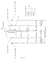
- a calibration bar figure 7.2 of known length is secured to the infeed edge detector assembly at the center of the press.
- the processor and memory card must be put into calibration mode by use of a switch on the card.
- the two edge detectors locate their respective home sensors, then locate the calibration bar.
- An LCD (liquid crystal display) on the processor and memory card will display the distance from the left and right home detectors to the center of the calibration bar. Those numbers are manually entered into the image processor as part of the installation procedure.
Landscapes
- Engineering & Computer Science (AREA)
- Quality & Reliability (AREA)
- Inking, Control Or Cleaning Of Printing Machines (AREA)
Claims (15)
- Dans une presse pour imprimer des données multicolores, à partir d'unités d'encrage sur une bande, au fur et à mesure que celle-ci est alimentée dans la presse, les données incluant une pluralité de barres de contrôle espacées, composées de taches de couleur déposées par l'une respective des unités d'encrage, s'étendant sur toute la largeur du papier et dans laquelle des moyens sont fournis pour contrôler la quantité d'encre alimentée à partir des unités d'encrage sur la trame, un système pour établir et/ou maintenir la densité des encres colorées déposées sur la bande en déplacement comprenant :des moyens de balayage comportant :des moyens formant stroboscope pour illuminer chaque tache de couleur de la barre de couleurs,des moyens formant caméra pour former une image de chaque tache de couleur etdes moyens d'entraínement pour déplacer les moyens formant stroboscope et les moyens formant caméra, de façon incrémentielle et transversale sur toute la bande ;des moyens de capture d'une image de chaque tache de couleur qui comportent des moyens d'activation et de désactivation des moyens formant caméra ;des moyens de synchronisation de l'actionnement des moyens de balayage ;des moyens de calcul de la densité d'encre de chaque tache de couleur imprimée ;des moyens pour calculer le réglage des unités d'encrage nécessaire pour maintenir la densité d'encre de chaque tache colorée imprimée :des moyens de réalisation du réglage des unités d'encrage nécessaire pour maintenir la densité d'encre de chaque tache de couleur imprimée ;des moyens de détection d'un déplacement latéral ou une distorsion de la bande comportant :des détecteurs de bord pour détecter la position latérale de la bande, le rétrécissement de la bande, la déformation de la bande ;des moyens de réglage de la position latérale des moyens de balayage, basés sur un signal envoyé par les détecteurs de bord, afin de maintenir l'alignement latéral correct entre la tête de balayage et une tache de couleur imprimée ;et des moyens de commande de processus logiciel pour le balayage, la synchronisation, l'actionnement, la détermination de la densité, le calcul du réglage des unités d'encrage, la commande du réglage des unités d'encrage et la détection du déplacement latéral de la bande.
- Système tel qu'il est défini dans la revendication 1 dans lequel les moyens formant caméra comprennent un dispositif à couplage de charges, rouge, vert et bleu, pour former une image de chaque tache de la barre de couleur imprimée.
- Système tel qu'il est défini dans la revendication 1 dans lequel les moyens de synchronisation comportent un capteur électro-optique destiné à détecter une marque de déclenchement imprimée et des moyens formant microprocesseur pour commander l'actionnement des moyens formant stroboscope et des moyens formant caméra ainsi que le déplacement latéral des moyens de balayage au moment de la réception d'un signal envoyé par le capteur électro-optique lorsqu'une marque de déclenchement est détectée sur la bande en déplacement.
- Système tel qu'il est défini dans la revendication 3, dans lequel les moyens de synchronisation comportent de plus un codeur optique rotatif couplé mécaniquement au déplacement de la bande qui fournit après chaque marque de déclenchement un comptage spécifique des impulsions de commutation aux moyens formant microprocesseur pour obtenir une synchronisation précise des moyens de balayage avec la position de la barre de couleur imprimée sur la trame en déplacement.
- Système tel qu'il est défini dans la revendication 1 dans lequel les moyens de synchronisation comportent des moyens formant microprocesseur pour commander l'actionnement des moyens de balayage et dans lequel les moyens de calcul de la densité d'encre comportent des moyens d'ordinateur pour calculer la densité d'encre sur la base d'un signal envoyé par les moyens formant caméra.
- Système tel qu'il est défini dans la revendication 1, dans lequel les moyens de calcul du réglage des unités d'encrage comportent des moyens d'ordinateur numérique de poste de travail d'opérateur pour effectuer le réglage des unités d'encrage via un signal de commande envoyé par l'ordinateur numérique de poste de travail d'opérateur.
- Système tel qu'il est défini dans la revendication 1, dans lequel les détecteurs de bord comportent deux capteurs situés au niveau des moyens d'introduction et deux capteurs situés au niveau d'un support de rouleau pour détecter la position latérale de la bande, le rétrécissement de la bande et la déformation de la bande.
- Système tel qu'il est défini dans la revendication 7, comprenant des moyens de microprocesseur pour interpréter les données de la bande latérale et la commande des moyens d'entraínement pour le positionnement latéral du stroboscope et de la caméra.
- Système tel qu'il est défini dans la revendication 1, dans lequel les moyens de commande de processus logiciel comprennent de plus des moyens qui comportent : des moyens de commande de processus logiciel pour l'actionnement des moyens formant stroboscope et des moyens formant caméra ; des moyens de commande de processus logiciel pour les moyens formant stroboscope et les moyens de capture d'image, des moyens de commande de processus logiciel pour le positionnement latéral des moyens de balayage ; des moyens de commande de poste de travail de processus logiciel ; une commande de processus logiciel pour déterminer le déplacement latéral ou la déformation de la bande et une commande de processus logiciel pour effectuer le réglage des unités d'encrage.
- Système tel qu'il est défini dans la revendication 9, dans lequel les moyens de commande de processus logiciel pour l'actionnement des moyens formant stroboscope et caméra comprennent de plus des moyens de logiciel pour mettre en oeuvre des fonctions de commande d'un détecteur de marque de déclenchement et pour commander des moyens pour obtenir une synchronisation précise des moyens de balayage avec la position de la barre de couleur imprimée sur la trame en déplacement.
- Système tel qu'il est défini dans la revendication 9, dans lequel les moyens de commande de processus logiciel pour les moyens formant stroboscope et de capture d'image par la caméra comprennent de plus des moyens logiciels pour mettre en oeuvre des fonctions de commande, un tableau de capteur page-écran et l'activation et la désactivation du processus de capture d'image.
- Système tel qu'il est défini dans la revendication 9, dans lequel les moyens de commande de processus logiciel pour la position latérale des moyens de balayage comprennent de plus des moyens de logiciel pour mettre en oeuvre des fonctions pour la commande du processus de balayage de la position latérale.
- Système tel qu'il est défini dans la revendication 9, dans lequel les moyens de commande de poste de travail de processus logiciel comprennent de plus des moyens de logiciel pour mettre en oeuvre des fonctions de commande : programmation du dessin des taches de la barre, carte des taches et commande de contrôle de distribution aux unités d'encrage.
- Système tel qu'il est défini dans la revendication 9, dans lequel les moyens de commande de processus logiciel pour déterminer le déplacement latéral ou la déformation de la bande comprennent de plus des moyens de logiciel pour mettre en oeuvre des fonctions de commande de détection du déplacement latéral de la bande et de détection de la déformation de la bande.
- Système tel qu'il est défini dans la revendication 1, dans lequel les moyens de calcul de la densité de l'encre de chaque tache de couleur imprimé comprennent des moyens de logiciel pour mettre en oeuvre des fonctions de commande pour convertir les valeurs rouge, vert et bleu (RVB) en une densité d'encre, l'évaluation de densité d'encre et la correction de densité d'encre.
Applications Claiming Priority (3)
| Application Number | Priority Date | Filing Date | Title |
|---|---|---|---|
| US141991 | 1980-04-21 | ||
| US14199193A | 1993-10-28 | 1993-10-28 | |
| PCT/US1994/011388 WO1995011806A1 (fr) | 1993-10-28 | 1994-10-11 | Systeme de maintien de la densite de l'encre |
Publications (3)
| Publication Number | Publication Date |
|---|---|
| EP0725733A1 EP0725733A1 (fr) | 1996-08-14 |
| EP0725733A4 EP0725733A4 (fr) | 1997-01-08 |
| EP0725733B1 true EP0725733B1 (fr) | 2000-05-17 |
Family
ID=22498122
Family Applications (1)
| Application Number | Title | Priority Date | Filing Date |
|---|---|---|---|
| EP95900357A Expired - Lifetime EP0725733B1 (fr) | 1993-10-28 | 1994-10-11 | Systeme de maintien de la densite de l'encre |
Country Status (5)
| Country | Link |
|---|---|
| US (1) | US5992318A (fr) |
| EP (1) | EP0725733B1 (fr) |
| JP (1) | JPH09507040A (fr) |
| DE (1) | DE69424559T2 (fr) |
| WO (1) | WO1995011806A1 (fr) |
Families Citing this family (54)
| Publication number | Priority date | Publication date | Assignee | Title |
|---|---|---|---|---|
| DE59708489D1 (de) * | 1997-02-19 | 2002-11-21 | Baldwin Germany Gmbh | Vorrichtung und Verfahren zur Durchführung von qualitätsmanagement |
| US6292182B1 (en) * | 1997-06-25 | 2001-09-18 | Hyundai Electronics Industries Co., Ltd. | Liquid crystal display module driving circuit |
| DE19802920B4 (de) | 1998-01-27 | 2008-01-31 | Man Roland Druckmaschinen Ag | Verfahren und Vorrichtung zur Farbregelung in Druckmaschinen |
| JP3384769B2 (ja) * | 1999-04-19 | 2003-03-10 | リョービ株式会社 | インキ供給量調整装置およびインキ供給量調整方法 |
| EP1060886B1 (fr) * | 1999-06-19 | 2002-07-31 | Koenig & Bauer Aktiengesellschaft | Procédé et dispositif pour alimenter en encre l'encrier des machines d'impression |
| DE10009661B4 (de) * | 1999-06-19 | 2007-10-04 | Koenig & Bauer Aktiengesellschaft | Verfahren und Einrichtung zum Zuführen von Druckfarbe in Farbkästen von Druckmaschinen |
| DE60020380T2 (de) * | 1999-08-31 | 2006-02-16 | Canon Finetech Inc., Mitsukaido | Verfahren und vorrichtung zum erfassen von druckmaterial, und drucker |
| DE29916379U1 (de) * | 1999-09-17 | 1999-12-09 | MAN Roland Druckmaschinen AG, 63075 Offenbach | Vorrichtung zum densitometrischen Ausmessen von Druckprodukten |
| US6874420B2 (en) * | 1999-10-22 | 2005-04-05 | Cc1, Inc. | System and method for register mark recognition |
| DE10141446A1 (de) * | 2000-09-18 | 2002-03-28 | Heidelberger Druckmasch Ag | Anordnung zum Detektieren von Registermarken |
| US6553906B1 (en) * | 2000-10-17 | 2003-04-29 | Nexpress Solutions Llc | Method and apparatus for sensing a register discrepancy in a multi-color printed item, and register control system and register marks |
| JP3560335B2 (ja) * | 2000-11-21 | 2004-09-02 | キヤノン株式会社 | ステッピングモータ制御装置およびその方法、ならびに画像読取装置およびその方法 |
| JP2002192700A (ja) * | 2000-12-26 | 2002-07-10 | Dainippon Screen Mfg Co Ltd | 印刷制御装置および記録媒体 |
| DE20122584U1 (de) * | 2001-03-27 | 2006-07-27 | Windmöller & Hölscher Kg | Einheit zur Einstellung des Druckbildes in einer Rotationsdruckmaschine |
| US20020162470A1 (en) * | 2001-05-04 | 2002-11-07 | Yoshikazu Shimamura | Press profile production method, color management method, printed sheet, and color management system |
| US7202973B2 (en) * | 2001-07-04 | 2007-04-10 | Dainippon Screen Mfg. Co., Ltd. | Patch measurement device |
| US7253929B2 (en) * | 2002-02-06 | 2007-08-07 | Quad/Tech, Inc. | Camera assembly for a printing press |
| US7013803B2 (en) | 2002-02-06 | 2006-03-21 | Quad/Tech, Inc. | Color registration control system for a printing press |
| JP2003311933A (ja) * | 2002-04-24 | 2003-11-06 | Dainippon Screen Mfg Co Ltd | パッチ測定装置およびそれを組み込んだ印刷装置 |
| US7187472B2 (en) | 2002-09-03 | 2007-03-06 | Innolutions, Inc. | Active color control for a printing press |
| US6938550B2 (en) * | 2002-10-31 | 2005-09-06 | R. R. Donnelley & Sons, Co. | System and method for print screen tonal control and compensation |
| DE10302747A1 (de) * | 2003-01-24 | 2004-08-12 | Windmöller & Hölscher | Verfahren zur Korrektur von im Druckprozess auftretenden Schwankungen der auf das Druckbild übertragenen Farbmenge |
| US7032508B2 (en) * | 2003-03-21 | 2006-04-25 | Quad/Tech, Inc. | Printing press |
| PL1673226T3 (pl) | 2003-09-12 | 2012-09-28 | Eyec Gmbh | Sposób i urządzenie do kontrolowania wyników drukowania |
| DE10361543A1 (de) * | 2003-09-12 | 2005-04-14 | Eyec Gmbh | Verfahren und Vorrichtung zum Prüfen von Druckergebnissen |
| JP4353107B2 (ja) * | 2005-02-18 | 2009-10-28 | コニカミノルタビジネステクノロジーズ株式会社 | カラー画像形成装置 |
| DE102005015972A1 (de) * | 2005-04-07 | 2006-10-12 | Man Roland Druckmaschinen Ag | Verfahren zur Einstellung der zonalen Farbgebung eines Farbwerks einer Druckmaschine sowie Farbwerk |
| US7477420B2 (en) * | 2005-09-07 | 2009-01-13 | Innolutions, Inc. | Barless closed loop color control |
| US7859668B2 (en) | 2005-12-15 | 2010-12-28 | Honeywell International Inc. | Apparatus and method for illuminator-independent color measurements |
| US8017927B2 (en) | 2005-12-16 | 2011-09-13 | Honeywell International Inc. | Apparatus, system, and method for print quality measurements using multiple adjustable sensors |
| US7688447B2 (en) | 2005-12-29 | 2010-03-30 | Honeywell International Inc. | Color sensor |
| US7573575B2 (en) | 2005-12-29 | 2009-08-11 | Honeywell International Inc. | System and method for color measurements or other spectral measurements of a material |
| EP1839854A1 (fr) * | 2006-03-31 | 2007-10-03 | ELTROMAT GmbH | Méthode et dispositif pour ajuster optimalement la position dans une machine d'impression rotative fléxographique |
| JP2008037046A (ja) * | 2006-08-09 | 2008-02-21 | Mitsubishi Heavy Ind Ltd | 印刷機の操作デスク |
| JP2008213366A (ja) * | 2007-03-06 | 2008-09-18 | Ryobi Ltd | 印刷機におけるカラーバーの色濃度測定方法及び印刷機におけるカラーバーの色濃度測定装置並びに色濃度測定装置を備えた印刷機 |
| US7592608B2 (en) * | 2008-01-22 | 2009-09-22 | Honeywell International Inc. | Apparatus and method for measuring and/or controlling ultraviolet-activated materials in a paper-making process |
| US8049892B2 (en) * | 2008-01-22 | 2011-11-01 | Honeywell International Inc. | Apparatus and method for camera-based color measurements |
| US8132887B2 (en) | 2010-03-02 | 2012-03-13 | Innolutions, Inc. | Universal closed loop color control |
| EP2368711B1 (fr) * | 2010-03-25 | 2012-12-05 | Modesto Luengo Bada | Marque, procédé et système pour la mesure des paramètres de qualité de la couleur |
| US9100620B2 (en) | 2010-05-25 | 2015-08-04 | Xerox Corporation | Method and system for adding a color bar as a rendering job ticket attribute |
| US8401809B2 (en) | 2010-07-12 | 2013-03-19 | Honeywell International Inc. | System and method for adjusting an on-line appearance sensor system |
| WO2012013759A2 (fr) * | 2010-07-28 | 2012-02-02 | Sms Siemag Ag | Dispositif de mesure et cage de laminoir ainsi que procédé d'exploitation des deux dispositifs |
| JP5468509B2 (ja) | 2010-10-08 | 2014-04-09 | 株式会社小森コーポレーション | 印刷機の制御装置および制御方法 |
| DK2471665T3 (da) * | 2010-12-30 | 2013-05-06 | Alltec Angewandte Laserlicht Technologie Gmbh | Markerings- og/eller scanningshoved, -indretning og -fremgangsmåde |
| US20130063587A1 (en) * | 2011-03-09 | 2013-03-14 | Curt G. Joa, Inc. | Apparatus and method for minimizing waste and improving quality and production in web processing operations by automatic narrow web twist defect correction |
| US9440425B2 (en) * | 2012-05-02 | 2016-09-13 | Advanced Vision Technology (Avt) Ltd. | Methods and systems for setting the pressure of the cylinders of the printing press without requiring special targets |
| DE102013208964A1 (de) * | 2013-05-15 | 2014-11-20 | Robert Bosch Gmbh | Registermarkensensor mit variabler Abtastrate |
| EP3003578A4 (fr) * | 2013-05-31 | 2018-02-21 | Rosenberg, Joe, I.v. | Procédé et appareil de conversion d'une presse d'impression à l'humide sans sécheur en une presse d'impression à l'humide avec sécheur et sans sécheur hybride |
| US9616657B2 (en) * | 2013-10-01 | 2017-04-11 | Goss International Americas, Inc. | Closed loop ink thickness control system with reduced substrate waste in a printing press |
| DE102015105656B4 (de) | 2015-04-14 | 2025-02-13 | Chromasens Gmbh | Steuermodul für eine Kamera, Kamera, Produktionssystem und Verfahren zum Erfassen von Bildern mittels einer solchen Kamera |
| MX2019000614A (es) | 2016-07-20 | 2019-07-04 | Ball Corp | Sistema y metodo para alinear un entintador de un decorador. |
| US11034145B2 (en) | 2016-07-20 | 2021-06-15 | Ball Corporation | System and method for monitoring and adjusting a decorator for containers |
| EP3740383A4 (fr) | 2018-01-19 | 2021-10-20 | Ball Corporation | Système et procédé pour surveiller et régler un dispositif de décoration pour récipients |
| CN109341645B (zh) * | 2018-12-14 | 2021-07-06 | 惠科股份有限公司 | 平整度测量治具和压合设备 |
Family Cites Families (8)
| Publication number | Priority date | Publication date | Assignee | Title |
|---|---|---|---|---|
| US4003660A (en) * | 1975-12-03 | 1977-01-18 | Hunter Associates Laboratory, Inc. | Sensing head assembly for multi-color printing press on-line densitometer |
| DE3309443A1 (de) * | 1982-05-29 | 1983-12-08 | Heidelberger Druckmaschinen Ag, 6900 Heidelberg | Verfahren zur ermittlung der flaechendeckung einer druckvorlage oder druckplatte fuer druckmaschinen |
| DE3220360A1 (de) * | 1982-05-29 | 1983-12-01 | Heidelberger Druckmaschinen Ag, 6900 Heidelberg | Einrichtung zur beeinflussung der farbgebung an druckmaschinen |
| EP0127831B1 (fr) * | 1983-06-02 | 1990-03-14 | Web Printing Controls Co. | Dispositif de repérage à boucle fermée |
| US4794453A (en) * | 1986-09-09 | 1988-12-27 | Web Printing Controls Co. | Method and apparatus for stroboscopic video inspection of an asynchronous event |
| DE3804941A1 (de) * | 1988-02-17 | 1989-08-31 | Hell Rudolf Dr Ing Gmbh | Verfahren und einrichtung zur erfassung von druckflaechendeckungsdaten |
| DE3812099C2 (de) * | 1988-04-12 | 1995-01-26 | Heidelberger Druckmasch Ag | Verfahren zur Farbsteuerung einer Offsetdruckmaschine |
| DE3830731A1 (de) * | 1988-09-09 | 1990-03-22 | Heidelberger Druckmasch Ag | Vorrichtung zur farbmessung |
-
1994
- 1994-10-11 JP JP7512653A patent/JPH09507040A/ja active Pending
- 1994-10-11 US US08/738,193 patent/US5992318A/en not_active Expired - Fee Related
- 1994-10-11 DE DE69424559T patent/DE69424559T2/de not_active Expired - Fee Related
- 1994-10-11 EP EP95900357A patent/EP0725733B1/fr not_active Expired - Lifetime
- 1994-10-11 WO PCT/US1994/011388 patent/WO1995011806A1/fr not_active Ceased
Also Published As
| Publication number | Publication date |
|---|---|
| DE69424559D1 (de) | 2000-06-21 |
| US5992318A (en) | 1999-11-30 |
| WO1995011806A1 (fr) | 1995-05-04 |
| EP0725733A4 (fr) | 1997-01-08 |
| EP0725733A1 (fr) | 1996-08-14 |
| JPH09507040A (ja) | 1997-07-15 |
| DE69424559T2 (de) | 2001-01-18 |
Similar Documents
| Publication | Publication Date | Title |
|---|---|---|
| EP0725733B1 (fr) | Systeme de maintien de la densite de l'encre | |
| EP0741032B1 (fr) | Dispositif de mesure de la densité réflective et système de contrôle pour une machine à imprimer des bandes | |
| US7187472B2 (en) | Active color control for a printing press | |
| US6119594A (en) | Method for regulating inking during printing operations of a printing press | |
| US5791249A (en) | System and method for regulating dampening fluid in a printing press | |
| US6499402B1 (en) | System for dynamically monitoring and controlling a web printing press | |
| US8132887B2 (en) | Universal closed loop color control | |
| JP5715229B2 (ja) | 異なる動作をする2つの測定装置を備えている、色に関する測定を行う装置 | |
| US20080055355A1 (en) | Replicated multi-channel sensors for decucing ink thicknesses in color printing devices | |
| US6086274A (en) | Line printer for the digital output and colorimetric measurement of colored images | |
| JPH0829582B2 (ja) | 印刷機の前調整装置 | |
| US7477420B2 (en) | Barless closed loop color control | |
| US6201559B1 (en) | Method for measuring the quantity of light emergent from an optical tip array and image forming apparatus provided with an optical tip array | |
| US4555180A (en) | Printed area measuring apparatus | |
| JP3769895B2 (ja) | 画像形成装置 | |
| US6388694B1 (en) | Method for calculating the output characteristic of an optical tip array and image forming apparatus | |
| US20010006212A1 (en) | Solid scanning optical writing device, and light amount correction method and light amount measuring device therefor | |
| JP3374687B2 (ja) | 固体走査型光書込み装置及びその光量測定方法 | |
| EP0919883B1 (fr) | Module de balayage à laser et procédé pour le synchroniser | |
| EP1375164B1 (fr) | Imprimante fluorescente à vide | |
| EP1262323B1 (fr) | Système pour surveiller et de controller dynamiquement une machine à imprimer des bandes | |
| JP2006301001A (ja) | プリント装置及び補正データ生成方法 | |
| JPH04351554A (ja) | 平台校正機の自動インキ供給装置 | |
| JPH10272761A (ja) | 印刷物の色調変動制御装置 | |
| JPH09300589A (ja) | 巻帯体印刷機用のダイナミック反射密度測定及び制御システム |
Legal Events
| Date | Code | Title | Description |
|---|---|---|---|
| PUAI | Public reference made under article 153(3) epc to a published international application that has entered the european phase |
Free format text: ORIGINAL CODE: 0009012 |
|
| 17P | Request for examination filed |
Effective date: 19960502 |
|
| AK | Designated contracting states |
Kind code of ref document: A1 Designated state(s): BE DE FR GB IT LU NL SE |
|
| A4 | Supplementary search report drawn up and despatched |
Effective date: 19961122 |
|
| AK | Designated contracting states |
Kind code of ref document: A4 Designated state(s): BE DE FR GB IT LU NL SE |
|
| 17Q | First examination report despatched |
Effective date: 19980518 |
|
| GRAG | Despatch of communication of intention to grant |
Free format text: ORIGINAL CODE: EPIDOS AGRA |
|
| GRAG | Despatch of communication of intention to grant |
Free format text: ORIGINAL CODE: EPIDOS AGRA |
|
| GRAH | Despatch of communication of intention to grant a patent |
Free format text: ORIGINAL CODE: EPIDOS IGRA |
|
| GRAH | Despatch of communication of intention to grant a patent |
Free format text: ORIGINAL CODE: EPIDOS IGRA |
|
| GRAA | (expected) grant |
Free format text: ORIGINAL CODE: 0009210 |
|
| AK | Designated contracting states |
Kind code of ref document: B1 Designated state(s): BE DE FR GB IT LU NL SE |
|
| PG25 | Lapsed in a contracting state [announced via postgrant information from national office to epo] |
Ref country code: BE Free format text: LAPSE BECAUSE OF FAILURE TO SUBMIT A TRANSLATION OF THE DESCRIPTION OR TO PAY THE FEE WITHIN THE PRESCRIBED TIME-LIMIT Effective date: 20000517 |
|
| REF | Corresponds to: |
Ref document number: 69424559 Country of ref document: DE Date of ref document: 20000621 |
|
| ITF | It: translation for a ep patent filed | ||
| PG25 | Lapsed in a contracting state [announced via postgrant information from national office to epo] |
Ref country code: SE Free format text: LAPSE BECAUSE OF FAILURE TO SUBMIT A TRANSLATION OF THE DESCRIPTION OR TO PAY THE FEE WITHIN THE PRESCRIBED TIME-LIMIT Effective date: 20000817 |
|
| ET | Fr: translation filed | ||
| PG25 | Lapsed in a contracting state [announced via postgrant information from national office to epo] |
Ref country code: LU Free format text: LAPSE BECAUSE OF NON-PAYMENT OF DUE FEES Effective date: 20001011 |
|
| PLBE | No opposition filed within time limit |
Free format text: ORIGINAL CODE: 0009261 |
|
| STAA | Information on the status of an ep patent application or granted ep patent |
Free format text: STATUS: NO OPPOSITION FILED WITHIN TIME LIMIT |
|
| 26N | No opposition filed | ||
| PGFP | Annual fee paid to national office [announced via postgrant information from national office to epo] |
Ref country code: GB Payment date: 20011008 Year of fee payment: 8 |
|
| PGFP | Annual fee paid to national office [announced via postgrant information from national office to epo] |
Ref country code: FR Payment date: 20011024 Year of fee payment: 8 |
|
| PGFP | Annual fee paid to national office [announced via postgrant information from national office to epo] |
Ref country code: NL Payment date: 20011031 Year of fee payment: 8 |
|
| PGFP | Annual fee paid to national office [announced via postgrant information from national office to epo] |
Ref country code: DE Payment date: 20011228 Year of fee payment: 8 |
|
| REG | Reference to a national code |
Ref country code: GB Ref legal event code: IF02 |
|
| PG25 | Lapsed in a contracting state [announced via postgrant information from national office to epo] |
Ref country code: GB Free format text: LAPSE BECAUSE OF NON-PAYMENT OF DUE FEES Effective date: 20021011 |
|
| PG25 | Lapsed in a contracting state [announced via postgrant information from national office to epo] |
Ref country code: NL Free format text: LAPSE BECAUSE OF NON-PAYMENT OF DUE FEES Effective date: 20030501 Ref country code: DE Free format text: LAPSE BECAUSE OF NON-PAYMENT OF DUE FEES Effective date: 20030501 |
|
| GBPC | Gb: european patent ceased through non-payment of renewal fee |
Effective date: 20021011 |
|
| PG25 | Lapsed in a contracting state [announced via postgrant information from national office to epo] |
Ref country code: FR Free format text: LAPSE BECAUSE OF NON-PAYMENT OF DUE FEES Effective date: 20030630 |
|
| NLV4 | Nl: lapsed or anulled due to non-payment of the annual fee |
Effective date: 20030501 |
|
| REG | Reference to a national code |
Ref country code: FR Ref legal event code: ST |
|
| PG25 | Lapsed in a contracting state [announced via postgrant information from national office to epo] |
Ref country code: IT Free format text: LAPSE BECAUSE OF NON-PAYMENT OF DUE FEES Effective date: 20051011 |