EP0725736B1 - Stylo a bille - Google Patents
Stylo a bille Download PDFInfo
- Publication number
- EP0725736B1 EP0725736B1 EP93916659A EP93916659A EP0725736B1 EP 0725736 B1 EP0725736 B1 EP 0725736B1 EP 93916659 A EP93916659 A EP 93916659A EP 93916659 A EP93916659 A EP 93916659A EP 0725736 B1 EP0725736 B1 EP 0725736B1
- Authority
- EP
- European Patent Office
- Prior art keywords
- ball
- rim
- tubular member
- socket
- seat
- Prior art date
- Legal status (The legal status is an assumption and is not a legal conclusion. Google has not performed a legal analysis and makes no representation as to the accuracy of the status listed.)
- Expired - Lifetime
Links
- 239000012530 fluid Substances 0.000 claims abstract description 10
- 238000000034 method Methods 0.000 claims description 27
- 230000002093 peripheral effect Effects 0.000 claims description 5
- 230000000717 retained effect Effects 0.000 claims 1
- 239000000976 ink Substances 0.000 description 42
- 238000009987 spinning Methods 0.000 description 17
- 229910001220 stainless steel Inorganic materials 0.000 description 5
- 239000010935 stainless steel Substances 0.000 description 5
- 229910001369 Brass Inorganic materials 0.000 description 3
- 239000010951 brass Substances 0.000 description 3
- 238000004519 manufacturing process Methods 0.000 description 3
- 239000000463 material Substances 0.000 description 3
- 239000002184 metal Substances 0.000 description 3
- IJJWOSAXNHWBPR-HUBLWGQQSA-N 5-[(3as,4s,6ar)-2-oxo-1,3,3a,4,6,6a-hexahydrothieno[3,4-d]imidazol-4-yl]-n-(6-hydrazinyl-6-oxohexyl)pentanamide Chemical compound N1C(=O)N[C@@H]2[C@H](CCCCC(=O)NCCCCCC(=O)NN)SC[C@@H]21 IJJWOSAXNHWBPR-HUBLWGQQSA-N 0.000 description 1
- 230000015572 biosynthetic process Effects 0.000 description 1
- 238000005520 cutting process Methods 0.000 description 1
- 239000011521 glass Substances 0.000 description 1
- 238000003780 insertion Methods 0.000 description 1
- 230000037431 insertion Effects 0.000 description 1
- 229910052594 sapphire Inorganic materials 0.000 description 1
- 239000010980 sapphire Substances 0.000 description 1
Images


Classifications
-
- B—PERFORMING OPERATIONS; TRANSPORTING
- B43—WRITING OR DRAWING IMPLEMENTS; BUREAU ACCESSORIES
- B43K—IMPLEMENTS FOR WRITING OR DRAWING
- B43K1/00—Nibs; Writing-points
- B43K1/08—Nibs; Writing-points with ball points; Balls or ball beds
-
- B—PERFORMING OPERATIONS; TRANSPORTING
- B43—WRITING OR DRAWING IMPLEMENTS; BUREAU ACCESSORIES
- B43K—IMPLEMENTS FOR WRITING OR DRAWING
- B43K15/00—Assembling, finishing, or repairing pens
-
- Y—GENERAL TAGGING OF NEW TECHNOLOGICAL DEVELOPMENTS; GENERAL TAGGING OF CROSS-SECTIONAL TECHNOLOGIES SPANNING OVER SEVERAL SECTIONS OF THE IPC; TECHNICAL SUBJECTS COVERED BY FORMER USPC CROSS-REFERENCE ART COLLECTIONS [XRACs] AND DIGESTS
- Y10—TECHNICAL SUBJECTS COVERED BY FORMER USPC
- Y10T—TECHNICAL SUBJECTS COVERED BY FORMER US CLASSIFICATION
- Y10T29/00—Metal working
- Y10T29/49—Method of mechanical manufacture
- Y10T29/49826—Assembling or joining
- Y10T29/4984—Retaining clearance for motion between assembled parts
- Y10T29/49845—Retaining clearance for motion between assembled parts by deforming interlock
- Y10T29/49853—Retaining clearance for motion between assembled parts by deforming interlock of sphere, i.e., ball, in socket
- Y10T29/49854—Ball point pen making
Definitions
- This invention relates to ball point pens.
- ball point pen refers to both disposable pens and ball point refills.
- Ball point pens generally include a tubular member in communication with an ink supply, a socket formed at the tip of the tubular member which receives a spherical ball and terminates in deformable rim structure dimensioned to retain the ball, ball seat structure at the base of the socket against which the ball is seated, and an ink feed system extending from the ball seat to the ink supply for supplying ink to the surface of the ball.
- the ink feed system is typically arranged so as to provide a uniform flow of ink to the ball, e.g., in a star shaped arrangement of capillary channels which radiate out from a central aperture in communication with the ink supply. In some cases, wear of the ball seat during extended use of the pen may cause the channels or the aperture to become blocked by the ball.
- the ink flow, or ink laydown i.e., amount of ink which is deposited for a line of a given length, from the ball point has traditionally been controlled by precisely controlling the socket diameter.
- the socket is initially bored to a diameter which has approximately the same diameter as the ball (typically up to one percent larger for a brass socket, and up to one percent smaller for a stainless steel socket), capillary flow passages are formed in the base of the socket by a metal punch operation, the ball is inserted into the socket and hammered to form a conforming ball seat at the base of the socket, and then the ball is freed by spinning the outer surface of the rim structure to stretch and deform the wall of the socket slightly away from the ball.
- the ink laydown of a ball point pen can be easily varied over a wide range, by varying the thickness of the socket rim structure without changing the socket diameter.
- the thickness of the initial rim structure (rim structure prior to spinning) can be precisely adjusted by the use of conventional, easily adjusted facing machinery, thus eliminating the labor-intensive set up process previously required when changing inks or varying other process parameters.
- the ink laydown is no longer a significant function of or controlled by minor variations (less than about one percent) in the socket diameter. Accordingly, the socket diameter need not be closely and laboriously controlled.
- the larger socket diameter allows the capillary channels of the ink feed system to extend further than the diameter of the ball, reducing blockage problems due to ball seat wear by providing a channel area which cannot be blocked by the ball as the ball wears into the seat over the life of the pen.
- Reference GB-A-713169 discloses a socket having a seat and an interior wall surface extending from the seat to a annular rim having a thickness. A ball is inserted into the socket of a tubular member in fluid communication with a ink supply, and the circumferential dimensions of the rim are reduced to retain the ball in the socket.
- This reference further discloses use of a glass ball inserted into a sapphire socket and provides machined dimensions of each for ink flow control directed at low pen movement speeds in a recording instrument.
- Reference DE-A-940872 discloses a pen tip structure having a ball inserted into a socket with a seat bottom.
- the seat bottom has a central aperture m fluid communication with an ink supply.
- Reference US-A-3315347 discloses manufacturing steps for ball point pens wherein the dimensional tolerance of an assembly is controlled by finishing the assembled parts.
- reference US-A-3030926 discloses a pen tip socket that has a seat with ink flow channels extending from the ink supply bore to the front edge of the seat to ensure that the proper amount of ink is supplied to a ball inserted into the socket.
- a method of obtaining an amount of ink flow from a ball point pen said method includes providing a first tubular member with a hollow interior placeable in fluid communication with an ink supply, said first tubular member having a socket with a seat formed at one end of said first tubular member, an interior wall surface extending from said seat and an annular rim disposed at the end of said interior wall surface opposite said seat, said rim having a first initial thickness, inserting a ball into said socket, reducing the circumferential dimensions of said annular rim to retain said ball in said socket, and measuring a first ink laydown, said method characterized by reducing said first initial thickness of said rim to a first final thickness during said reducing of said circumferential dimensions, providing a second tubular member with a hollow interior placeable in fluid communication with an ink supply, said second tubular member having a socket with a seat formed at one end of said second tubular member, the diameters of said socket in each of said first and second tubular members being the same,
- a method of obtaining an amount of ink flow from a ball point pen said method includes providing a tubular member having a hollow interior placeable in fluid communication with an ink supply, a socket with a seat formed at one end of said first tubular member, an interior wall surface extending from said seat, and an annular rim disposed at the end of said interior wall surface opposite said seat and having a first thickness, inserting a ball into said socket, said method characterized by reducing said first thickness of said rim to a second thickness prior to the step of inserting said ball into said socket, reducing the circumferential dimensions of said rim in order to retain said ball in said socket while reducing said second thickness of said rim to provide a flow gap between the inner peripheral edge of said rim and the surface of said ball, said flow gap providing said ink flow.
- a ball point pen tip 10 includes tubular member 12 defining hollow interior 14. Interior 14 is in fluid communication with ink supply 16, and delivers an ink by capillary action through central passage 21 to the surface of spherical ball 24. Ball 24 is disposed in socket 18 which has a cylindrical wall 11 (Fig. 3), seat structure 20, on which ball 24 is seated, and rim structure 22 at the end of cylindrical wall 11 opposite seat 20. As shown in detail in Figs. 4 and 8, seat structure 20 is in communication with central aperture 21 and has a plurality of radially extending channels 26 for delivering ink from central aperture 21 to the surface of ball 24, and lands 28 between channels 26, for supporting ball 24 in seat 20 when the ball rests against lands 28.
- Ball 24 is rotatably engagable with lands 28 and with cylindrical wall 11 as the ball rotates during writing.
- channels 26 extend from aperture 21 out to approximately the intersection of the wall of socket 18 and seat 20, e.g., within 0.01 millimeter of the intersection.
- Channels 26 are typically formed by impressing with a punch member and have a width of from about 0.05 to 0.2 millimeter, preferably about 0.10 millimeter, and a depth of from about 0.09 to 0.25 millimeter, preferably about 0.125 millimeter.
- ball 24 is textured carbide and tubular member 12, including the socket area, is stainless steel. Other materials, e.g., a brass tubular amber, may also be used to achieve objectives of the present invention.
- Figs. 1 and 8 show pen tip 10 after it has been spun, forming spin band area 25 in outer cone surface 27.
- the included angle of the spin band area (angle A) is preferably from about 55 to 65 degrees, more preferably about sixty degrees.
- the inner surface 11 of the socket, in the deformable area 122 (Fig. 8) adjacent spin band area 25, is curved to a contour similar to the ball.
- the formation of the inwardly deformed rim structure adjacent the spin band area causes the opening defined through the inner peripheral edge of finished rim structure 22' to have a smaller diameter than the outer diameter of ball 24, retaining the ball within the socket.
- ball protrusion When ball 24 is seated on seat 20, it protrudes from the socket beyond finished rim structure 22' an amount indicated by dimension B in Fig. 1, and referred to as the "ball protrusion".
- the ball protrusion in a preferred embodiment is from about 0.25 to 0.35 millimeter, more preferably about 0.29 millimeter, for a ball diameter of about one millimeter. If the ball protrusion is too low, the rim may drag along the writing surface when the pen is in use, while if the protrusion is too high the ball may pop out of the socket.
- the amount by which the inner diameter of the socket at the inwardly-deformed rim surface differs from the diameter of ball 24 will determine how much the ball will be able to protrude from the socket when the ball is not seated on seat 20, but is instead pushed forward against the inwardly-deformed rim structure.
- the axial movement of ball 24 between this position and its seated position referred to as "ball play" (dimension H in Fig. 8), affects the ability of excess ink to flow back into the pen during writing, providing a smoother line.
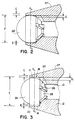
- Figs. 2 and 3 pen tips of the prior art and according to one embodiment of the invention, respectively, are shown before the spinning procedure.
- the outer cone surface 27 Prior to spinning, the outer cone surface 27 is tapered at a 25 to 40 degree angle, with thirty degrees being preferred in the instant invention, and the initial rim structure 22 has initial rim thickness C.
- socket 18 has an initial diameter (F 1 , see also Fig. 6) greater than that of ball 24 by at least three percent.
- F 1 is at learnt 1.03 millimeter, preferably about 1.06 millimeter.
- the initial socket diameter can be somewhat larger, e.g., up to about ten percent of the ball diameter, if so desired.
- the relatively large initial diameter of the socket substantially increases the portions of channels 26 which extend beyond the surface of ball 24 in contact with the seat (D 1 ), preventing channel blockage when ball 24 wears into the seat and wears down lands 28 during extended use and providing a larger area in the finished pen (see region 17, Fig. 8), thus increasing the area to which excess ink can be returned during writing and improving ink coverage of the surface of ball 24.
- Preferred ink laydown rates are from about 12 to 18 mg/185 ft., for the embodiment disclosed. It should be well understood that other ink laydown rates may be obtained for other ball/rim structure combinations, by the practice of the present invention.
- the initial thickness of initial rim structure 22 can either be reduced or increased by facing the initial rim structure 22 to a lesser or greater degree before the ball is inserted in the socket.
- the initial rim structure 22 can be faced a predetermined amount (determined by trying different initial rim thicknesses to establish what thickness provides the desired ink laydown) to obtain a suitable initial rim thickness.
- FIG. 5 A conventional facing tool 30 is shown in Figs. 5 and 5a, with arrow 31 indicating the rotation of the cutting edge 33 as the tool 30 moves downward to remove material from the surface of the initial rim structure.
- Fig. 6 shows material 29 which may be removed by facing, causing the initial thickness of rim structure 22 to increase from T 1 to T 2 . Facing is typically performed at about 14,000 to 17,000 rpm for stainless steel tubular members, and up to about 22,000 rpm for brass tubular members.
- Fig. 7 shows a conventional spinning head 34, which includes rollers 36 and 38.
- a typical spinning head may be obtained from Mikron, Lugano, Switzerland.
- the entire spinning head 34 is driven in rotation in the direction indicated by the large arrow (B), while rollers 36 and 38 are freewheeling and rotate in the opposite direction upon contacting the pen tip, as indicated by the smaller arrows (A).
- Spinning head faces 40 and 42 are inclined to provide the desired spin angle, preferably about sixty degrees, as described above.
- the amount of elongation which the metal of rim 22 experiences, and thus the thinning of the rim which occurs, depends upon the speed of revolution of the spinning head 34 and force applied to the spinning head.
- the thickness of finished rim structure 22' can be easily maintained more or less constant, regardless of the initial rim thickness used.
- Typical spinning pressures and spinning speeds are well known to those skilled in the art.
- Fig. 8 shows an enlarged, detailed view of the finished pen tip.
- the inner diameter F 1 of the socket at the intersection of seat 20 and cylindrical wall 11 (intersection 19) has not been changed by the spinning operation, and remains significantly larger than the diameter of ball 24.
- Finished rim structure 22' has finished rim thickness C 3 of approximately 0.025 millimeter.
Landscapes
- Engineering & Computer Science (AREA)
- Mechanical Engineering (AREA)
- Pens And Brushes (AREA)
- Coating Apparatus (AREA)
Claims (10)
- Procédé d'obtention d'une valeur de débit d'encre d'un crayon à bille, le procédé comprenant la disposition d'un premier organe tubulaire ayant une partie intérieure qui peut être mise en communication avec une réserve d'encre qui circule, le premier organe tubulaire ayant un logement muni d'un siège formé à une première extrémité du premier organe tubulaire, une surface de paroi interne s'étendant depuis le siège et un rebord annulaire disposé à l'extrémité de la surface de paroi interne opposée au siège, le rebord ayant une première épaisseur initiale, l'insertion d'une bille dans le logement, la réduction des dimensions circonférentielles du rebord annulaire afin que la bille soit retenue dans le logement, et la mesure d'un premier débit d'encre, le procédé étant caractérisé par les étapes suivantes : la réduction de la première épaisseur initiale du rebord à une première épaisseur finale au cours de la réduction des dimensions circonférentielles, la disposition d'un second organe tubulaire ayant une partie intérieure qui peut être mise en communication avec une réserve d'encre qui circule, le second organe tubulaire ayant un logement muni d'un siège formé à une première extrémité du second organe tubulaire, les diamètres du logement des premier et second organes tubulaires étant les mêmes, une surface de paroi interne s'étendant depuis le siège et un rebord annulaire ayant une seconde épaisseur initiale étant placé à l'extrémité de la surface de paroi interne opposée au siège, l'insertion, dans le logement du second organe tubulaire, d'une seconde bille ayant un diamètre égal à celui de la bille introduite dans le premier organe tubulaire, la réduction du rebord du second organe tubulaire à une seconde épaisseur finale qui diffère de la première épaisseur finale avec réduction des dimensions circonférentielles du rebord annulaire du second organe tubulaire afin que la bille soit retenue dans le logement et donne un espace d'écoulement entre le bord périphérique interne du rebord du second organe tubulaire et la surface de la seconde bille, cet espace d'écoulement donnant un second dépôt d'encre différent du premier dépôt d'encre.
- Procédé selon la revendication 1, caractérisé en ce que la variation de l'épaisseur du rebord du second organe tubulaire comprend l'usinage de la surface du rebord du second organe tubulaire.
- Procédé selon la revendication 1, caractérisé en ce que la surface de paroi interne du premier organe tubulaire est une paroi cylindrique, en ce que la surface de paroi interne du second organe tubulaire est une paroi cylindrique, en ce que la variation de l'épaisseur du rebord du second organe tubulaire comprend l'usinage de la surface du rebord pour qu'une partie de la paroi cylindrique du second organe tubulaire soit retirée, en ce que la bille est retenue dans le logement du second organe tubulaire par réduction des dimensions circonférentielles du rebord respectif, et en ce que le second dépôt d'encre est mesuré.
- Procédé selon l'une quelconque des revendications 1 à 3, caractérisé en ce que le diamètre de la bille est inférieur d'au moins 3 % au diamètre du siège à l'intersection du siège et de la surface de paroi interne.
- Procédé selon l'une quelconque des revendications 1 à 4, caractérisé en ce que le siège comprend un orifice central, un ensemble de canaux de distribution s'étendant radialement depuis l'orifice et destinés à transmettre l'encre à la surface de la bille, et des portées placées entre les canaux de distribution et destinées à être au contact de la surface de la bille.
- Procédé selon la revendication 5, caractérisé en ce que les canaux de distribution s'étendent vers la surface de paroi interne du logement.
- Procédé selon l'une quelconque des revendications 1 à 6, caractérisé en ce que le diamètre de la bille est inférieur de 0,05 à 0,08 mm environ au diamètre du siège à l'intersection du siège et de la surface de paroi interne.
- Procédé selon l'une quelconque des revendications 1 à 7, caractérisé en ce que, initialement, l'épaisseur du rebord est comprise entre environ 0,03 et 0,08 mm.
- Procédé d'obtention d'une valeur de débit d'encre d'un crayon à bille, le procédé comprenant la disposition d'un organe tubulaire ayant une partie intérieure destinée à être placée en communication avec une réserve d'encre pour la circulation de celle-ci, un logement ayant un siège formé à une première extrémité de l'organe tubulaire, une surface de paroi interne s'étendant depuis le siège, et un rebord annulaire disposé à l'extrémité de la surface de paroi interne opposée au siège et ayant une première épaisseur, et l'insertion d'une bille dans le logement, le procédé étant caractérisé par la réduction de la première épaisseur du rebord à une seconde épaisseur avant l'étape d'insertion de la bille dans le logement, et la réduction des dimensions circonférentielles du rebord pour que la bille soit retenue dans le logement avec réduction de la seconde épaisseur du rebord pour la formation d'un espace de circulation entre le bord périphérique interne du rebord et la surface de la bille, cet espace de circulation déterminant le débit d'encre.
- Procédé selon la revendication 9, caractérisé en ce que l'épaisseur du rebord varie d'une première épaisseur à une seconde épaisseur par usinage de la surface du rebord qui retire une partie de ce rebord.
Applications Claiming Priority (3)
| Application Number | Priority Date | Filing Date | Title |
|---|---|---|---|
| US90494792A | 1992-06-26 | 1992-06-26 | |
| PCT/US1993/005925 WO1994000304A1 (fr) | 1992-06-26 | 1993-06-21 | Stylo a bille |
| US904947 | 2001-07-13 |
Publications (3)
| Publication Number | Publication Date |
|---|---|
| EP0725736A4 EP0725736A4 (fr) | 1995-07-13 |
| EP0725736A1 EP0725736A1 (fr) | 1996-08-14 |
| EP0725736B1 true EP0725736B1 (fr) | 2000-08-30 |
Family
ID=25420022
Family Applications (1)
| Application Number | Title | Priority Date | Filing Date |
|---|---|---|---|
| EP93916659A Expired - Lifetime EP0725736B1 (fr) | 1992-06-26 | 1993-06-21 | Stylo a bille |
Country Status (6)
| Country | Link |
|---|---|
| US (1) | US5520473A (fr) |
| EP (1) | EP0725736B1 (fr) |
| BR (1) | BR9306604A (fr) |
| DE (1) | DE69329348T2 (fr) |
| ES (1) | ES2149820T3 (fr) |
| WO (1) | WO1994000304A1 (fr) |
Families Citing this family (25)
| Publication number | Priority date | Publication date | Assignee | Title |
|---|---|---|---|---|
| CA2147916C (fr) * | 1994-04-29 | 2005-03-22 | Masashi Ando | Pointe de stylo-bille, methode de fabrication et stylo utilisant une telle pointe |
| KR100393163B1 (ko) * | 1994-08-10 | 2003-10-22 | 펜텔 가부시기가이샤 | 볼펜칩과그제조방법 |
| JP3492438B2 (ja) * | 1995-02-07 | 2004-02-03 | 三菱鉛筆株式会社 | ボールペン用金属チップ |
| JP3434975B2 (ja) * | 1996-06-03 | 2003-08-11 | 三菱鉛筆株式会社 | ボールペン |
| KR100342753B1 (ko) * | 1997-01-07 | 2002-07-04 | 미츠비시엔피츠가부시키가이샤 | 볼펜 |
| JPH10278474A (ja) * | 1997-04-03 | 1998-10-20 | Mitsubishi Pencil Co Ltd | ボールペンのペン先 |
| EP1038693B1 (fr) * | 1999-03-26 | 2011-07-13 | Sakura Color Products Corporation | Pointe de stylo et applicateur muni de cette pointe |
| US7197174B1 (en) | 1999-09-15 | 2007-03-27 | Intel Corporation | Magnetic ink encoding pen |
| US6422776B1 (en) * | 1999-09-20 | 2002-07-23 | Sakura Color Products Corporation | Ball-point pen and a penpoint tip therein |
| US6224284B1 (en) | 1999-10-12 | 2001-05-01 | Dri Mark Products Incorporated | Metallic ink composition for wick type writing instruments |
| US7374644B2 (en) | 2000-02-17 | 2008-05-20 | Applied Materials, Inc. | Conductive polishing article for electrochemical mechanical polishing |
| JP2001310581A (ja) * | 2000-04-28 | 2001-11-06 | Pilot Ink Co Ltd | ボールペンチップ |
| WO2002055317A1 (fr) * | 2001-01-10 | 2002-07-18 | Mitsubishi Pencil Kabushikikaisha | Cartouche de stylo a bille |
| US20030072639A1 (en) * | 2001-10-17 | 2003-04-17 | Applied Materials, Inc. | Substrate support |
| EP1329337A1 (fr) * | 2002-01-17 | 2003-07-23 | Schächter, Friedrich | Outil pour la production des pointes de stylo à bille |
| JP4309104B2 (ja) * | 2002-08-14 | 2009-08-05 | 株式会社ツバキ・ナカシマ | ボールペン用ボール |
| TWI355333B (en) * | 2003-05-27 | 2012-01-01 | Sakura Color Prod Corp | Method for manufacturing a tip for an applicator |
| JP2009101551A (ja) | 2007-10-22 | 2009-05-14 | Zebra Pen Corp | ニードル型ボールペンチップ |
| JP5088897B2 (ja) * | 2009-03-10 | 2012-12-05 | 三菱鉛筆株式会社 | ボールペンチップ、ボールペンリフィル、ボールペン及びボールペンチップの製造方法 |
| CN103144463A (zh) * | 2013-03-29 | 2013-06-12 | 四川大学 | 一种可拆分中性笔笔头 |
| JP6351100B2 (ja) * | 2014-07-15 | 2018-07-04 | 株式会社サクラクレパス | ボールペン |
| CN104309359A (zh) * | 2014-10-22 | 2015-01-28 | 意瑞纳米科技(昆山)有限公司 | 一种针管笔头 |
| JP6804875B2 (ja) * | 2016-05-31 | 2020-12-23 | 三菱鉛筆株式会社 | ボールペン |
| TWI711770B (zh) * | 2019-02-27 | 2020-12-01 | 王鼎瑞 | 側向定位裝置 |
| TWI708016B (zh) * | 2019-03-15 | 2020-10-21 | 王鼎瑞 | 操控裝置的組合方法與結構 |
Family Cites Families (45)
| Publication number | Priority date | Publication date | Assignee | Title |
|---|---|---|---|---|
| FR965583A (fr) * | 1950-09-15 | |||
| CA734725A (en) * | 1966-05-24 | C. Shuman Robert | Ball point pen nib | |
| FR66051E (fr) * | 1956-05-03 | |||
| GB660784A (en) * | 1946-09-05 | 1951-11-14 | Eagle Pencil Co | Improvements in or relating to ball point writing instruments |
| FR935742A (fr) * | 1946-10-11 | 1948-06-29 | Stylographe perfectionné à bille traçante, procédé et machine pour son montage | |
| US2592406A (en) * | 1949-05-05 | 1952-04-08 | William G Faltin | Fountain pen of the ball point type |
| DE804295C (de) * | 1949-07-22 | 1951-04-19 | Walter Weigle | Kugelschreiber |
| GB713169A (en) * | 1949-12-06 | 1954-08-04 | Leeds & Northrup Co | A marker device of the ball point type for use in recording instruments |
| US2813512A (en) * | 1953-05-18 | 1957-11-19 | Paper Mate Mfg Co | Method of improving the life of ballpoint writing instruments |
| US2813513A (en) * | 1954-04-12 | 1957-11-19 | Paper Mate Mfg Co | Ball point pen cartridge |
| BE557296A (fr) * | 1956-05-07 | |||
| DE1239590B (de) * | 1958-03-28 | 1967-04-27 | Faber Castell A W | Kugelschreiber |
| NL99134C (fr) * | 1957-10-01 | |||
| US3000353A (en) * | 1958-03-28 | 1961-09-19 | Faber Castell A W | Ball point pens |
| FR1212583A (fr) * | 1959-01-31 | 1960-03-24 | Support de bille pour stylo à bille et stylo à bille équipé de ce support | |
| US3315347A (en) * | 1964-09-29 | 1967-04-25 | Schachter Friedrich | Manufacture of composite writing points for ball point pens |
| GB1078681A (en) * | 1964-03-17 | 1967-08-09 | Irc Ltd | Improvements in and relating to ball point writing instruments |
| FR1568912A (fr) * | 1967-03-30 | 1969-05-30 | ||
| US3496627A (en) * | 1967-05-17 | 1970-02-24 | Giuseppe Mazzier | Method of forming ball tips for ball point pens and ball tips formed thereby |
| FR1576412A (fr) * | 1968-04-08 | 1969-08-01 | ||
| US3966336A (en) * | 1974-05-20 | 1976-06-29 | The Gillette Company | Ball type marker construction which eliminates stick-slip phenomena |
| JPS5412410Y2 (fr) * | 1975-12-10 | 1979-05-31 | ||
| IT1086630B (it) * | 1976-03-19 | 1985-05-28 | Pentel Kk | Punta per penna a sfera e procedimento di produzione |
| GB1564742A (en) * | 1976-10-01 | 1980-04-10 | Sakura Color Prod Corp | Ball-point pen for a low viscosiy ink |
| US4116569A (en) * | 1977-02-14 | 1978-09-26 | The Gillette Company | Ball holder for a ball-point pen |
| CA1088463A (fr) * | 1977-09-21 | 1980-10-28 | Masashi Koizumi | Stylo a bille, a encre en solution aqueuse, alimente par capillarite |
| FR2404537A1 (fr) * | 1977-09-29 | 1979-04-27 | Pilot Ink Co Ltd | Stylo a bille |
| FR2412471A1 (fr) * | 1977-12-22 | 1979-07-20 | Oreal | Dispositif distributeur de produit liquide ou pateux |
| JPS54156730A (en) * | 1978-05-30 | 1979-12-11 | Pentel Kk | Ball point for balllpoint pen with waterrsoluble ink |
| US4221490A (en) * | 1978-11-30 | 1980-09-09 | The Gillette Company | Two ended retractable writing instrument |
| JPS5614082U (fr) * | 1979-07-14 | 1981-02-06 | ||
| GB2065565B (en) * | 1979-12-21 | 1983-07-20 | Pilot Ink Co Ltd | Ball-point pen tip and ball-point pen provided with same |
| GB2067475A (en) * | 1980-01-14 | 1981-07-30 | Waite & Son Ltd | Ball point pen tip |
| US4311403A (en) * | 1980-03-26 | 1982-01-19 | National Pen Corporation | Ball-point pen device |
| JPS58192084U (ja) * | 1982-06-16 | 1983-12-20 | シヤチハタ工業株式会社 | ボ−ルペン用ペン先体 |
| JPS59131678A (ja) * | 1983-01-18 | 1984-07-28 | Pilot Pen Co Ltd:The | 消去可能インキを使用したボ−ルペン |
| DE3301571A1 (de) * | 1983-01-19 | 1984-07-19 | Schmidt Feintechnik GmbH, 7742 St Georgen | Schreibspitze mit tintenleitsystem fuer tintenschreiber |
| DE3601676A1 (de) * | 1986-01-21 | 1987-07-23 | Rudi Hutt | Schreibspitze und verfahren zu ihrer herstellung |
| US4722124A (en) * | 1986-07-02 | 1988-02-02 | Mitsubishi Pencil Co., Ltd. | Method of manufacturing the writing tip of a ball point pen |
| DE3802746A1 (de) * | 1988-01-30 | 1989-08-03 | Schneider Geb Gmbh | Zeichengeraet mit einer zeichenspitze, deren stirnflaeche die gezeichnete strichstaerke bestimmt |
| DE3811530C1 (fr) * | 1988-04-06 | 1989-10-12 | Gebr. Schneider Gmbh, 7741 Tennenbronn, De | |
| DE3818786C1 (fr) * | 1988-06-02 | 1990-03-22 | J. S. Staedtler Gmbh & Co, 8500 Nuernberg, De | |
| JPH0261698A (ja) * | 1988-08-26 | 1990-03-01 | Fujitsu Ltd | 液晶表示装置の駆動方法 |
| US5012663A (en) * | 1990-03-28 | 1991-05-07 | Gillette Company | Method of bending a ball point pen tip |
| US5056949A (en) * | 1990-10-05 | 1991-10-15 | The Gillette Company | Correction fluid dispenser with ball valve |
-
1993
- 1993-06-21 BR BR9306604A patent/BR9306604A/pt not_active Application Discontinuation
- 1993-06-21 EP EP93916659A patent/EP0725736B1/fr not_active Expired - Lifetime
- 1993-06-21 ES ES93916659T patent/ES2149820T3/es not_active Expired - Lifetime
- 1993-06-21 WO PCT/US1993/005925 patent/WO1994000304A1/fr not_active Ceased
- 1993-06-21 DE DE69329348T patent/DE69329348T2/de not_active Expired - Fee Related
-
1995
- 1995-06-27 US US08/495,709 patent/US5520473A/en not_active Expired - Lifetime
Also Published As
| Publication number | Publication date |
|---|---|
| EP0725736A4 (fr) | 1995-07-13 |
| DE69329348D1 (de) | 2000-10-05 |
| US5520473A (en) | 1996-05-28 |
| BR9306604A (pt) | 1998-12-08 |
| EP0725736A1 (fr) | 1996-08-14 |
| ES2149820T3 (es) | 2000-11-16 |
| DE69329348T2 (de) | 2001-03-08 |
| WO1994000304A1 (fr) | 1994-01-06 |
Similar Documents
| Publication | Publication Date | Title |
|---|---|---|
| EP0725736B1 (fr) | Stylo a bille | |
| US7290965B2 (en) | Tool, method, and apparatus for removing burrs from bores | |
| US6647839B2 (en) | Method of forming an integral tubular projection in a work by spinning and a product produced by the same | |
| US5085014A (en) | Honing tool and method for the surface machining of bore walls | |
| KR0184722B1 (ko) | 유체베어링의 제조장치 | |
| EP1632359B1 (fr) | Procede de production d'une pointe d'applicateur | |
| US4842433A (en) | Pen tip structure | |
| EP0066541B1 (fr) | Méthode pour la production de pointe à bille pour stylo à encre aqueuse et pointe produite selon cette méthode | |
| US5188462A (en) | Lubricant system for a rotary cone rock bit | |
| JP2009101551A (ja) | ニードル型ボールペンチップ | |
| EP0389637B1 (fr) | Outil aleseur a electrodeposition | |
| JP3801862B2 (ja) | 流体通路を備えた工具ホルダ | |
| JP3035167B2 (ja) | 工具取付装置に用いられる工具抱持具 | |
| CA1086263A (fr) | Logement a surfaces connexes pour bille de stylo | |
| JP5549276B2 (ja) | ボールペンチップの製造方法 | |
| JP3070900B2 (ja) | 刃具径調整機構を備えた工具 | |
| US3302279A (en) | Method of making ballpoint-pen tips | |
| JP2010221408A (ja) | 塗布具 | |
| JP4688347B2 (ja) | 流体軸受スリーブの内径仕上げ加工工具およびそれを用いる加工装置 | |
| JP2000107947A (ja) | 円筒面加工装置、軸受内径加工装置及び円筒穴付構造体 | |
| JP2002254878A (ja) | ボールペンチップ及びその製造方法 | |
| JPS5864148A (ja) | スプレ−チツプ | |
| KR20010057361A (ko) | 필기구용 니들팁 및 그 제조방법 | |
| JP2000312943A (ja) | 円筒面を有する被加工物の製造方法及びその製造装置、並びに流体軸受の動圧溝の製造方法及びその製造装置 | |
| JP3472069B2 (ja) | 溝加工方法および溝加工装置 |
Legal Events
| Date | Code | Title | Description |
|---|---|---|---|
| A4 | Supplementary search report drawn up and despatched | ||
| AK | Designated contracting states |
Kind code of ref document: A4 Designated state(s): CH DE ES FR GB IT LI |
|
| PUAI | Public reference made under article 153(3) epc to a published international application that has entered the european phase |
Free format text: ORIGINAL CODE: 0009012 |
|
| 17P | Request for examination filed |
Effective date: 19950120 |
|
| AK | Designated contracting states |
Kind code of ref document: A1 Designated state(s): CH DE ES FR GB IT LI |
|
| 17Q | First examination report despatched |
Effective date: 19970221 |
|
| GRAG | Despatch of communication of intention to grant |
Free format text: ORIGINAL CODE: EPIDOS AGRA |
|
| GRAG | Despatch of communication of intention to grant |
Free format text: ORIGINAL CODE: EPIDOS AGRA |
|
| GRAH | Despatch of communication of intention to grant a patent |
Free format text: ORIGINAL CODE: EPIDOS IGRA |
|
| GRAH | Despatch of communication of intention to grant a patent |
Free format text: ORIGINAL CODE: EPIDOS IGRA |
|
| GRAA | (expected) grant |
Free format text: ORIGINAL CODE: 0009210 |
|
| AK | Designated contracting states |
Kind code of ref document: B1 Designated state(s): CH DE ES FR GB IT LI |
|
| REG | Reference to a national code |
Ref country code: CH Ref legal event code: EP |
|
| REG | Reference to a national code |
Ref country code: CH Ref legal event code: NV Representative=s name: A. BRAUN, BRAUN, HERITIER, ESCHMANN AG PATENTANWAE |
|
| REF | Corresponds to: |
Ref document number: 69329348 Country of ref document: DE Date of ref document: 20001005 |
|
| ITF | It: translation for a ep patent filed | ||
| REG | Reference to a national code |
Ref country code: ES Ref legal event code: FG2A Ref document number: 2149820 Country of ref document: ES Kind code of ref document: T3 |
|
| ET | Fr: translation filed | ||
| PG25 | Lapsed in a contracting state [announced via postgrant information from national office to epo] |
Ref country code: ES Free format text: LAPSE BECAUSE OF NON-PAYMENT OF DUE FEES Effective date: 20010622 |
|
| PLBE | No opposition filed within time limit |
Free format text: ORIGINAL CODE: 0009261 |
|
| STAA | Information on the status of an ep patent application or granted ep patent |
Free format text: STATUS: NO OPPOSITION FILED WITHIN TIME LIMIT |
|
| PG25 | Lapsed in a contracting state [announced via postgrant information from national office to epo] |
Ref country code: LI Free format text: LAPSE BECAUSE OF NON-PAYMENT OF DUE FEES Effective date: 20010630 Ref country code: CH Free format text: LAPSE BECAUSE OF NON-PAYMENT OF DUE FEES Effective date: 20010630 |
|
| 26N | No opposition filed | ||
| REG | Reference to a national code |
Ref country code: GB Ref legal event code: 732E |
|
| REG | Reference to a national code |
Ref country code: GB Ref legal event code: IF02 |
|
| REG | Reference to a national code |
Ref country code: CH Ref legal event code: PL |
|
| REG | Reference to a national code |
Ref country code: ES Ref legal event code: FD2A Effective date: 20020711 |
|
| PGFP | Annual fee paid to national office [announced via postgrant information from national office to epo] |
Ref country code: IT Payment date: 20080627 Year of fee payment: 16 |
|
| PGFP | Annual fee paid to national office [announced via postgrant information from national office to epo] |
Ref country code: GB Payment date: 20080627 Year of fee payment: 16 |
|
| PGFP | Annual fee paid to national office [announced via postgrant information from national office to epo] |
Ref country code: FR Payment date: 20090617 Year of fee payment: 17 |
|
| PGFP | Annual fee paid to national office [announced via postgrant information from national office to epo] |
Ref country code: DE Payment date: 20090629 Year of fee payment: 17 |
|
| GBPC | Gb: european patent ceased through non-payment of renewal fee |
Effective date: 20090621 |
|
| PG25 | Lapsed in a contracting state [announced via postgrant information from national office to epo] |
Ref country code: GB Free format text: LAPSE BECAUSE OF NON-PAYMENT OF DUE FEES Effective date: 20090621 |
|
| REG | Reference to a national code |
Ref country code: FR Ref legal event code: ST Effective date: 20110228 |
|
| PG25 | Lapsed in a contracting state [announced via postgrant information from national office to epo] |
Ref country code: IT Free format text: LAPSE BECAUSE OF NON-PAYMENT OF DUE FEES Effective date: 20090621 |
|
| PG25 | Lapsed in a contracting state [announced via postgrant information from national office to epo] |
Ref country code: DE Free format text: LAPSE BECAUSE OF NON-PAYMENT OF DUE FEES Effective date: 20110101 |
|
| PG25 | Lapsed in a contracting state [announced via postgrant information from national office to epo] |
Ref country code: FR Free format text: LAPSE BECAUSE OF NON-PAYMENT OF DUE FEES Effective date: 20100630 |