EP0725922B1 - Vorrichtung zur durchflussmessung - Google Patents
Vorrichtung zur durchflussmessung Download PDFInfo
- Publication number
- EP0725922B1 EP0725922B1 EP94928763A EP94928763A EP0725922B1 EP 0725922 B1 EP0725922 B1 EP 0725922B1 EP 94928763 A EP94928763 A EP 94928763A EP 94928763 A EP94928763 A EP 94928763A EP 0725922 B1 EP0725922 B1 EP 0725922B1
- Authority
- EP
- European Patent Office
- Prior art keywords
- reflector
- ultrasound
- flow
- flowmeter according
- transducer
- Prior art date
- Legal status (The legal status is an assumption and is not a legal conclusion. Google has not performed a legal analysis and makes no representation as to the accuracy of the status listed.)
- Expired - Lifetime
Links
- 238000005259 measurement Methods 0.000 title claims description 22
- 238000002604 ultrasonography Methods 0.000 claims abstract description 29
- 101710118890 Photosystem II reaction center protein Ycf12 Proteins 0.000 claims description 5
- 239000007788 liquid Substances 0.000 claims description 4
- 238000010276 construction Methods 0.000 claims description 3
- 230000035945 sensitivity Effects 0.000 description 12
- 239000010261 arctane Substances 0.000 description 5
- LYCAIKOWRPUZTN-UHFFFAOYSA-N Ethylene glycol Chemical compound OCCO LYCAIKOWRPUZTN-UHFFFAOYSA-N 0.000 description 4
- 239000012530 fluid Substances 0.000 description 4
- 238000000527 sonication Methods 0.000 description 4
- 238000012360 testing method Methods 0.000 description 3
- XLYOFNOQVPJJNP-UHFFFAOYSA-N water Substances O XLYOFNOQVPJJNP-UHFFFAOYSA-N 0.000 description 3
- 240000006829 Ficus sundaica Species 0.000 description 2
- 230000005540 biological transmission Effects 0.000 description 2
- 230000007423 decrease Effects 0.000 description 2
- 238000011156 evaluation Methods 0.000 description 2
- WGCNASOHLSPBMP-UHFFFAOYSA-N hydroxyacetaldehyde Natural products OCC=O WGCNASOHLSPBMP-UHFFFAOYSA-N 0.000 description 2
- 241001136792 Alle Species 0.000 description 1
- 229910001369 Brass Inorganic materials 0.000 description 1
- 238000013459 approach Methods 0.000 description 1
- 239000010951 brass Substances 0.000 description 1
- 238000001816 cooling Methods 0.000 description 1
- 230000001419 dependent effect Effects 0.000 description 1
- 238000011161 development Methods 0.000 description 1
- 230000018109 developmental process Effects 0.000 description 1
- 230000000694 effects Effects 0.000 description 1
- 239000007789 gas Substances 0.000 description 1
- 238000000265 homogenisation Methods 0.000 description 1
- 239000000463 material Substances 0.000 description 1
- 230000003071 parasitic effect Effects 0.000 description 1
- 238000004886 process control Methods 0.000 description 1
- 230000005855 radiation Effects 0.000 description 1
- 230000006798 recombination Effects 0.000 description 1
- 238000005215 recombination Methods 0.000 description 1
- 238000007430 reference method Methods 0.000 description 1
- 230000011218 segmentation Effects 0.000 description 1
- 239000000126 substance Substances 0.000 description 1
Images




Classifications
-
- G—PHYSICS
- G01—MEASURING; TESTING
- G01F—MEASURING VOLUME, VOLUME FLOW, MASS FLOW OR LIQUID LEVEL; METERING BY VOLUME
- G01F1/00—Measuring the volume flow or mass flow of fluid or fluent solid material wherein the fluid passes through a meter in a continuous flow
- G01F1/66—Measuring the volume flow or mass flow of fluid or fluent solid material wherein the fluid passes through a meter in a continuous flow by measuring frequency, phase shift or propagation time of electromagnetic or other waves, e.g. using ultrasonic flowmeters
- G01F1/662—Constructional details
Definitions
- the invention relates to a US flow meter according to the preamble of claim 1.
- the previously known ultrasonic transducers have an almost Gaussian sensitivity distribution.
- the maximum sensitivity of the ultrasound transducer lies in its center. It decreases sharply towards the edge.
- the sensitivity is strongly influenced by the properties of the pipe wall when irradiation is carried out through the pipe wall. If you now sonicate the moving medium with an ultrasound transducer in a flow channel, as is known from DE 40 10 148 A1, in order to determine the flow velocity from the sound propagation time or by means of the Doppler effect, especially in the case of laminar flow profiles, the flow in the middle of the flow channel the highest flow velocity occurring is rated more strongly than the lower flow velocity occurring at the edge of the flow channel. The result of this is that there is a separate measurement characteristic for each flow profile and for each fluid, which leads to a complex evaluation unit.
- An ultrasonic measuring system is known from document US 4 103 551 specified for different flow properties.
- the device is used for ultrasonic flow measurement in a round Pipe that has two ultrasonic transducers running along it communicate with each other along an acoustic path in the pipe.
- the acoustic path includes a chord that represents the pipe radius halved.
- a device is known from the prior art EP 0 268 314 A1 to determine the flow in a cylindrical Tube known.
- the flow measuring device has a first and a second pair of ultrasonic transducers, each one of the ultrasonic transducers slants an ultrasonic signal in the tube emits in which the signal at two points of the Measuring tube is reflected and obliquely to the corresponding receiving transducer reached.
- This device can cause interference can be compensated for by eddies occurring in the river.
- the invention has for its object a device create that has a higher measurement accuracy and their measurement signal only from the flow and no longer from the type of used fluids and the current flow profile depends.
- Figure 1 shows a laminar and a turbulent flow profile in the flow channel cross section and possible flow profiles in the flow channel in side view.
- Figure 2 shows a conventional US flow meter with sonication of the flow channel parallel to the side wall.
- FIG. 3 shows the error curve of the US flow meter Figure 2.
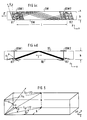
- Figure 4 shows an inventive US flow meter with spiral-shaped sonication of the flow channel.
- Figure 5 shows the dimensions of the flow channel for the determination the angle of reflection.
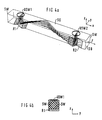
- Figure 6 shows a further embodiment of an inventive US flow meter.
- Figure 7 shows the error curve for the US flow meter Figure 4.
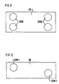
- Figure 8 shows a reflector of the US flow meter of Figure 4th
- Figure 9 shows the error curve for the US flow meter Figure 6.
- Figure 10 shows a reflector of the US flow meter of Figure 6.
- FIG. 11 and 12 show further exemplary embodiments according to the invention US flow meter with several US transmit and receive transducers or with axially offset US transceivers.
- the reflection angle be calculated.
- ⁇ for the ceiling and ground reflection, which in the embodiment shown gives the classic V-way of sound propagation, comes a new angle ⁇ for reflection on the side walls added (see Fig. 4c).
- the V-shaped sound path is characterized in that the Sound from converter USW1 via reflector R1 to the flow channel ceiling SD arrives, reflected from there towards R2 and is diverted from R2 to the ultrasonic transducer USW2 (a ceiling reflection, see. Fig. 4d).
- the Ultrasound emitted by a transmitter transducer over the stations -first reflector-flow channel ceiling-flow channel floor-flow channel ceiling-second Reflector to receive converter (three reflections on the walls of the flow channel).
- ⁇ v 0.5l arctane (
- ) 0.5l arctane (l ⁇ v /H)
- ⁇ w 0.5 l arctane (
- ) 0.5 l arctane (l ⁇ w /H)
- Both reflectors R1 and R2 and thus also the reflection surfaces RF1 and RF2 are rotated by the azimuth angle ⁇ (see FIG. 4c).
- the direction of rotation is irrelevant because symmetrical configurations arise.
- One reflector is rotated by the azimuth angle ⁇ , the other by the azimuth angle - ⁇ .
- the reflectors are each divided into two reflecting surfaces. Each of these reflection surfaces has its own alignment + ⁇ or - ⁇ , (see Figure 6c).
- the reflection surface RF11 of the first R1 is rotated by the angle - ⁇
- the reflection surface RF12 of the reflector R1 is rotated by the angle + ⁇ .
- the reflection surfaces RF21 and RF22 of the second reflector R2 are rotated in the same way.
- the determination of the azimuth angle ⁇ results, as in the case of exemplary embodiments 1 and 2, from the above equation.
- Such a combination of the reflectors splits the incident wavefront into two wavefronts which continue in different directions and which recombine in the second reflector R2 after having traveled through an equally long path.
- the azimuth angle ⁇ is chosen so that the first reflector R1 and the second reflector R2 result in a convex combination, ie the first reflection surface RF11 of the first reflector R1 is around the azimuth angle - ⁇ , the second reflection surface RF21 of the first reflector R1 is around the azimuth angle + ⁇ , the first reflection surface RF12 of the second reflector R2 is rotated by the azimuth angle + ⁇ and the second reflection surface RF22 of the second reflector R2 is rotated by the azimuth angle - ⁇ .
- the recombination of the wavefront in the second reflector R2 takes place here with redistribution of the sensitivity from the center to the edge and vice versa. Although this improves the distribution, signal level losses can be expected.
- the azimuth angle ⁇ is chosen such that the first reflector R1 and the second reflector R2 result in a concave combination, ie the first reflection surface RF11 of the first reflector R1 is by the azimuth angle + ⁇ , the second reflection surface RF21 of the first reflector R1 is by the Azimuth angle - ⁇ , the first reflection surface RF12 of the second reflector R2 is rotated by the azimuth angle + ⁇ and the second reflection surface RF22 of the second reflector R2 by the azimuth angle - ⁇ .
- the wave front is recombined here as in the fourth embodiment.
- the distance l ⁇ do not fall below the specified value range, otherwise the signal quality due to the high number of reflections would suffer.
- the embodiment 1 shown in Figure 4 with a V-shaped Sound path showed the best results in tests the linearity and the material independence of the characteristic (cf. see Figure 7).
- the error with the test medium glycol was in the tested measuring range from 100 - 4000 l / h at less than ⁇ 1.5 %.
- the measurement error was included with the sonication parallel to the side wall small rivers at> 18%. For water, the mistakes are in one Band of ⁇ 0.8% (previously 9%), each in comparison with one MID flow meter for which a maximum error of 0.5% can be accepted.
- the reflector shown in FIG. 8 can be used in particular in a flow meter according to FIG. 4.
- the reflector is preferably made of brass and has the dimensions given in the following table. This table also contains the dimensions of the flow channel.
- Sidewall angle of attack ⁇ 90
- the reflectors used in the flow meter according to FIG. 6 can be produced from the components shown in FIG. 10 as follows: From each pair of part B, the gray marked parts and once the white parts are cut as indicated in C and D. A part E and F are composed of one half each from C and D (two gray parts make up part E and two white parts make up part F). The dimensions and angles are given in Fig. 10 and Table 2.
- the measuring device is not only for Flow measurement suitable for various liquids, but also for the flow measurement of various gases and also for water flow meters, referred to as heat meters in heating-cooling systems.
Landscapes
- Physics & Mathematics (AREA)
- Electromagnetism (AREA)
- Fluid Mechanics (AREA)
- General Physics & Mathematics (AREA)
- Measuring Volume Flow (AREA)
- Investigating Or Analyzing Materials By The Use Of Ultrasonic Waves (AREA)
- Transducers For Ultrasonic Waves (AREA)
- Paper (AREA)
- Measuring Pulse, Heart Rate, Blood Pressure Or Blood Flow (AREA)
- Transition And Organic Metals Composition Catalysts For Addition Polymerization (AREA)
Description
Beschallt man nun mit einem Ultraschallwandler in einem Strömungskanal das bewegte Medium, wie dies aus der DE 40 10 148 A1 bekannt ist, um aus der Schallaufzeit oder mittels des Dopplereffekts die Strömungsgeschwindigkeit zu bestimmen, so wird, insbesondere bei laminarem Strömungsprofiffi, die in der Strömungskanalmitte auftretende höchste Strömungsgeschwindigkeit stärker bewertet als die am Rand des Strömungskanals auftretende niedrigere Strömungsgeschwindigkeit. Dies hat zur Folge, daß sich für jedes Strömungsprofil und für jedes Fluid eine eigene Meßkennlinie ergibt, was zu einer aufwendigen Auswerteeinheit führt.
| Länge | l = 130 mm |
| Hohe | h = 22 mm |
| Breite | b = 22 mm |
| Reflektor Radius | r = 14 mm |
| Reflektor Maß | bb = 3.11 mm |
| Reflektor Maß | x = 4.27 mm |
| Linker Drehwinkel | ΨL= -ArcTan[b/(0,5· l)]=-18.69° |
| Rechter Drehwinkel | ΨR = ΨL = -18.699° |
| V-Weg Vorgabe | lt1 = 0,5 · l |
| Gedrehter V-Weg | 1α = Abs[lt1/(Cos[ΨL])] |
| Boden-Decke Anstellwinkel | α= 0,5· l · ArcTan[lα/h] =36.11° |
| Seitenwände-Anstellwinkel | ϕ = 90 -2α = 17.77° |
| aa=r/(Cos[α]+Sin(α)/Tan[Pi/2-2 α]) x=aa Cos[α] bb=aa Sin[α] X bezeichnet die horizontale Projektion der Schrägfläche aa und bb die Höhe der Ränder. |
Aus je einem Paar des Teils B werden einmal die grau markierten Teile und einmal die weißen Teile wie in C und D angegeben passend geschnitten. Aus je einer Hälfte aus C und D werden ein Teil E bzw. F zusammengesetzt (zwei graue Teile ergeben einen Teil E und zwei weiße Teile ergeben ein Teil F). Die Bemaßung und die Winkel sind in Fig. 10 und Tabelle 2 angegeben.
| Länge | l = 130 mm |
| Höhe | h = 22 mm |
| Breite | b = 22 mm |
| Reflektor Radius | r = 14 mm |
| Reflektor Maß | bb = 3.11 mm |
| Reflektor Maß | x = 4.27 mm |
| 1.linker Drehwinkel | ΨL = -ArcTan[b/(0,5·l)]=-18.69° |
| 1.rechter Drehwinkel | ΨR = -ΨL =18.699° |
| 2.linker Drehwinkel | ΨL = -ΨL = 18.69° |
| 2.rechter Drehwinkel | ΨR = ΨL = -18.699° |
| V-Weg Vorgabe | lt1 = 0,5·1 |
| Gedrehter V-Weg | 1α = Abs[lt1/(Cos[ΨL])] |
| Boden-Decke Anstellwinkel | α = 0,5·l ArcTan[1α/h]=36.11° |
| Seitenwände-Anstellwinkel | ϕ = 90 - 2α = 17,77° |
- Alle Kombinationen der axialen und queraxialen Reflexionen
- Längenvariation
- Variation des Verhältnisses der Rohrabmessungen
- Kombination zweier oder mehrerer Meßrohre mit verschiedener Meßcharakteristik
- Verwendung von mehreren Sendern bei größeren Nennweiten
- sechseckiger Querschnitt
- ovaler oder runder Querschnitt
- Durchmesseränderung in axialer Richtung, konische Rohre
- Reflektoren auf verschiedenen Wänden
- gedrehte, ebene Reflektoren
- gedrehte und in mehrere Reflexionsflächen aufgeteilte Reflektoren
- gedrehte und/oder ungedrehte gekrümmte Reflektoren
- Sende- u. Empfangswandler auf einer Seite des Strömungskanals
- Sende- und Empfangswandler gegenüberliegend
- Sende- und Empfangswandler axial versetzt (s. Fig. 12)
- mehrere Sende- und Empfangswandler verteilt auf verschiedenen Seitenwänden (s. Fig. 11).
Claims (12)
- Durchflußmesser mit einem von einem gasförmigen oder flüssigen Medium durchströmenden Meßrohr, einem das Medium beschallenden Ultraschallwandler (USW1), einem im Meßrohr angeordneten ersten Reflektor (R1) und einem Ultraschall-Empfangswandler (USW2), wobei die einzelnen Komponenten derart zueinander orientiert sind, daß der Ultraschall zumindest eine Reflexion an einer ebenen Wandung des Meßrohrs erfährt, und wobei eine Flächennormale des ersten Reflektors (R1) drei von Null verschiedene Komponenten in einem rechtwinkligen Koordinatensystem aufweist, dessen eine Achse parallel zur Strömungsrichtung (F) orientiert ist.
- Durchflußmesser nach Anspruch 1,
gekennzeichnet durch
einen segmentiert aufgebauten ersten Reflektor (R1), wobei die Flächennormalen der Reflektorsegmente (RF11, RF12) nicht parallel zueinander orientiert sind. - Durchflußmesser nach Anspruch 1 oder 2,
dadurch gekennzeichnet,
daß der erste Reflektor (R1) dem Ultraschallwandler (USW1) im Meßrohr gegenüberliegend angeordnet ist. - Durchflußmesser nach einem der Ansprüche 1 bis 3,
dadurch gekennzeichnet,
daß der US-Wandler (USW1) den Ultraschall senkrecht zur Strömungsrichtung in das Meßrohr einstrahlt. - Durchflußmesser nach einem der Ansprüche 1 bis 4,
gekennzeichnet durch
einen im Meßrohr angeordneten zweiten Reflektor (R2). - Durchflußmesser nach Anspruch 5,
dadurch gekennzeichnet,
daß eine Flächennormale des zweiten Reflektors (R2) drei Komponenten in dem rechtwinkligen Koordinatensystem aufweist. - Durchflußmesser nach Anspruch 5 oder 6,
gekennzeichnet durch
einen segmentiert aufgebauten zweiten Reflektor (R2) wobei die Flächennormalen der Reflektorsegmente (RF21, RF22) nicht parallel zueinander orientiert sind. - Durchflußmesser nach einem der Ansprüche 5 bis 7,
dadurch gekennzeichnet,
daß der zweite Reflektor (R2) dem US-Empfangswandler (USW2) im Meßrohr gegenüberliegend angeordnet ist. - Durchflußmesser nach einem der Ansprüche 1 bis 8,
gekennzeichnet durch
einen ebenen ersten und/oder zweiten Reflektor (R1, R2). - Durchflußmesser nach einem der Ansprüche 1 bis 9,
dadurch gekennzeichnet,
daß die Reflektorsegmente (RF11, RF12, RF21, RF22) des ersten und/oder zweiten Reflektors (R1, R2) ebene Flächen sind. - Durchflußmesser nach einem der Ansprüche 1 bis 10,
dadurch gekennzeichnet,
daß eine Symmetrieachse des US-Wandlers (USW1) parallel zu einer Symmetrieachse des US-Empfangswandlers (USW2) orientiert ist. - Durchflußmesser nach einem der Ansprüche 1 bis 10,
dadurch gekennzeichnet,
daß eine Symmetrieachse des US-Wandlers (USW1) gegenüber einer Symmetrieachse des US-Empfangswandlers (USW2) geneigt ist.
Applications Claiming Priority (3)
| Application Number | Priority Date | Filing Date | Title |
|---|---|---|---|
| DE4336370A DE4336370C1 (de) | 1993-10-25 | 1993-10-25 | Vorrichtung zur Durchflußmessung |
| DE4336370 | 1993-10-25 | ||
| PCT/DE1994/001190 WO1995012110A1 (de) | 1993-10-25 | 1994-10-11 | Vorrichtung zur durchflussmessung |
Publications (2)
| Publication Number | Publication Date |
|---|---|
| EP0725922A1 EP0725922A1 (de) | 1996-08-14 |
| EP0725922B1 true EP0725922B1 (de) | 1998-07-15 |
Family
ID=6500965
Family Applications (1)
| Application Number | Title | Priority Date | Filing Date |
|---|---|---|---|
| EP94928763A Expired - Lifetime EP0725922B1 (de) | 1993-10-25 | 1994-10-11 | Vorrichtung zur durchflussmessung |
Country Status (9)
| Country | Link |
|---|---|
| US (1) | US5650572A (de) |
| EP (1) | EP0725922B1 (de) |
| JP (1) | JPH09504110A (de) |
| CN (1) | CN1079945C (de) |
| AT (1) | ATE168466T1 (de) |
| DE (2) | DE4336370C1 (de) |
| DK (1) | DK0725922T3 (de) |
| ES (1) | ES2119227T3 (de) |
| WO (1) | WO1995012110A1 (de) |
Families Citing this family (61)
| Publication number | Priority date | Publication date | Assignee | Title |
|---|---|---|---|---|
| DE4437588A1 (de) * | 1994-10-20 | 1996-04-25 | Siemens Ag | Ultraschall-Durchflußmeßgerät |
| DK0715155T3 (da) * | 1994-12-02 | 2001-08-13 | Siemens Ag | Ultralyd-flowmåleindretning |
| US5969263A (en) * | 1995-04-08 | 1999-10-19 | Schlumberger Industries, S.A. | Ultrasonic fluid counter for attenuating parasitic ultrasonic waves |
| DE19542232A1 (de) | 1995-11-13 | 1997-05-15 | Siemens Ag | Ultraschalldurchflußmesser für flüssige oder gasförmige Medien |
| FR2748816B1 (fr) * | 1996-05-17 | 1998-07-31 | Schlumberger Ind Sa | Dispositif ultrasonore de mesure de la vitesse d'ecoulement d'un fluide |
| DE19727960C2 (de) * | 1997-07-01 | 1999-10-14 | Peus Systems Gmbh | Vorrichtung zur zeitlich hochauflösenden Messung eines gasförmigen Volumenstromes, insbesondere eines Abgas-Volumenstromes eines Verbrennungsmotors, in einem von diesem durchströmten Rohr |
| DE19729473A1 (de) * | 1997-07-10 | 1999-02-04 | Meinecke Ag H | Ultraschall-Durchflußmesser |
| DE19743340C3 (de) * | 1997-09-30 | 2003-09-25 | Siemens Ag | Durchflußmesser |
| DE29719677U1 (de) * | 1997-11-05 | 1998-12-10 | Siemens AG, 80333 München | Durchflußmeßgerät |
| DE29719730U1 (de) * | 1997-11-06 | 1998-12-03 | Siemens AG, 80333 München | Durchflußmeßgerät |
| DE19755152C1 (de) * | 1997-12-11 | 1999-05-06 | Siemens Ag | Ultraschall-Durchflußmeßrohr |
| DE19808642C1 (de) * | 1998-02-28 | 1999-08-26 | Flexim Flexible Industriemeste | Vorrichtung zur Durchflußmessung |
| DE19861186B4 (de) * | 1998-03-02 | 2005-09-08 | Schubert & Salzer Control Systems Gmbh | Duchflussmessvorrichtung |
| DE19808701C2 (de) * | 1998-03-02 | 2000-01-20 | Georg F Wagner | Durchflussmessvorrichtung |
| DE29803911U1 (de) * | 1998-03-05 | 1999-04-01 | Siemens AG, 80333 München | Durchflußmesser |
| DE29803912U1 (de) * | 1998-03-05 | 1999-04-08 | Siemens AG, 80333 München | Durchflußmesser |
| US6098466A (en) * | 1998-06-09 | 2000-08-08 | Transonic Systems, Inc. | Ultrasonic flow sensor incorporating full flow illumination |
| IT1311771B1 (it) | 1999-02-24 | 2002-03-19 | Giorgio Bergamini | Misuratore perfezionato della portata di gas con gli ultrasuoni basato su specchi parabolici. |
| DE10034474C1 (de) * | 2000-07-15 | 2001-10-11 | Flexim Flexible Industriemeste | Verfahren und Vorrichtung zur Charakterisierung eines Fluides oder Gases mittels Ultraschall |
| JP2004520581A (ja) * | 2001-01-09 | 2004-07-08 | ランディス+ギュル・ゲゼルシャフト・ミット・ベシュレンクテル・ハフツング | 流量計 |
| DE20116591U1 (de) | 2001-10-10 | 2002-01-24 | Siemens AG, 80333 München | Einrichtung zur Erfassung der Position einer Leiterplatte |
| US6854339B2 (en) * | 2002-12-30 | 2005-02-15 | Pti Technologies, Inc. | Single-body dual-chip orthogonal sensing transit-time flow device using a parabolic reflecting surface |
| US6901812B2 (en) * | 2002-12-30 | 2005-06-07 | Pti Technologies, Inc. | Single-body dual-chip Orthogonal sensing transit-time flow device |
| US20040129088A1 (en) * | 2002-12-30 | 2004-07-08 | D.C. Tigwell & Associates | Single-body dual-chip orthogonal sensing transit-time flow device using a parabolic reflecting surface |
| JP4186645B2 (ja) * | 2003-02-24 | 2008-11-26 | 松下電器産業株式会社 | 超音波流量計測装置 |
| KR100694937B1 (ko) | 2003-02-24 | 2007-03-14 | 마츠시타 덴끼 산교 가부시키가이샤 | 초음파식 유체 계측 장치 |
| RU2264602C1 (ru) * | 2004-04-12 | 2005-11-20 | Деревягин Александр Михайлович | Ультразвуковой способ измерения расхода жидких и/или газообразных сред и устройство для его осуществления |
| DE102004053673A1 (de) * | 2004-11-03 | 2006-05-04 | Endress + Hauser Flowtec Ag | Vorrichtung zur Bestimmung und/oder Überwachung des Volumen- und/oder Massendurchflusses eines Mediums |
| DE102005063314B4 (de) * | 2005-02-17 | 2010-07-08 | Hydrometer Gmbh | Durchflussmesser |
| US7152490B1 (en) | 2005-08-15 | 2006-12-26 | Daniel Measurement And Control, Inc. | Methods for determining transducer delay time and transducer separation in ultrasonic flow meters |
| DE102005040238A1 (de) * | 2005-08-24 | 2007-03-01 | Endress + Hauser Flowtec Ag | Vorrichtung zur Bestimmung und/oder Überwachung einer Prozessgröße |
| DE202006021163U1 (de) | 2006-07-03 | 2013-08-01 | Endress + Hauser Flowtec Ag | Vorrichtung zur Bestimmung der Konzentrationen von Komponenten eines Gasgemisches |
| DE102006030964A1 (de) | 2006-07-03 | 2008-01-10 | Endress + Hauser Flowtec Ag | Vorrichtung und Verfahren zur Bestimmung der Konzentrationen von Komponenten eines Gasgemisches |
| US8348879B2 (en) * | 2006-08-28 | 2013-01-08 | Novartis Ag | Surgical system having a cassette with an acoustic air reflector |
| DE102007004936B4 (de) * | 2006-12-19 | 2011-01-13 | Krohne Ag | Ultraschalldurchflußmeßgerät |
| DE102008029772A1 (de) * | 2008-06-25 | 2009-12-31 | Endress + Hauser Flowtec Ag | Verfahren und Messsystem zur Bestimmung und/oder Überwachung des Durchflusses eines Messmediums durch ein Messrohr |
| EP2145696A1 (de) | 2008-07-15 | 2010-01-20 | UAB Minatech | Kapazitiver mikrogefertigter Ultraschallwandler und Verfahren zu seiner Herstellung |
| EP2154491A1 (de) | 2008-08-07 | 2010-02-17 | UAB Minatech | Ultraschallflussmesser, Wandlerbaugruppe und entsprechendes Verfahren |
| US7845240B1 (en) * | 2009-07-24 | 2010-12-07 | Elster NV/SA | Device and method for determining a flow characteristic of a fluid in a conduit |
| DE102009045620A1 (de) | 2009-10-13 | 2011-05-19 | Robert Bosch Gmbh | Ultraschallströmungssensor zur Erfassung einer Strömung eines fluiden Mediums |
| US8181536B2 (en) * | 2009-12-19 | 2012-05-22 | Cameron International Corporation | Ultrasonic Flow Meter including a transducer having conical face |
| CN101907472A (zh) * | 2010-07-05 | 2010-12-08 | 李俊国 | 一种超声波流量测量装置 |
| DE102011076000A1 (de) | 2011-05-17 | 2012-11-22 | Endress + Hauser Flowtec Ag | Ultraschall-Durchflussmessgerät |
| DE102011075997A1 (de) | 2011-05-17 | 2012-11-22 | Endress + Hauser Flowtec Ag | Ultraschall-Durchflussmessgerät |
| DE102011079250A1 (de) * | 2011-07-15 | 2013-01-17 | Endress + Hauser Flowtec Ag | Ultraschall-Durchflussmessgerät |
| CN102322980B (zh) * | 2011-09-02 | 2013-05-22 | 山东二十度节能技术服务有限公司 | 超声波热量表表体及其三维反射面位置参数的确定方法 |
| DE102012205640B4 (de) * | 2012-01-05 | 2018-05-30 | Continental Automotive Gmbh | Füllstandsgeber |
| DE102012101098A1 (de) * | 2012-02-10 | 2013-08-14 | Endress + Hauser Flowtec Ag | Ultraschall-Durchflussmessgerät und Verfahren zur Ermittlung der Fließgeschwindigkeit bzw. des Volumendurchflusses eines Fluids |
| DE102012013916A1 (de) | 2012-07-16 | 2014-01-16 | Endress + Hauser Flowtec Ag | Ultraschall-Durchflussmessgerät |
| DE102012109234A1 (de) | 2012-09-28 | 2014-04-03 | Endress + Hauser Flowtec Ag | Durchflussmessgerät, sowie Verwendung dieses Durchflussgerätes und Verfahren zur Ermittlung der Fließgeschwindigkeit |
| DE102012109237A1 (de) | 2012-09-28 | 2014-04-03 | Endress + Hauser Flowtec Ag | Durchflussmessgerät, sowie Verwendung dieses Durchflussgerätes und Verfahren zur Ermittlung der Fließgeschwindigkeit |
| DE102013105407A1 (de) | 2013-05-27 | 2014-11-27 | Endress + Hauser Flowtec Ag | Vorrichtung zur Bestimmung und/oder Überwachung des Volumen- und/oder Massedurchflusses eines Mediums |
| DE102013105922A1 (de) * | 2013-06-07 | 2014-12-11 | Endress + Hauser Flowtec Ag | Ultraschall-Durchflussmessgerät |
| US10048108B2 (en) * | 2013-07-26 | 2018-08-14 | Zhejiang Joy Electronic Technology Co., Ltd. | Ultrasonic flow meter having an entrance of a sound channel equipped with a chamfer for a smooth and restraint turbulent flow |
| DE102014001165A1 (de) | 2013-12-19 | 2015-06-25 | Endress + Hauser Flowtec Ag | Vorrichtung und Verfahren zur Bestimmung der Konzentrationen von Komponenten eines Gasgemisches |
| US9304024B2 (en) | 2014-01-13 | 2016-04-05 | Cameron International Corporation | Acoustic flow measurement device including a plurality of chordal planes each having a plurality of axial velocity measurements using transducer pairs |
| GB201411701D0 (en) * | 2014-07-01 | 2014-08-13 | Pcme Ltd | Methods and apparatus relating to ultrasound flow probes |
| EP3273205B1 (de) | 2016-07-18 | 2019-11-20 | Flexim Flexible Industriemesstechnik Gmbh | Verfahren und anordnung zur ultraschall-clamp-on-durchflussmessung und körper zur realisierung der messung |
| DE102017004038B4 (de) * | 2017-02-03 | 2022-01-27 | Diehl Metering Gmbh | Ultraschallzähler und Verfahren zur Erfassung einer Durchflussgröße |
| TWI615581B (zh) * | 2017-07-14 | 2018-02-21 | 達運精密工業股份有限公司 | 光反射罩及具有光反射罩的照明裝置 |
| CN120740690B (zh) * | 2025-08-12 | 2026-01-27 | 内蒙古农业大学 | 融合超声波时差且可扩展于浅窄河道的测流装置及方法 |
Family Cites Families (5)
| Publication number | Priority date | Publication date | Assignee | Title |
|---|---|---|---|---|
| US4103551A (en) * | 1977-01-31 | 1978-08-01 | Panametrics, Inc. | Ultrasonic measuring system for differing flow conditions |
| DE3539948A1 (de) * | 1985-11-11 | 1987-05-14 | Siemens Ag | Ultraschall-durchflussmesseinrichtung |
| NL8602690A (nl) * | 1986-10-27 | 1988-05-16 | Servex Bv | Inrichting voor het bepalen van de stromingssnelheid van een medium in een cylindrische leiding. |
| DE3861998D1 (de) * | 1987-08-10 | 1991-04-18 | Siemens Ag | Ultraschall-durchflussmesseinrichtung. |
| DE4010148A1 (de) * | 1990-03-29 | 1991-10-02 | Siemens Ag | Verbesserung fuer einen ultraschall-gas-/fluessigkeits-durchflussmesser |
-
1993
- 1993-10-25 DE DE4336370A patent/DE4336370C1/de not_active Expired - Fee Related
-
1994
- 1994-10-11 ES ES94928763T patent/ES2119227T3/es not_active Expired - Lifetime
- 1994-10-11 US US08/635,934 patent/US5650572A/en not_active Expired - Lifetime
- 1994-10-11 WO PCT/DE1994/001190 patent/WO1995012110A1/de not_active Ceased
- 1994-10-11 DE DE59406459T patent/DE59406459D1/de not_active Expired - Lifetime
- 1994-10-11 CN CN94194398A patent/CN1079945C/zh not_active Expired - Fee Related
- 1994-10-11 JP JP7512340A patent/JPH09504110A/ja active Pending
- 1994-10-11 DK DK94928763T patent/DK0725922T3/da active
- 1994-10-11 AT AT94928763T patent/ATE168466T1/de active
- 1994-10-11 EP EP94928763A patent/EP0725922B1/de not_active Expired - Lifetime
Also Published As
| Publication number | Publication date |
|---|---|
| DK0725922T3 (da) | 1999-04-19 |
| JPH09504110A (ja) | 1997-04-22 |
| EP0725922A1 (de) | 1996-08-14 |
| DE59406459D1 (de) | 1998-08-20 |
| ATE168466T1 (de) | 1998-08-15 |
| US5650572A (en) | 1997-07-22 |
| WO1995012110A1 (de) | 1995-05-04 |
| CN1079945C (zh) | 2002-02-27 |
| DE4336370C1 (de) | 1995-02-02 |
| CN1136844A (zh) | 1996-11-27 |
| ES2119227T3 (es) | 1998-10-01 |
Similar Documents
| Publication | Publication Date | Title |
|---|---|---|
| EP0725922B1 (de) | Vorrichtung zur durchflussmessung | |
| EP0521855B1 (de) | Verbesserung für einen ultraschall-gas-/flüssigkeits-durchflussmesser | |
| EP1337810B1 (de) | Durchflussmesser | |
| EP2710336B1 (de) | Ultraschall-durchflussmessgerät | |
| EP0099024B1 (de) | Verfahren und Vorrichtungen zum Messen von Remissionen | |
| EP0099023B1 (de) | Remissionsmesskopf | |
| EP2710337B1 (de) | Ultraschall-durchflussmessgerät | |
| EP0715155B1 (de) | Ultraschall-Durchflussmessanordnung | |
| DE102014115203B3 (de) | Verfahren und Anordnung zur Ultraschall-Clamp-on-Durchflussmessung und Schaltungsanordnung zur Steuerung einer Ultraschall-Clamp-on-Durchflussmessung | |
| DE2732236B2 (de) | Vorrichtung zum Bestimmen der Durchflußmenge eines Fluids | |
| DE102015105685B3 (de) | Verfahren und Vorrichtung zum Erkennen des Vorhandenseins von Flüssigkeit in einem Gasstrom | |
| DE2552072A1 (de) | Einrichtung zur messung der stroemungsmittelstroemung in einer achssymmetrischen rohrleitung | |
| DE4336368C2 (de) | Vorrichtung zur Durchflußmessung | |
| EP3343185B1 (de) | Ultraschalldurchflussmessgerät und verfahren zur messung des durchflusses | |
| DE2122920C2 (de) | Verfahren zum Messen von Drehgeschwindigkeiten und Einrichtung zum Durchführen des Verfahrens | |
| EP0763717A2 (de) | Vorrichtung zur Ultraschall-Durchflussmessung | |
| EP0210263A1 (de) | Vorrichtung zur optischen ermittlung von gestaltsfehlern niedriger ordnung. | |
| DE3039710A1 (de) | Messwertgeber zur bestimmung der durchflussmenge einer stroemenden fluessigkeit | |
| DE19944047A1 (de) | Vorrichtung zur Messung der Konzentration oder Dichte sowie von Partikeln | |
| DE19503714A1 (de) | Anordnung zur Bestimmung der Strömungsgeschwindigkeit eines Fluides in Rohren mit kreisförmigem Querschnitt mittels Ultraschall | |
| DE2450439C3 (de) | Einrichtung zur berührungslosen Messung der Geschwindigkeit | |
| EP3748308A1 (de) | Ultraschalldurchflussmessgerät, verwendung eines ultraschalldurchflussmessgerätes in einem absperrorgan und absperrorgan | |
| EP0917645B1 (de) | Verfahren und vorrichtung zur ultraschall-durchflussmessung | |
| DE69123990T2 (de) | Gerät zur Messung der Grössenverteilung von beugenden/streuenden Teilchen | |
| EP0504304B1 (de) | Ultraschall-gas-/flüssigkeits-durchflussmesser |
Legal Events
| Date | Code | Title | Description |
|---|---|---|---|
| PUAI | Public reference made under article 153(3) epc to a published international application that has entered the european phase |
Free format text: ORIGINAL CODE: 0009012 |
|
| 17P | Request for examination filed |
Effective date: 19960404 |
|
| AK | Designated contracting states |
Kind code of ref document: A1 Designated state(s): AT BE CH DE DK ES FR GB IE IT LI MC NL SE |
|
| GRAG | Despatch of communication of intention to grant |
Free format text: ORIGINAL CODE: EPIDOS AGRA |
|
| GRAG | Despatch of communication of intention to grant |
Free format text: ORIGINAL CODE: EPIDOS AGRA |
|
| GRAH | Despatch of communication of intention to grant a patent |
Free format text: ORIGINAL CODE: EPIDOS IGRA |
|
| 17Q | First examination report despatched |
Effective date: 19971222 |
|
| GRAH | Despatch of communication of intention to grant a patent |
Free format text: ORIGINAL CODE: EPIDOS IGRA |
|
| GRAA | (expected) grant |
Free format text: ORIGINAL CODE: 0009210 |
|
| AK | Designated contracting states |
Kind code of ref document: B1 Designated state(s): AT BE CH DE DK ES FR GB IE IT LI MC NL SE |
|
| REF | Corresponds to: |
Ref document number: 168466 Country of ref document: AT Date of ref document: 19980815 Kind code of ref document: T |
|
| REG | Reference to a national code |
Ref country code: CH Ref legal event code: NV Representative=s name: SIEMENS SCHWEIZ AG Ref country code: CH Ref legal event code: EP |
|
| REF | Corresponds to: |
Ref document number: 59406459 Country of ref document: DE Date of ref document: 19980820 |
|
| REG | Reference to a national code |
Ref country code: ES Ref legal event code: FG2A Ref document number: 2119227 Country of ref document: ES Kind code of ref document: T3 |
|
| GBT | Gb: translation of ep patent filed (gb section 77(6)(a)/1977) |
Effective date: 19980915 |
|
| REG | Reference to a national code |
Ref country code: IE Ref legal event code: FG4D Free format text: GERMAN |
|
| ET | Fr: translation filed | ||
| REG | Reference to a national code |
Ref country code: DK Ref legal event code: T3 |
|
| PLBE | No opposition filed within time limit |
Free format text: ORIGINAL CODE: 0009261 |
|
| STAA | Information on the status of an ep patent application or granted ep patent |
Free format text: STATUS: NO OPPOSITION FILED WITHIN TIME LIMIT |
|
| 26N | No opposition filed | ||
| PGFP | Annual fee paid to national office [announced via postgrant information from national office to epo] |
Ref country code: MC Payment date: 20010919 Year of fee payment: 8 |
|
| PGFP | Annual fee paid to national office [announced via postgrant information from national office to epo] |
Ref country code: IE Payment date: 20010926 Year of fee payment: 8 |
|
| PGFP | Annual fee paid to national office [announced via postgrant information from national office to epo] |
Ref country code: SE Payment date: 20011018 Year of fee payment: 8 |
|
| PGFP | Annual fee paid to national office [announced via postgrant information from national office to epo] |
Ref country code: ES Payment date: 20011024 Year of fee payment: 8 Ref country code: BE Payment date: 20011024 Year of fee payment: 8 |
|
| REG | Reference to a national code |
Ref country code: GB Ref legal event code: IF02 |
|
| PG25 | Lapsed in a contracting state [announced via postgrant information from national office to epo] |
Ref country code: IE Free format text: LAPSE BECAUSE OF NON-PAYMENT OF DUE FEES Effective date: 20021011 |
|
| PG25 | Lapsed in a contracting state [announced via postgrant information from national office to epo] |
Ref country code: SE Free format text: LAPSE BECAUSE OF NON-PAYMENT OF DUE FEES Effective date: 20021012 Ref country code: ES Free format text: LAPSE BECAUSE OF NON-PAYMENT OF DUE FEES Effective date: 20021012 |
|
| PG25 | Lapsed in a contracting state [announced via postgrant information from national office to epo] |
Ref country code: BE Free format text: LAPSE BECAUSE OF NON-PAYMENT OF DUE FEES Effective date: 20021031 |
|
| BERE | Be: lapsed |
Owner name: *SIEMENS A.G. Effective date: 20021031 |
|
| PG25 | Lapsed in a contracting state [announced via postgrant information from national office to epo] |
Ref country code: MC Free format text: LAPSE BECAUSE OF NON-PAYMENT OF DUE FEES Effective date: 20030501 |
|
| EUG | Se: european patent has lapsed | ||
| REG | Reference to a national code |
Ref country code: IE Ref legal event code: MM4A |
|
| REG | Reference to a national code |
Ref country code: ES Ref legal event code: FD2A Effective date: 20031112 |
|
| PG25 | Lapsed in a contracting state [announced via postgrant information from national office to epo] |
Ref country code: IT Free format text: LAPSE BECAUSE OF NON-PAYMENT OF DUE FEES Effective date: 20051011 |
|
| NLS | Nl: assignments of ep-patents |
Owner name: LANDIS+GYR GMBH Effective date: 20061018 |
|
| REG | Reference to a national code |
Ref country code: CH Ref legal event code: PCAR Free format text: SIEMENS SCHWEIZ AG;INTELLECTUAL PROPERTY FREILAGERSTRASSE 40;8047 ZUERICH (CH) |
|
| PGFP | Annual fee paid to national office [announced via postgrant information from national office to epo] |
Ref country code: FR Payment date: 20121031 Year of fee payment: 19 |
|
| PGFP | Annual fee paid to national office [announced via postgrant information from national office to epo] |
Ref country code: GB Payment date: 20121011 Year of fee payment: 19 |
|
| PGFP | Annual fee paid to national office [announced via postgrant information from national office to epo] |
Ref country code: CH Payment date: 20130110 Year of fee payment: 19 Ref country code: DE Payment date: 20121216 Year of fee payment: 19 |
|
| PGFP | Annual fee paid to national office [announced via postgrant information from national office to epo] |
Ref country code: DK Payment date: 20131024 Year of fee payment: 20 |
|
| PGFP | Annual fee paid to national office [announced via postgrant information from national office to epo] |
Ref country code: AT Payment date: 20130918 Year of fee payment: 20 |
|
| PGFP | Annual fee paid to national office [announced via postgrant information from national office to epo] |
Ref country code: NL Payment date: 20131021 Year of fee payment: 20 |
|
| REG | Reference to a national code |
Ref country code: CH Ref legal event code: PL |
|
| GBPC | Gb: european patent ceased through non-payment of renewal fee |
Effective date: 20131011 |
|
| REG | Reference to a national code |
Ref country code: DE Ref legal event code: R119 Ref document number: 59406459 Country of ref document: DE Effective date: 20140501 |
|
| PG25 | Lapsed in a contracting state [announced via postgrant information from national office to epo] |
Ref country code: GB Free format text: LAPSE BECAUSE OF NON-PAYMENT OF DUE FEES Effective date: 20131011 Ref country code: LI Free format text: LAPSE BECAUSE OF NON-PAYMENT OF DUE FEES Effective date: 20131031 Ref country code: CH Free format text: LAPSE BECAUSE OF NON-PAYMENT OF DUE FEES Effective date: 20131031 |
|
| REG | Reference to a national code |
Ref country code: FR Ref legal event code: ST Effective date: 20140630 |
|
| PG25 | Lapsed in a contracting state [announced via postgrant information from national office to epo] |
Ref country code: DE Free format text: LAPSE BECAUSE OF NON-PAYMENT OF DUE FEES Effective date: 20140501 Ref country code: FR Free format text: LAPSE BECAUSE OF NON-PAYMENT OF DUE FEES Effective date: 20131031 |
|
| REG | Reference to a national code |
Ref country code: DK Ref legal event code: EUP Effective date: 20141011 |
|
| REG | Reference to a national code |
Ref country code: NL Ref legal event code: V4 Effective date: 20141011 |
|
| REG | Reference to a national code |
Ref country code: AT Ref legal event code: MK07 Ref document number: 168466 Country of ref document: AT Kind code of ref document: T Effective date: 20141011 |