EP0726174A1 - Luftreifen und Verfahren zu seiner Herstellung - Google Patents
Luftreifen und Verfahren zu seiner Herstellung Download PDFInfo
- Publication number
- EP0726174A1 EP0726174A1 EP96300887A EP96300887A EP0726174A1 EP 0726174 A1 EP0726174 A1 EP 0726174A1 EP 96300887 A EP96300887 A EP 96300887A EP 96300887 A EP96300887 A EP 96300887A EP 0726174 A1 EP0726174 A1 EP 0726174A1
- Authority
- EP
- European Patent Office
- Prior art keywords
- tyre
- mould
- split
- plates
- protrusions
- Prior art date
- Legal status (The legal status is an assumption and is not a legal conclusion. Google has not performed a legal analysis and makes no representation as to the accuracy of the status listed.)
- Granted
Links
- 238000004519 manufacturing process Methods 0.000 title claims abstract description 7
- 238000000465 moulding Methods 0.000 claims description 5
- 238000000034 method Methods 0.000 claims 1
- 239000011324 bead Substances 0.000 description 4
- 230000007423 decrease Effects 0.000 description 4
- 239000004677 Nylon Substances 0.000 description 2
- 229920000297 Rayon Polymers 0.000 description 2
- 239000004760 aramid Substances 0.000 description 2
- 229920003235 aromatic polyamide Polymers 0.000 description 2
- 239000000835 fiber Substances 0.000 description 2
- 229920001778 nylon Polymers 0.000 description 2
- 229920000728 polyester Polymers 0.000 description 2
- 239000002964 rayon Substances 0.000 description 2
- 229910000831 Steel Inorganic materials 0.000 description 1
- 230000000694 effects Effects 0.000 description 1
- 238000010438 heat treatment Methods 0.000 description 1
- 239000010959 steel Substances 0.000 description 1
Images


Classifications
-
- B—PERFORMING OPERATIONS; TRANSPORTING
- B29—WORKING OF PLASTICS; WORKING OF SUBSTANCES IN A PLASTIC STATE IN GENERAL
- B29D—PRODUCING PARTICULAR ARTICLES FROM PLASTICS OR FROM SUBSTANCES IN A PLASTIC STATE
- B29D30/00—Producing pneumatic or solid tyres or parts thereof
- B29D30/06—Pneumatic tyres or parts thereof (e.g. produced by casting, moulding, compression moulding, injection moulding, centrifugal casting)
- B29D30/0601—Vulcanising tyres; Vulcanising presses for tyres
- B29D30/0606—Vulcanising moulds not integral with vulcanising presses
- B29D30/0629—Vulcanising moulds not integral with vulcanising presses with radially movable sectors
-
- B—PERFORMING OPERATIONS; TRANSPORTING
- B29—WORKING OF PLASTICS; WORKING OF SUBSTANCES IN A PLASTIC STATE IN GENERAL
- B29C—SHAPING OR JOINING OF PLASTICS; SHAPING OF MATERIAL IN A PLASTIC STATE, NOT OTHERWISE PROVIDED FOR; AFTER-TREATMENT OF THE SHAPED PRODUCTS, e.g. REPAIRING
- B29C33/00—Moulds or cores; Details thereof or accessories therefor
- B29C33/0038—Moulds or cores; Details thereof or accessories therefor with sealing means or the like
-
- B—PERFORMING OPERATIONS; TRANSPORTING
- B60—VEHICLES IN GENERAL
- B60C—VEHICLE TYRES; TYRE INFLATION; TYRE CHANGING; CONNECTING VALVES TO INFLATABLE ELASTIC BODIES IN GENERAL; DEVICES OR ARRANGEMENTS RELATED TO TYRES
- B60C11/00—Tyre tread bands; Tread patterns; Anti-skid inserts
- B60C11/01—Shape of the shoulders between tread and sidewall, e.g. rounded, stepped or cantilevered
-
- B—PERFORMING OPERATIONS; TRANSPORTING
- B60—VEHICLES IN GENERAL
- B60C—VEHICLE TYRES; TYRE INFLATION; TYRE CHANGING; CONNECTING VALVES TO INFLATABLE ELASTIC BODIES IN GENERAL; DEVICES OR ARRANGEMENTS RELATED TO TYRES
- B60C13/00—Tyre sidewalls; Protecting, decorating, marking, or the like, thereof
- B60C13/02—Arrangement of grooves or ribs
Definitions
- the present invention relates to a pneumatic tyre and a method of making the same, in which the occurrence of burrs or spues of rubber caused in the buttress portion of the tyre along split lines of the vulcanising mould are prevented.
- pneumatic tyres particularly those having deep tread patterns for example snow tyres having a block type tread pattern and the like are manufactured by vulcanising a green tyre (raw tyre) in a split mould.
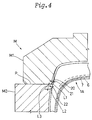
- such a mould (m) usually comprises sidewall dies (m2) (hereinafter called side-plates) disposed on both sides of a green tyre (t) and tread dies (m1) (hereinafter called sector plates) disposed around the tyre.
- each side-plate (m2) When vulcanising a green tyre (t), each side-plate (m2) is moved axially inwardly towards one of the tyre sidewalls and the sector plates (m1) are moved radially inwardly towards the tyre tread as shown in Fig.5 by arrows, and the split faces (p) of the sector plates (m1) and the side-plates (m2) contact with each other to close the space therebetween as shown in Fig.6.
- the dies (m1 and m2) collectively form a closed shell structure.
- a bladder or tube disposed inside the tyre in advance is inflated to a high pressure to thereby pressurise the inside of the tyre to press the tyre outer surface against the negative impression of the mould.
- burrs (a) are formed on the outer surface of the vulcanised tyre along the split lines of the mould.
- mould-split lines small lines corresponding to the split lines of a mould are more or less formed on the outer surface of a vulcanised tyre.
- the split lines of the mould is recognisable from such lines on the tyre outer surface (hereinafter mould-split lines).
- an object of the present invention to provide a pneumatic tyre and a method of making the same, in which the occurrence of burrs due to tyre rubber being trapped between the split faces of the vulcanising mould can be avoided.
- a pneumatic tyre comprises a tread portion and a pair of sidewall portions extending radially inwardly from tread edges, each sidewall portion having in a buttress region of the tyre a circumferentially extending mould-split line impressed by a split line of a split mould, wherein each sidewall portion is provided with a plurality of depressions and a circumferential groove, the depressions are formed radially outside the impressed mould-split line and arranged in a row along and adjacent to the impressed mould-split line, each depression having a depth of 0.5 to 5.0 mm and a maximum circumferential length of 5.0 to 10.0 mm, and the circumferential groove is formed radially inside the impressed mould-split line and extending along and adjacent to the impressed mould-split line, the circumferential groove having a depth of 1.0 to 3.0 mm and a width of from 2 to 10 mm.
- the total of the maximum circumferential lengths of the depressions is not less than 50 % of the circumferential length measured at the corresponding position.
- a method of making a tyre comprises steps of building a green tyre, putting the green tyre in the split mould, closing the split mould, and vulcanising the green tyre in the split mould, wherein the split mould comprises side-plates for moulding the axially outer surface of the tyre sidewall portions and sector plates for moulding the radially outer surface of the tyre tread portion, the side-plates being disposed oppositely each other in the axial direction of the tyre and being movable in the axial direction, the sector plates being disposed radially outside the sidewall plates and being movable in the radial direction of the tyre, such that in the closed state of the mould, the sector plates extend between radially outer edges of the side-plates to define split lines between the radially outer edges of the side-plates and radially inner edges of the sector plates, the inner surfaces of the sector plates being provided adjacent to the split lines with protrusions,
- the protrusions of the sector plates for forming the depressions and the ribs of the side-plates for forming the groove push back the green tyre from the split faces when closing the mould.
- the tyre raw rubber is prevented from being trapped between the split faces of the mould, and the occurrence of burrs can be effectively prevented.
- the pneumatic tyre 1 is a block pattern tyre.
- the tyre comprises a tread portion 2 with a tread surface 2A, a pair of axially spaced bead portions 4, a pair of sidewall portions 3 extending between the tread edges and the bead portions, a carcass 6 extending between the bead portions 4 through the tread portion 2 and sidewall portions 3 and turned up around bead cores 5, and a belt 7 disposed radially outside the carcass 6 and inside the tread portion 2.
- the carcass 6 comprises at least one ply, in this embodiment only one ply of cords arranged radially at an angle of from 90 to 75 degrees with respect to the tyre equator.
- organic fibre cords e.g. polyester, aromatic polyamide, nylon, rayon and the like are used.
- the belt 7 comprises two cross plies, each made of parallel cords laid at a small angle of not more than 5 degrees with respect to the tyre equator.
- steel cords or organic fibre cords e.g. aromatic polyamide, nylon, polyester, rayon and the like are used.
- the pneumatic tyre 1 is made by vulcanising and moulding a green tyre 1A in a split mould M.
- the split mould M comprises side-plates M2 and sector plates M1.
- each sidewall plate M2 has an annular shape and each sector plate M1 has a fan shape.
- the side-plates M2 are disposed oppositely each other so as to face the axially outer surface of the tyre sidewall portions 3.
- the sector plates M1 are disposed around the radially outside of the sidewall plates M2 so as to face the radially outer surface of the tyre tread portion 2.
- each sector plates M1 is provided with a negative impression of part of the block pattern.
- the split line between each of the side-plates and sector plates make a circle, and its corresponding position on the tyre is in the buttress region.
- the buttress region is the radially outer region of the sidewall portion which is immediately radially inside the tread edge and there buttresses 11 are provided.
- the sector plates M1 are supported to be movable in the radial direction and the side-plates M2 are supported to be movable in the axial direction. To close the mould M, the sector plates M1 are moved radially inwardly and the side-plates M2 are moved axially inwardly.
- the inner surface of the sector plate M1 is provided radially adjacent to the split face P with protrusions 20.
- the protrusions 20 are arranged circumferentially at a regular pitch, forming a space 21 therebetween.
- Each of the protrusions 20 extends radially outwardly from the edge of the split face P.
- the height of the protrusions 20 increase gradually from the edge of the split face P towards the radially outside thereof and also increases gradually from the position corresponding to the tread edge E towards the radially inside thereof.
- the maximum height L1 thereof is limited in the range of from 0.5 to 5.0 mm.
- the maximum circumferential length of the protrusions 20 is in the range of 5.0 to 10.0 mm, which occurs at the radially inner end thereof in this embodiment.
- the maximum circumferential lengths of the protrusions 20 amount to 50 to 90 % of the overall circumferential length measured at the corresponding position, that is, the radially inner end of the protrusions in this embodiment.
- the profile of the protrusions 20 is smoothly curved by an arc.
- the axially inner surface of the side-plate M2 is provided radially adjacent to the split face P with a rib 22.
- the rib 22 extends continuously in the circumferential direction.
- the maximum height L2 of the rib 22 is in the range of from 1.0 to 3.0 mm, and the width L3 is in the range of from 2 to 10 mm.
- the inside of the tyre is pressurised at a high pressure by means of inflation of a bladder 23 disposed therein, whereby the outer surface of the tyre is pressed onto the inner surface of the mould M.
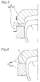
- the block pattern is impressed in the tread portion, and depressions 12 being negative of the protrusions 20 and a circumferential groove 13 being negative of the rib 22 are impressed in the buttress region of the vulcanised tyre as shown in Figs.2 and 3.
- the depressions 12 have a maximum depth D1 of 0.5 to 5.0 mm, and a maximum circumferential length LM of 5.0 to 10.0 mm.
- the maximum circumferential lengths LM of the depressions 12 amount to 50 to 90 % of the total length measured along the circumference passing at the maximum length position.
- the circumferential groove 13 has a depth D2 of from 1.0 to 3.0 mm and a width W of from 2 to 10 mm.
- buttress 11 are formed between the depressions 12 at a regular interval.
- mould-split line 9 corresponding to the split line or border line between the split faces P is impressed between the depressions 12 and the circumferential groove 13. But, no burr is formed.
- the mould-split line 9 is positioned radially outside the axial end of the belt 7 because deformation of the green tyre 1A during closing the mould is small in this region which is thus desirable for preventing the rubber from being bitten between the split faces.
- the depth of the depressions 12 of the tyre or the height of the protrusions 20 of the sector plates is less than 0.5 mm, it is difficult to push back the green tyre on the radially outside of the split line. Thus, burrs are liable to occur. If the depth or height is more than 5.0 mm, a stress concentration is liable to occur around the depressions. Thus, the durability of the tyre decreases.
- the maximum length of the depressions 12 or protrusions 20 is less than 5.0 mm, it is difficult to push back the green tyre on the radially outside of the split line. Thus, burrs are liable to occur. If the maximum length is more than 10.0 mm, the tyre strength decreases in the buttress region.
- the depth of the circumferential grooves 13 of the tyre or the height of the ribs 22 of the side-plates is less than 1.0 mm, as the amount of pushing-back is very small, burrs are liable to occur. If the depth or height is more than 3.0 mm, the profile of the tyre excessively changes at the grooves 13 and a stress concentration is liable to occur.
- the width of the circumferential grooves 13 or the ribs 22 is less than 2 mm, it is difficult to push back the green tyre by the side-plates, and burrs are liable to occur. If the width is more than 10 mm, the tyre strength decreases in the buttress region.
- the sector plates can not push back the green tyre the rubber on the radially outside of the split lines is bitten between the split faces and burrs occur.
- the total length is more preferably set in the range of not more than 90%, thereby effectively preventing the change in the tyre profile line, the concentration of stress and the decrease in the tyre strength.
- the above-mentioned height and depth are measured from the profile line of the tyre and mould normally thereto.
- the width and length are measured along the profile line.
- the effect of the protrusions is further enhanced.
- the maximum heights of the protrusions 20 and ribs 22, that is, the maximum depths of the depressions 12 and grooves 13 occur at a position within 10 mm from the split lines. As described above, according to the present invention, the occurrence of rubber burrs along the mould-split lines can be completely prevented.
Landscapes
- Engineering & Computer Science (AREA)
- Mechanical Engineering (AREA)
- Moulds For Moulding Plastics Or The Like (AREA)
- Heating, Cooling, Or Curing Plastics Or The Like In General (AREA)
- Tires In General (AREA)
- Tyre Moulding (AREA)
Applications Claiming Priority (3)
| Application Number | Priority Date | Filing Date | Title |
|---|---|---|---|
| JP49207/95 | 1995-02-13 | ||
| JP7049207A JP2955202B2 (ja) | 1995-02-13 | 1995-02-13 | 空気入りタイヤ |
| US08/599,161 US5769976A (en) | 1995-02-13 | 1996-02-09 | Pneumatic tire and method of making the same |
Publications (2)
| Publication Number | Publication Date |
|---|---|
| EP0726174A1 true EP0726174A1 (de) | 1996-08-14 |
| EP0726174B1 EP0726174B1 (de) | 1998-11-04 |
Family
ID=26389579
Family Applications (1)
| Application Number | Title | Priority Date | Filing Date |
|---|---|---|---|
| EP96300887A Expired - Lifetime EP0726174B1 (de) | 1995-02-13 | 1996-02-09 | Luftreifen und Verfahren zu seiner Herstellung |
Country Status (3)
| Country | Link |
|---|---|
| US (1) | US5769976A (de) |
| EP (1) | EP0726174B1 (de) |
| JP (1) | JP2955202B2 (de) |
Cited By (7)
| Publication number | Priority date | Publication date | Assignee | Title |
|---|---|---|---|---|
| WO2001038109A1 (en) * | 1999-11-24 | 2001-05-31 | The Goodyear Tire & Rubber Company | A method of molding a tire and mold therefor |
| EP1106392A3 (de) * | 1999-12-09 | 2003-03-26 | Sumitomo Rubber Industries Limited | Luftreifen und Vulkanisierformwerkzeug für Luftreifen |
| WO2004009337A1 (en) * | 2002-07-24 | 2004-01-29 | Bridgestone/Firestone North American Tire, Llc | Segmented tire mold to reduce flash |
| EP1306181A4 (de) * | 2000-08-04 | 2004-03-17 | Bridgestone Corp | Verfahren zur herstellung eines reifens und in diesem verfahren verwendetes vulkanisationswerkzeug aus metall |
| US6955782B1 (en) | 1999-11-24 | 2005-10-18 | The Goodyear Tire & Rubber Company | Method of molding a tire and mold therefor |
| DE102009044362B4 (de) | 2009-10-29 | 2019-05-09 | Continental Reifen Deutschland Gmbh | Reifenform und in dieser vulkanisierter Fahrzeugluftreifen |
| EP3925801A4 (de) * | 2019-02-12 | 2022-10-26 | Bridgestone Corporation | Reifen |
Families Citing this family (26)
| Publication number | Priority date | Publication date | Assignee | Title |
|---|---|---|---|---|
| JPH1076527A (ja) * | 1996-09-05 | 1998-03-24 | Bridgestone Corp | タイヤ加硫用金型および該タイヤ加硫用金型により製造されたタイヤ |
| FR2775219B1 (fr) * | 1998-02-20 | 2000-03-31 | Michelin & Cie | Jonction d'une bande de roulement avec les flancs d'un pneumatique |
| JP2002166424A (ja) * | 2000-11-29 | 2002-06-11 | Bridgestone Corp | 空気入りタイヤの加硫方法およびそれに用いる金型 |
| JP2003071843A (ja) * | 2001-09-04 | 2003-03-12 | Toyo Tire & Rubber Co Ltd | タイヤ加硫成形用金型 |
| JP3723764B2 (ja) * | 2001-11-27 | 2005-12-07 | 住友ゴム工業株式会社 | 空気入りタイヤ |
| JP4732776B2 (ja) * | 2005-03-23 | 2011-07-27 | 株式会社ブリヂストン | 二輪車用空気入りタイヤ |
| JP4913419B2 (ja) * | 2006-02-10 | 2012-04-11 | 株式会社ブリヂストン | タイヤ加硫用金型及び空気入りタイヤ |
| ITTO20060532A1 (it) * | 2006-07-19 | 2008-01-20 | Bridgestone Corp | Stampo di vulcanizzazione per un pneumatico |
| US20080237929A1 (en) * | 2007-03-28 | 2008-10-02 | Hing Hung Sher | Systems and methods for tire construction |
| JP5265156B2 (ja) * | 2007-08-28 | 2013-08-14 | 住友ゴム工業株式会社 | タイヤ用モールド及びタイヤの製造方法 |
| JP5653749B2 (ja) * | 2010-12-28 | 2015-01-14 | 住友ゴム工業株式会社 | タイヤ用加硫金型および自動二輪車用タイヤ |
| US8177538B1 (en) | 2011-03-21 | 2012-05-15 | Bridgestone Americas Tire Operations, Llc | Tire mold having sidewall structure |
| JP5278493B2 (ja) * | 2011-05-27 | 2013-09-04 | 横浜ゴム株式会社 | 空気入りタイヤの製造方法 |
| JP5406265B2 (ja) * | 2011-11-29 | 2014-02-05 | 住友ゴム工業株式会社 | 乗用車用空気入りタイヤの加硫シェーピング方法 |
| JP2013180651A (ja) * | 2012-03-01 | 2013-09-12 | Bridgestone Corp | 空気入りタイヤ |
| JP5735950B2 (ja) * | 2012-12-10 | 2015-06-17 | 住友ゴム工業株式会社 | タイヤ用モールド |
| JP6568350B2 (ja) * | 2014-11-14 | 2019-08-28 | Toyo Tire株式会社 | タイヤ加硫用ブラダ、タイヤ加硫用ブラダの製造方法及びタイヤ加硫方法 |
| JP6487758B2 (ja) * | 2015-04-14 | 2019-03-20 | 住友ゴム工業株式会社 | タイヤ加硫金型、それを用いた空気入りタイヤの製造方法、及び、空気入りタイヤ |
| US10583584B2 (en) | 2016-08-12 | 2020-03-10 | Toyo Tire Corporation | Tire vulcanization mold, tire vulcanization device, and tire production method |
| JP6809893B2 (ja) * | 2016-12-16 | 2021-01-06 | Toyo Tire株式会社 | タイヤ加硫金型および空気入りタイヤ |
| JP6809894B2 (ja) * | 2016-12-16 | 2021-01-06 | Toyo Tire株式会社 | タイヤ加硫金型および空気入りタイヤ |
| JP6962126B2 (ja) * | 2017-10-18 | 2021-11-05 | 住友ゴム工業株式会社 | タイヤ |
| JP7091715B2 (ja) * | 2018-03-02 | 2022-06-28 | 住友ゴム工業株式会社 | タイヤ |
| JP7533045B2 (ja) * | 2019-09-30 | 2024-08-14 | 住友ゴム工業株式会社 | タイヤ |
| JP7560285B2 (ja) * | 2020-07-20 | 2024-10-02 | Toyo Tire株式会社 | 空気入りタイヤ、空気入りタイヤの製造方法 |
| JP7608823B2 (ja) * | 2020-12-24 | 2025-01-07 | 住友ゴム工業株式会社 | 空気入りタイヤ |
Citations (3)
| Publication number | Priority date | Publication date | Assignee | Title |
|---|---|---|---|---|
| EP0229985A2 (de) * | 1985-12-23 | 1987-07-29 | PIRELLI COORDINAMENTO PNEUMATICI Società per Azioni | Reifenvulkanisierformen |
| EP0320143A2 (de) * | 1987-11-30 | 1989-06-14 | Sumitomo Rubber Industries, Co. Ltd | Luftreifen |
| US5188683A (en) * | 1991-04-22 | 1993-02-23 | The Goodyear Tire & Rubber Company | Pneumatic tire for agricultural or logging use |
Family Cites Families (14)
| Publication number | Priority date | Publication date | Assignee | Title |
|---|---|---|---|---|
| DE114594C (de) * | ||||
| US1542797A (en) * | 1923-02-26 | 1925-06-16 | Fisk Rubber Co | Tire mold |
| US2874745A (en) | 1954-01-04 | 1959-02-24 | Firestone Tire & Rubber Co | Tubeless tire |
| US2972368A (en) * | 1958-05-26 | 1961-02-21 | Dayco Corp | Vehicle tire |
| FR2208780B1 (de) * | 1972-08-25 | 1975-01-03 | Uniroyal | |
| GB1473649A (en) * | 1973-07-12 | 1977-05-18 | Dunlop Ltd | Tyre moulds |
| JPS5340088A (en) * | 1976-09-27 | 1978-04-12 | Toyo Tire & Rubber Co | Production of radial tire |
| JPS53133802A (en) * | 1977-04-26 | 1978-11-22 | Bridgestone Corp | Wear resistant radial pneumatic type for heavy load |
| JPS5989205A (ja) * | 1982-11-12 | 1984-05-23 | Yokohama Rubber Co Ltd:The | 重荷重用ラジアルタイヤ |
| US4655699A (en) * | 1984-03-07 | 1987-04-07 | The Uniroyal Goodrich Tire Company | Reduced flash molding apparatus |
| JPH0323911A (ja) * | 1989-06-21 | 1991-01-31 | Bridgestone Corp | 空気入りタイヤの製造方法 |
| JPH04110209A (ja) * | 1990-08-31 | 1992-04-10 | Yokohama Rubber Co Ltd:The | 氷雪路用重荷重空気入りラジアルタイヤ |
| JPH0692110A (ja) * | 1992-09-10 | 1994-04-05 | Yokohama Rubber Co Ltd:The | 重荷重用空気入りラジアルタイヤ |
| SE509652C2 (sv) * | 1993-06-14 | 1999-02-22 | Sumitomo Rubber Ind | Dubbfritt däck |
-
1995
- 1995-02-13 JP JP7049207A patent/JP2955202B2/ja not_active Expired - Fee Related
-
1996
- 1996-02-09 US US08/599,161 patent/US5769976A/en not_active Expired - Lifetime
- 1996-02-09 EP EP96300887A patent/EP0726174B1/de not_active Expired - Lifetime
Patent Citations (3)
| Publication number | Priority date | Publication date | Assignee | Title |
|---|---|---|---|---|
| EP0229985A2 (de) * | 1985-12-23 | 1987-07-29 | PIRELLI COORDINAMENTO PNEUMATICI Società per Azioni | Reifenvulkanisierformen |
| EP0320143A2 (de) * | 1987-11-30 | 1989-06-14 | Sumitomo Rubber Industries, Co. Ltd | Luftreifen |
| US5188683A (en) * | 1991-04-22 | 1993-02-23 | The Goodyear Tire & Rubber Company | Pneumatic tire for agricultural or logging use |
Cited By (8)
| Publication number | Priority date | Publication date | Assignee | Title |
|---|---|---|---|---|
| WO2001038109A1 (en) * | 1999-11-24 | 2001-05-31 | The Goodyear Tire & Rubber Company | A method of molding a tire and mold therefor |
| US6955782B1 (en) | 1999-11-24 | 2005-10-18 | The Goodyear Tire & Rubber Company | Method of molding a tire and mold therefor |
| EP1106392A3 (de) * | 1999-12-09 | 2003-03-26 | Sumitomo Rubber Industries Limited | Luftreifen und Vulkanisierformwerkzeug für Luftreifen |
| EP1306181A4 (de) * | 2000-08-04 | 2004-03-17 | Bridgestone Corp | Verfahren zur herstellung eines reifens und in diesem verfahren verwendetes vulkanisationswerkzeug aus metall |
| US6830722B2 (en) | 2000-08-04 | 2004-12-14 | Bridgestone Corporation | Method of manufacturing pneumatic tire and vulcanizing metal mold used for the method |
| WO2004009337A1 (en) * | 2002-07-24 | 2004-01-29 | Bridgestone/Firestone North American Tire, Llc | Segmented tire mold to reduce flash |
| DE102009044362B4 (de) | 2009-10-29 | 2019-05-09 | Continental Reifen Deutschland Gmbh | Reifenform und in dieser vulkanisierter Fahrzeugluftreifen |
| EP3925801A4 (de) * | 2019-02-12 | 2022-10-26 | Bridgestone Corporation | Reifen |
Also Published As
| Publication number | Publication date |
|---|---|
| EP0726174B1 (de) | 1998-11-04 |
| JPH08216620A (ja) | 1996-08-27 |
| JP2955202B2 (ja) | 1999-10-04 |
| US5769976A (en) | 1998-06-23 |
Similar Documents
| Publication | Publication Date | Title |
|---|---|---|
| EP0726174B1 (de) | Luftreifen und Verfahren zu seiner Herstellung | |
| JP4862684B2 (ja) | タイヤ加硫用成形金型 | |
| EP1254750B1 (de) | Reifenformwerkzeug | |
| JP3568321B2 (ja) | 空気入りタイヤ及びそのタイヤ成形用金型 | |
| US4305446A (en) | Cast tire and method of manufacture | |
| US5397616A (en) | Unvulcanized tread material for pneumatic tire, method of manufacturing pneumatic tire, and pneumatic tire obtained by method | |
| JP7081165B2 (ja) | 空気入りタイヤ及びタイヤ金型 | |
| EP0320143B1 (de) | Luftreifen | |
| JP2003154527A (ja) | タイヤ加硫金型及びそれを用いて製造したタイヤ | |
| JP6097193B2 (ja) | タイヤ加硫金型及びタイヤの製造方法 | |
| JP5667433B2 (ja) | タイヤ加硫金型及び空気入りタイヤの製造方法 | |
| JP2021116044A (ja) | 空気入りタイヤ、空気入りタイヤの製造方法、及びタイヤ加硫金型 | |
| JP4744982B2 (ja) | 空気入りタイヤおよびタイヤ成形用金型 | |
| EP1125709A1 (de) | Vulkanisierform und verfahren zum vulkanisieren von reifen | |
| JP5066220B2 (ja) | 空気入りタイヤ及びその製造方法 | |
| JP4255157B2 (ja) | 空気入りタイヤ及びタイヤ成形用金型 | |
| EP1106392B1 (de) | Luftreifen sowie Vulkanisierformwerkzeug und Verfahren zur Herstellung von dergestalten Luftreifen | |
| JPH0847929A (ja) | タイヤ用金型 | |
| JPH0645188B2 (ja) | 空気入りタイヤの製造方法 | |
| JP3210421B2 (ja) | 空気入りラジアルタイヤの製造方法 | |
| JPH0641181B2 (ja) | 空気入りタイヤ | |
| JP3234646B2 (ja) | 空気入りタイヤの製造方法 | |
| JP2021116043A (ja) | 空気入りラジアルタイヤ、空気入りラジアルタイヤの製造方法、及びタイヤ加硫金型 | |
| JP7792781B2 (ja) | 空気入りタイヤの製造方法 | |
| JPH01130921A (ja) | 空気入りタイヤの製造方法 |
Legal Events
| Date | Code | Title | Description |
|---|---|---|---|
| PUAI | Public reference made under article 153(3) epc to a published international application that has entered the european phase |
Free format text: ORIGINAL CODE: 0009012 |
|
| AK | Designated contracting states |
Kind code of ref document: A1 Designated state(s): DE FR GB |
|
| 17P | Request for examination filed |
Effective date: 19961105 |
|
| GRAG | Despatch of communication of intention to grant |
Free format text: ORIGINAL CODE: EPIDOS AGRA |
|
| 17Q | First examination report despatched |
Effective date: 19980213 |
|
| GRAG | Despatch of communication of intention to grant |
Free format text: ORIGINAL CODE: EPIDOS AGRA |
|
| GRAH | Despatch of communication of intention to grant a patent |
Free format text: ORIGINAL CODE: EPIDOS IGRA |
|
| GRAH | Despatch of communication of intention to grant a patent |
Free format text: ORIGINAL CODE: EPIDOS IGRA |
|
| GRAA | (expected) grant |
Free format text: ORIGINAL CODE: 0009210 |
|
| AK | Designated contracting states |
Kind code of ref document: B1 Designated state(s): DE FR GB |
|
| REF | Corresponds to: |
Ref document number: 69600888 Country of ref document: DE Date of ref document: 19981210 |
|
| ET | Fr: translation filed | ||
| PLBE | No opposition filed within time limit |
Free format text: ORIGINAL CODE: 0009261 |
|
| STAA | Information on the status of an ep patent application or granted ep patent |
Free format text: STATUS: NO OPPOSITION FILED WITHIN TIME LIMIT |
|
| 26N | No opposition filed | ||
| REG | Reference to a national code |
Ref country code: GB Ref legal event code: IF02 |
|
| PGFP | Annual fee paid to national office [announced via postgrant information from national office to epo] |
Ref country code: GB Payment date: 20120208 Year of fee payment: 17 |
|
| GBPC | Gb: european patent ceased through non-payment of renewal fee |
Effective date: 20130209 |
|
| PG25 | Lapsed in a contracting state [announced via postgrant information from national office to epo] |
Ref country code: GB Free format text: LAPSE BECAUSE OF NON-PAYMENT OF DUE FEES Effective date: 20130209 |
|
| PGFP | Annual fee paid to national office [announced via postgrant information from national office to epo] |
Ref country code: FR Payment date: 20140211 Year of fee payment: 19 |
|
| PGFP | Annual fee paid to national office [announced via postgrant information from national office to epo] |
Ref country code: DE Payment date: 20140417 Year of fee payment: 19 |
|
| REG | Reference to a national code |
Ref country code: DE Ref legal event code: R119 Ref document number: 69600888 Country of ref document: DE |
|
| REG | Reference to a national code |
Ref country code: FR Ref legal event code: ST Effective date: 20151030 |
|
| PG25 | Lapsed in a contracting state [announced via postgrant information from national office to epo] |
Ref country code: DE Free format text: LAPSE BECAUSE OF NON-PAYMENT OF DUE FEES Effective date: 20150901 |
|
| PG25 | Lapsed in a contracting state [announced via postgrant information from national office to epo] |
Ref country code: FR Free format text: LAPSE BECAUSE OF NON-PAYMENT OF DUE FEES Effective date: 20150302 |