EP0726231A1 - Procédé et appareil pour le traitement thermique de matières solides - Google Patents
Procédé et appareil pour le traitement thermique de matières solides Download PDFInfo
- Publication number
- EP0726231A1 EP0726231A1 EP96101026A EP96101026A EP0726231A1 EP 0726231 A1 EP0726231 A1 EP 0726231A1 EP 96101026 A EP96101026 A EP 96101026A EP 96101026 A EP96101026 A EP 96101026A EP 0726231 A1 EP0726231 A1 EP 0726231A1
- Authority
- EP
- European Patent Office
- Prior art keywords
- separation chamber
- melt
- cyclone
- exhaust gas
- opening
- Prior art date
- Legal status (The legal status is an assumption and is not a legal conclusion. Google has not performed a legal analysis and makes no representation as to the accuracy of the status listed.)
- Granted
Links
- 238000000034 method Methods 0.000 title claims abstract description 6
- 239000011343 solid material Substances 0.000 title 1
- 239000000155 melt Substances 0.000 claims abstract description 54
- 238000002844 melting Methods 0.000 claims abstract description 49
- 230000008018 melting Effects 0.000 claims abstract description 49
- 239000007787 solid Substances 0.000 claims abstract description 7
- CWYNVVGOOAEACU-UHFFFAOYSA-N Fe2+ Chemical compound [Fe+2] CWYNVVGOOAEACU-UHFFFAOYSA-N 0.000 claims abstract description 4
- 239000012141 concentrate Substances 0.000 claims abstract description 4
- 239000002184 metal Substances 0.000 claims abstract description 4
- 239000002699 waste material Substances 0.000 claims abstract description 4
- 238000000926 separation method Methods 0.000 claims description 72
- 239000007795 chemical reaction product Substances 0.000 claims description 7
- 238000002485 combustion reaction Methods 0.000 claims description 5
- 239000000446 fuel Substances 0.000 claims description 5
- 238000002347 injection Methods 0.000 claims description 2
- 239000007924 injection Substances 0.000 claims description 2
- 239000003973 paint Substances 0.000 claims 1
- 238000006243 chemical reaction Methods 0.000 abstract description 3
- 239000007789 gas Substances 0.000 description 44
- 230000001154 acute effect Effects 0.000 description 5
- 238000001816 cooling Methods 0.000 description 5
- 230000008439 repair process Effects 0.000 description 4
- 238000007669 thermal treatment Methods 0.000 description 4
- QVGXLLKOCUKJST-UHFFFAOYSA-N atomic oxygen Chemical compound [O] QVGXLLKOCUKJST-UHFFFAOYSA-N 0.000 description 3
- 239000001301 oxygen Substances 0.000 description 3
- 229910052760 oxygen Inorganic materials 0.000 description 3
- 230000015572 biosynthetic process Effects 0.000 description 2
- 239000000203 mixture Substances 0.000 description 2
- 239000002245 particle Substances 0.000 description 2
- 239000000047 product Substances 0.000 description 2
- 239000012495 reaction gas Substances 0.000 description 2
- 238000003723 Smelting Methods 0.000 description 1
- 238000009825 accumulation Methods 0.000 description 1
- 239000000428 dust Substances 0.000 description 1
- 230000000694 effects Effects 0.000 description 1
- 238000007710 freezing Methods 0.000 description 1
- 230000008014 freezing Effects 0.000 description 1
- 230000003179 granulation Effects 0.000 description 1
- 238000005469 granulation Methods 0.000 description 1
- 239000012943 hotmelt Substances 0.000 description 1
- JTJMJGYZQZDUJJ-UHFFFAOYSA-N phencyclidine Chemical class C1CCCCN1C1(C=2C=CC=CC=2)CCCCC1 JTJMJGYZQZDUJJ-UHFFFAOYSA-N 0.000 description 1
- 238000010079 rubber tapping Methods 0.000 description 1
- 239000004576 sand Substances 0.000 description 1
- 239000002893 slag Substances 0.000 description 1
- RCVIHORGZULVTN-YGJXXQMASA-M sodium;(1r,4as,10ar)-1,4a-dimethyl-7-propan-2-yl-6-sulfo-2,3,4,9,10,10a-hexahydrophenanthrene-1-carboxylate Chemical compound [Na+].OC(=O)[C@@](C)([C@@H]1CC2)CCC[C@]1(C)C1=C2C=C(C(C)C)C(S([O-])(=O)=O)=C1 RCVIHORGZULVTN-YGJXXQMASA-M 0.000 description 1
- 239000007921 spray Substances 0.000 description 1
- 239000000126 substance Substances 0.000 description 1
- XLYOFNOQVPJJNP-UHFFFAOYSA-N water Substances O XLYOFNOQVPJJNP-UHFFFAOYSA-N 0.000 description 1
Images




Classifications
-
- F—MECHANICAL ENGINEERING; LIGHTING; HEATING; WEAPONS; BLASTING
- F23—COMBUSTION APPARATUS; COMBUSTION PROCESSES
- F23G—CREMATION FURNACES; CONSUMING WASTE PRODUCTS BY COMBUSTION
- F23G5/00—Incineration of waste; Incinerator constructions; Details, accessories or control therefor
- F23G5/08—Incineration of waste; Incinerator constructions; Details, accessories or control therefor having supplementary heating
- F23G5/085—High-temperature heating means, e.g. plasma, for partly melting the waste
-
- C—CHEMISTRY; METALLURGY
- C03—GLASS; MINERAL OR SLAG WOOL
- C03B—MANUFACTURE, SHAPING, OR SUPPLEMENTARY PROCESSES
- C03B3/00—Charging the melting furnaces
- C03B3/02—Charging the melting furnaces combined with preheating, premelting or pretreating the glass-making ingredients, pellets or cullet
- C03B3/026—Charging the melting furnaces combined with preheating, premelting or pretreating the glass-making ingredients, pellets or cullet by charging the ingredients into a flame, through a burner or equivalent heating means used to heat the melting furnace
-
- C—CHEMISTRY; METALLURGY
- C03—GLASS; MINERAL OR SLAG WOOL
- C03B—MANUFACTURE, SHAPING, OR SUPPLEMENTARY PROCESSES
- C03B5/00—Melting in furnaces; Furnaces so far as specially adapted for glass manufacture
- C03B5/005—Melting in furnaces; Furnaces so far as specially adapted for glass manufacture of glass-forming waste materials
-
- C—CHEMISTRY; METALLURGY
- C03—GLASS; MINERAL OR SLAG WOOL
- C03B—MANUFACTURE, SHAPING, OR SUPPLEMENTARY PROCESSES
- C03B5/00—Melting in furnaces; Furnaces so far as specially adapted for glass manufacture
- C03B5/16—Special features of the melting process; Auxiliary means specially adapted for glass-melting furnaces
- C03B5/235—Heating the glass
-
- F—MECHANICAL ENGINEERING; LIGHTING; HEATING; WEAPONS; BLASTING
- F23—COMBUSTION APPARATUS; COMBUSTION PROCESSES
- F23G—CREMATION FURNACES; CONSUMING WASTE PRODUCTS BY COMBUSTION
- F23G5/00—Incineration of waste; Incinerator constructions; Details, accessories or control therefor
- F23G5/32—Incineration of waste; Incinerator constructions; Details, accessories or control therefor the waste being subjected to a whirling movement, e.g. cyclonic incinerators
Definitions
- the invention relates to an apparatus and a method for high-temperature treatment of fine-grained solids, such as e.g. B. non-ferrous metal ore concentrates, waste materials or the like directed with a melting cyclone and a separation chamber in which the reaction products obtained in the melting cyclone (melt and exhaust gas) are introduced and separated from one another, a transfer element being arranged between the melting cyclone and the separation chamber, which carries out the melting cyclone discharge with the Separation chamber entry opening connects.
- fine-grained solids such as e.g. B. non-ferrous metal ore concentrates, waste materials or the like directed with a melting cyclone and a separation chamber in which the reaction products obtained in the melting cyclone (melt and exhaust gas) are introduced and separated from one another, a transfer element being arranged between the melting cyclone and the separation chamber, which carries out the melting cyclone discharge with the Separation chamber entry opening connects.
- a device for smelting meltable substances is known from German Offenlegungsschrift 37 29 798, in which a melting cyclone is arranged above a furnace serving as a separation chamber, a vertical transfer element partially inserted into the furnace roof connecting the discharge opening of the melting cyclone with the entry opening of the furnace.
- the melt formed in the melting cyclone first flows down the inner wall of the melting cyclone and over the inner wall of the transfer element and then drips over the entire edge of the transfer element from the furnace ceiling with a high drop height, for example 2 m, into the bottom of the Furnace accumulated melt pool.
- the exhaust gas formed in the melting cyclone flows downwards into the furnace in the same direction as the melt and is then discharged from the side of the furnace. Because the exhaust gas flow crosses the falling distance of the melt, fine droplets of melt can be carried away by the exhaust gas, whereby the proportion of dust in the exhaust gas is undesirably increased.
- a further disadvantage of the transfer element introduced vertically into the furnace ceiling is that when the repair work on the transfer element is necessary, the entire cyclone must first be removed and then later placed on the transfer element again, so that a disproportionately high amount of repair work results.
- the melt formed in the melting cyclone which flows downwards from the melting cyclone discharge opening into the transfer element, is enriched in the transfer element on the vertical to curved lower inside and flows in a common jet with only a small drop into the melt pool of the separation chamber , while the exhaust gas hits the surface of the molten bath largely free of melt droplets at an acute angle.
- melt and exhaust gas are already largely separated in the transfer element, which favors the desired complete separation of melt and exhaust gas in the separation chamber. Since the melt flowing into the melting chamber only with a small drop is no longer crossed by the exhaust gas flow, the proportion of melt droplets in the exhaust gas is advantageously reduced considerably.
- the exhaust gas jet which strikes the surface of the molten bath at an acute angle and at an acute angle, causes a swirling of the melt similar to an inflation lance and generates a convective heat flow in the melt.
- the exhaust gas is then guided in a spiral along the inner wall of the separation chamber to the discharge opening, residual melt droplets still present in the exhaust gas being separated on the inner wall of the separation chamber.
- the device according to the invention thus consists of two cyclones connected in series, the desired thermal reactions taking place with the formation of the melt taking place in the first cyclone, the melting cyclone, and the substantial complete separation of the melt from the exhaust gas taking place in the second cyclone, and in addition, a thermal aftertreatment the melt and / or the exhaust gas is carried out.
- At least one of these additional burners is arranged so that the injected fuel or the fuel-combustion oxygen mixture hits the melt flowing out of the transfer element and thus exerts the effect of an inflation lance on the melt.
- the melting cyclone above the separation chamber so that the transfer element is connected tangentially or secantially vertically from above to the lying separation chamber.
- the thermal aftertreatment of the melt and / or the exhaust gas in the cyclone-like separation chamber is not restricted to a separation chamber arranged horizontally, but can also be carried out in the same way in a separation chamber arranged standing upright with a vertical axis.
- the curvature of the independent of the lying or standing arrangement of the cyclone-like separation chamber laterally connecting the separation chamber with the melting cyclone underside connecting element according to the invention is fastened by means of screw connections, so that in the case of necessary repairs to the transfer element only this part has to be removed and a time-consuming and expensive removal of the melting cyclone is no longer required.
- the melting cyclone (10) with its secantial burner (30) for the injection of the solids to be thermally treated as well as for - if necessary - combustion oxygen or air and possibly additional fuel lie laterally above one cyclone-like separation chamber (21) arranged with a horizontal axis.
- the axial outlet opening (24) on the underside (12) of the melting cyclone (10) for the reaction products (melt (19) and exhaust gas (18) formed in the melting cyclone (10)) is equipped with a transfer element that runs obliquely downwards in a curved path ( 15) connected.
- the melt (19) then flows in a localized stream with a small drop into the melt pool (38) formed from the melt (19) in the lower part of the separation chamber (21), while the exhaust gas (18) at high speed is already largely free of melt (19), hits the melt surface (16) at an acute angle. From there, the exhaust gas flow (18), due to the cyclone-like design of the separation chamber (21), is deflected according to the direction of the arrow (29) in FIGS. 3 and 4 and led to the exhaust gas outlet opening (14), from where it leads to one in reaches the exhaust gas treatment device, not shown, for the purpose of cooling and dedusting, for example.
- the melt (19) collecting in the lower part of the separation chamber (21) forms a melt pool (38) there and is discharged from the separation chamber through the discharge area (26) through a discharge opening (17) (21) deducted continuously, or - not shown in the drawing - it is together with the exhaust gas (18) of another type of tapping, for. B. slag granulation supplied.
- the siphon-like design of the discharge area (26) is necessary in order to prevent undesired exhaust gas escaping from the discharge opening (17).
- part (28) of the separation chamber wall is immersed in the molten bath (38) and forms a gas-tight seal towards the discharge opening (17).
- the discharge area (26) is heated with an additional burner (27), so that the melt, since separated from the hot exhaust gas stream, cannot "freeze".
- the inlet opening (13) is arranged in the vicinity of the melt discharge region (26), and in the upper region of the separation chamber (21) there are two additional burners secantially between the inlet opening (13) and the exhaust gas outlet opening (14) ( 22) introduced, through which additional fuel and combustion oxygen or air are injected tangentially to the exhaust gas stream (18), as a result of which the sand particles present in the exhaust gas (18) are thermally aftertreated (afterburned, oxidized, volatilized etc.).
- the melting cyclone (10), transfer element (15) and separation chamber (21) are provided with a double jacket (32) or tube cooling system with water cooling or steam cooling.
- the separation chamber (21) has a refractory lining (33) in the region of contact with the melt (19) in order to prevent heat losses and to prevent the melt (19) from cooling rapidly.
- the curvature section (34) of the transfer element (15) is fitted via a flange connection (35) by means of screws (not shown in the drawing).
- This section can be removed laterally for necessary repairs without great expenditure of time and without dismantling the melting cyclone (10) (to the left in the drawing) and can also be simply pushed in laterally in the same way.
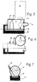
- the position of the melting cyclone (10) relative to the separation chamber (11) is changed so that the entry opening (13) is now arranged in the immediate vicinity of the exhaust gas outlet opening (14), whereby the same design a larger area of the separation chamber (11) remains largely free of exhaust gas (18), so that this area can be used for thermal aftertreatment of the melt (19).
- two inflation lances (20) are introduced secantially into the separation chamber, which, tangentially to the gas flow (29) in the separation chamber (11), spray a gas mixture suitable for the thermal aftertreatment of the melt at an acute angle onto the melt pool surface (16).
- a burner (23) inserted secantially in this area of the separation chamber (41) strikes the free-flowing melt (19) with its active jet at right angles, as a result of which it is atomized and flung against the separation chamber inner wall (39) opposite the burner (23) and flows along this inner wall (37) downwards into the melt pool (38) with only a small drop.
- the thermal aftertreatment of the melt (19) achieved in this way is particularly effective since not only the surface area of the melt pool (38), as with the inflation lances (20) of FIGS. 5 to 7, with the reaction gas, but the entire melt ( 19), separated into fine drops, with the reaction gas from the burner (23).
- the separation chamber (31) is arranged upright with a vertical axis, so that here in the separation chamber (31) obliquely downwards onto the surface of the molten bath (16) impinging exhaust gases (18) are deflected in the direction of the arrow (29) in accordance with the cyclone-like design of the separation chamber (31) and guided to the upper exhaust gas outlet opening (25).
- An advantage of this arrangement is that the hot melt under the separation chamber wall (28) is pressed through the exhaust gas flow into the siphon-like melt discharge area (26), which significantly facilitates the continuous discharge of the melt (19) and also without an additional burner (27) Prevents "freezing" of the melt in this area.
- the improvement of the thermal treatment as a whole as well as the lowering of the operating costs can also be influenced by suitable measures during the thermal treatment in the melting cyclone.
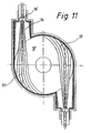
- the combustion chamber (36) with the burner (30 ') of the melting cyclone (10') is extended to the rear outside the melting cyclone (10 '), so that the entire burning distance until the burner jet (37) hits is extended to the inner wall of the melting cyclone.
Landscapes
- Engineering & Computer Science (AREA)
- Chemical & Material Sciences (AREA)
- Materials Engineering (AREA)
- Organic Chemistry (AREA)
- Mechanical Engineering (AREA)
- General Engineering & Computer Science (AREA)
- Physics & Mathematics (AREA)
- Plasma & Fusion (AREA)
- Cyclones (AREA)
- Gasification And Melting Of Waste (AREA)
- Manufacture And Refinement Of Metals (AREA)
- Processing Of Solid Wastes (AREA)
Applications Claiming Priority (2)
| Application Number | Priority Date | Filing Date | Title |
|---|---|---|---|
| DE19504082 | 1995-02-08 | ||
| DE19504082A DE19504082A1 (de) | 1995-02-08 | 1995-02-08 | Verfahren und Vorrichtung zur thermischen Behandlung von Feststoffen |
Publications (2)
| Publication Number | Publication Date |
|---|---|
| EP0726231A1 true EP0726231A1 (fr) | 1996-08-14 |
| EP0726231B1 EP0726231B1 (fr) | 2001-05-16 |
Family
ID=7753424
Family Applications (1)
| Application Number | Title | Priority Date | Filing Date |
|---|---|---|---|
| EP96101026A Expired - Lifetime EP0726231B1 (fr) | 1995-02-08 | 1996-01-25 | Procédé et appareil pour le traitement thermique de matières solides |
Country Status (5)
| Country | Link |
|---|---|
| US (1) | US5700144A (fr) |
| EP (1) | EP0726231B1 (fr) |
| AT (1) | ATE201189T1 (fr) |
| DE (2) | DE19504082A1 (fr) |
| ZA (1) | ZA96477B (fr) |
Families Citing this family (2)
| Publication number | Priority date | Publication date | Assignee | Title |
|---|---|---|---|---|
| DE19735153C2 (de) * | 1997-08-13 | 2003-10-16 | Linde Kca Dresden Gmbh | Verfahren und Vorrichtung zur Vergasung von Abfallstoffen |
| JP5847464B2 (ja) * | 2011-07-07 | 2016-01-20 | 興亜硝子株式会社 | 管状火炎バーナ及びガラス加工方法 |
Citations (7)
| Publication number | Priority date | Publication date | Assignee | Title |
|---|---|---|---|---|
| US2115125A (en) * | 1935-11-21 | 1938-04-26 | Sinclair Harold | Control means for internal combustion engines |
| FR918989A (fr) * | 1945-12-05 | 1947-02-24 | Brûleur à turbulence pour combustibles en général | |
| US3510289A (en) * | 1963-08-22 | 1970-05-05 | Saint Gobain | Cyclone type glass furnace |
| US4544394A (en) * | 1984-03-05 | 1985-10-01 | Hnat James G | Vortex process for melting glass |
| DE3536635A1 (de) * | 1985-10-15 | 1987-04-23 | Kloeckner Humboldt Deutz Ag | Verfahren und vorrichtung zur rueckgewinnung, insbesondere von eisen sowie von zink, blei und anderen ne-metallischen bestandteilen aus hocheisenhaltigen oxydischen materialien |
| EP0436759A1 (fr) * | 1990-01-11 | 1991-07-17 | Chiba City | Système de traitement des déchets à l'état fondu |
| EP0520533A2 (fr) * | 1991-06-28 | 1992-12-30 | METALLGESELLSCHAFT Aktiengesellschaft | Procédé pour la combustion des déchets |
Family Cites Families (4)
| Publication number | Priority date | Publication date | Assignee | Title |
|---|---|---|---|---|
| US2745733A (en) * | 1952-10-24 | 1956-05-15 | Ford Motor Co | Apparatus and process for reduction of ores to metal |
| DE3420372A1 (de) * | 1984-06-01 | 1985-12-05 | Klöckner-Humboldt-Deutz AG, 5000 Köln | Verfahren und einrichtung zur behandlung von schmelzfluessigen nichteisenmetallen und/oder deren schlacken durch aufblasen von reaktionsgasen |
| DE3638204A1 (de) * | 1986-11-08 | 1988-05-11 | Kloeckner Humboldt Deutz Ag | Verfahren und vorrichtung zur verhuettung schmelzbarer stoffe wie erzkonzentrat unter ausnuetzung des unverbrauchten reduktionsgases aus dem aufblasprozess im schmelzzyklon |
| DE3729798A1 (de) * | 1987-09-05 | 1989-03-16 | Kloeckner Humboldt Deutz Ag | Vorrichtung zur verhuettung von schmelzbaren stoffen, insbesondere von erzkonzentraten |
-
1995
- 1995-02-08 DE DE19504082A patent/DE19504082A1/de not_active Withdrawn
-
1996
- 1996-01-22 ZA ZA96477A patent/ZA96477B/xx unknown
- 1996-01-25 EP EP96101026A patent/EP0726231B1/fr not_active Expired - Lifetime
- 1996-01-25 DE DE59606888T patent/DE59606888D1/de not_active Expired - Fee Related
- 1996-01-25 AT AT96101026T patent/ATE201189T1/de not_active IP Right Cessation
- 1996-02-07 US US08/598,032 patent/US5700144A/en not_active Expired - Fee Related
Patent Citations (7)
| Publication number | Priority date | Publication date | Assignee | Title |
|---|---|---|---|---|
| US2115125A (en) * | 1935-11-21 | 1938-04-26 | Sinclair Harold | Control means for internal combustion engines |
| FR918989A (fr) * | 1945-12-05 | 1947-02-24 | Brûleur à turbulence pour combustibles en général | |
| US3510289A (en) * | 1963-08-22 | 1970-05-05 | Saint Gobain | Cyclone type glass furnace |
| US4544394A (en) * | 1984-03-05 | 1985-10-01 | Hnat James G | Vortex process for melting glass |
| DE3536635A1 (de) * | 1985-10-15 | 1987-04-23 | Kloeckner Humboldt Deutz Ag | Verfahren und vorrichtung zur rueckgewinnung, insbesondere von eisen sowie von zink, blei und anderen ne-metallischen bestandteilen aus hocheisenhaltigen oxydischen materialien |
| EP0436759A1 (fr) * | 1990-01-11 | 1991-07-17 | Chiba City | Système de traitement des déchets à l'état fondu |
| EP0520533A2 (fr) * | 1991-06-28 | 1992-12-30 | METALLGESELLSCHAFT Aktiengesellschaft | Procédé pour la combustion des déchets |
Also Published As
| Publication number | Publication date |
|---|---|
| EP0726231B1 (fr) | 2001-05-16 |
| US5700144A (en) | 1997-12-23 |
| ZA96477B (en) | 1996-09-04 |
| DE19504082A1 (de) | 1996-08-22 |
| DE59606888D1 (de) | 2001-06-21 |
| ATE201189T1 (de) | 2001-06-15 |
Similar Documents
| Publication | Publication Date | Title |
|---|---|---|
| DE3405462C2 (de) | Schwebeschmelzverfahren unter Zufuhr von Zusatzgas in den Reaktionsschacht | |
| DE60225724T2 (de) | Metallschmelzepumpe und Ofen | |
| DE69002605T2 (de) | System für die Behandlung von Müll in geschmolzenem Zustand. | |
| DE60019680T2 (de) | Direktschmelzofen | |
| DE2322338C2 (de) | Verfahren und Vorrichtung zum Reinigen von Abgasen bei der Stahlherstellung | |
| DE69132590T3 (de) | Raffinationsofen für Kupfer | |
| DE2922189C2 (de) | Verfahren und Vorrichtung zur Verhütung von schmelzbaren Stoffen wie Erzkonzentrat | |
| EP0487494B1 (fr) | Installation pour la production de métaux fondus | |
| AT411363B (de) | Einrichtung zum schmelzen von stäuben | |
| DE10297306T5 (de) | U-förmiger Schmelzkammerverbrennungskessel und Verfahren zum Betrieb des Kessels | |
| DE19640497C2 (de) | Koksbeheizter Kreislaufgaskupolofen zur stofflichen und/oder energetischen Verwertung von Abfallmaterialien | |
| EP1664355B2 (fr) | Procede pour accumuler et traiter des gaz reactionnels issus d'une installation de production pour metaux en fusion, et installation de depoussierage a cet effet | |
| DE3412964C2 (de) | Vorrichtung zum Schmelzen von Metallschrott und/oder Gröbe | |
| DE3101369C2 (de) | Verfahren zur Verhüttung von feinkörnigem sulfidischen Kupfererzkonzentrat | |
| EP0726231B1 (fr) | Procédé et appareil pour le traitement thermique de matières solides | |
| DE19806823A1 (de) | Vorrichtung und Verfahren zur Verbrennung vanadiumhaltiger Brennstoffe | |
| DE3304885C2 (de) | Einrichtung zum Absondern von Fest- und Schmelzteilchen aus den Abgasen Metallurgischer Öfen | |
| DE4115348A1 (de) | Verfahren und vorrichtung zur hochtemperaturbehandlung von feinkoernigen feststoffen in einem schmelzzyklon | |
| AU773241B2 (en) | Method for cooling the gas flow in a smelting furnace | |
| DE19637246A1 (de) | Schmelzofen insbesondere für Metalle mit zumindest einer in seinen Ofenraum einragenden Lanze, Lanze dafür sowie Verfahren zu deren Steuerung | |
| DE2905089A1 (de) | Verfahren und vorrichtung zur energierueckgewinnung beim schmelzen von glas | |
| EP0193976A1 (fr) | Installation pour le traitement pyrométallurgique de matières solides pulvérulentes avec obtention de produits fondus | |
| WO1991002095A1 (fr) | Dispositif d'introduction de dechets industriels dans du laitier en fusion | |
| DE2725813A1 (de) | Metallurgischer schachtofen | |
| DE2932938A1 (de) | Metallurgisches schmelzaggregat, insbesondere lichtbogenofen |
Legal Events
| Date | Code | Title | Description |
|---|---|---|---|
| PUAI | Public reference made under article 153(3) epc to a published international application that has entered the european phase |
Free format text: ORIGINAL CODE: 0009012 |
|
| AK | Designated contracting states |
Kind code of ref document: A1 Designated state(s): AT BE CH DE FR IT LI NL |
|
| 17P | Request for examination filed |
Effective date: 19970213 |
|
| RAP1 | Party data changed (applicant data changed or rights of an application transferred) |
Owner name: DEUTZ AKTIENGESELLSCHAFT |
|
| 17Q | First examination report despatched |
Effective date: 19990526 |
|
| GRAG | Despatch of communication of intention to grant |
Free format text: ORIGINAL CODE: EPIDOS AGRA |
|
| GRAG | Despatch of communication of intention to grant |
Free format text: ORIGINAL CODE: EPIDOS AGRA |
|
| GRAH | Despatch of communication of intention to grant a patent |
Free format text: ORIGINAL CODE: EPIDOS IGRA |
|
| GRAH | Despatch of communication of intention to grant a patent |
Free format text: ORIGINAL CODE: EPIDOS IGRA |
|
| GRAA | (expected) grant |
Free format text: ORIGINAL CODE: 0009210 |
|
| ITF | It: translation for a ep patent filed | ||
| AK | Designated contracting states |
Kind code of ref document: B1 Designated state(s): AT BE CH DE FR IT LI NL |
|
| REF | Corresponds to: |
Ref document number: 201189 Country of ref document: AT Date of ref document: 20010615 Kind code of ref document: T |
|
| REG | Reference to a national code |
Ref country code: CH Ref legal event code: EP |
|
| REF | Corresponds to: |
Ref document number: 59606888 Country of ref document: DE Date of ref document: 20010621 |
|
| ET | Fr: translation filed | ||
| REG | Reference to a national code |
Ref country code: CH Ref legal event code: NV Representative=s name: R. A. EGLI & CO. PATENTANWAELTE |
|
| PLBE | No opposition filed within time limit |
Free format text: ORIGINAL CODE: 0009261 |
|
| STAA | Information on the status of an ep patent application or granted ep patent |
Free format text: STATUS: NO OPPOSITION FILED WITHIN TIME LIMIT |
|
| 26N | No opposition filed | ||
| PG25 | Lapsed in a contracting state [announced via postgrant information from national office to epo] |
Ref country code: IT Free format text: LAPSE BECAUSE OF NON-PAYMENT OF DUE FEES;WARNING: LAPSES OF ITALIAN PATENTS WITH EFFECTIVE DATE BEFORE 2007 MAY HAVE OCCURRED AT ANY TIME BEFORE 2007. THE CORRECT EFFECTIVE DATE MAY BE DIFFERENT FROM THE ONE RECORDED. Effective date: 20050125 |
|
| PGFP | Annual fee paid to national office [announced via postgrant information from national office to epo] |
Ref country code: FR Payment date: 20051208 Year of fee payment: 11 |
|
| PGFP | Annual fee paid to national office [announced via postgrant information from national office to epo] |
Ref country code: AT Payment date: 20051209 Year of fee payment: 11 |
|
| PGFP | Annual fee paid to national office [announced via postgrant information from national office to epo] |
Ref country code: NL Payment date: 20051214 Year of fee payment: 11 |
|
| PGFP | Annual fee paid to national office [announced via postgrant information from national office to epo] |
Ref country code: CH Payment date: 20051220 Year of fee payment: 11 |
|
| PGFP | Annual fee paid to national office [announced via postgrant information from national office to epo] |
Ref country code: BE Payment date: 20060120 Year of fee payment: 11 |
|
| PGFP | Annual fee paid to national office [announced via postgrant information from national office to epo] |
Ref country code: DE Payment date: 20060324 Year of fee payment: 11 |
|
| PG25 | Lapsed in a contracting state [announced via postgrant information from national office to epo] |
Ref country code: LI Free format text: LAPSE BECAUSE OF NON-PAYMENT OF DUE FEES Effective date: 20070131 Ref country code: CH Free format text: LAPSE BECAUSE OF NON-PAYMENT OF DUE FEES Effective date: 20070131 |
|
| PG25 | Lapsed in a contracting state [announced via postgrant information from national office to epo] |
Ref country code: DE Free format text: LAPSE BECAUSE OF NON-PAYMENT OF DUE FEES Effective date: 20070801 |
|
| REG | Reference to a national code |
Ref country code: CH Ref legal event code: PL |
|
| NLV4 | Nl: lapsed or anulled due to non-payment of the annual fee |
Effective date: 20070801 |
|
| REG | Reference to a national code |
Ref country code: FR Ref legal event code: ST Effective date: 20070930 |
|
| PG25 | Lapsed in a contracting state [announced via postgrant information from national office to epo] |
Ref country code: AT Free format text: LAPSE BECAUSE OF NON-PAYMENT OF DUE FEES Effective date: 20070125 |
|
| BERE | Be: lapsed |
Owner name: *DEUTZ A.G. Effective date: 20070131 |
|
| PG25 | Lapsed in a contracting state [announced via postgrant information from national office to epo] |
Ref country code: BE Free format text: LAPSE BECAUSE OF NON-PAYMENT OF DUE FEES Effective date: 20070131 |
|
| PG25 | Lapsed in a contracting state [announced via postgrant information from national office to epo] |
Ref country code: NL Free format text: LAPSE BECAUSE OF NON-PAYMENT OF DUE FEES Effective date: 20070801 |
|
| PG25 | Lapsed in a contracting state [announced via postgrant information from national office to epo] |
Ref country code: FR Free format text: LAPSE BECAUSE OF NON-PAYMENT OF DUE FEES Effective date: 20070131 |