EP0726446A2 - Verbesserungen an Oberflächenkrümmungsmessungen - Google Patents
Verbesserungen an Oberflächenkrümmungsmessungen Download PDFInfo
- Publication number
- EP0726446A2 EP0726446A2 EP96101238A EP96101238A EP0726446A2 EP 0726446 A2 EP0726446 A2 EP 0726446A2 EP 96101238 A EP96101238 A EP 96101238A EP 96101238 A EP96101238 A EP 96101238A EP 0726446 A2 EP0726446 A2 EP 0726446A2
- Authority
- EP
- European Patent Office
- Prior art keywords
- beams
- cos
- sin
- lens
- detector
- Prior art date
- Legal status (The legal status is an assumption and is not a legal conclusion. Google has not performed a legal analysis and makes no representation as to the accuracy of the status listed.)
- Granted
Links
- 238000005259 measurement Methods 0.000 title claims description 10
- 230000005670 electromagnetic radiation Effects 0.000 claims description 7
- 238000000926 separation method Methods 0.000 claims description 7
- 238000010586 diagram Methods 0.000 description 4
- 238000000034 method Methods 0.000 description 4
- 239000000523 sample Substances 0.000 description 2
- 238000003754 machining Methods 0.000 description 1
- 238000000691 measurement method Methods 0.000 description 1
- 238000005070 sampling Methods 0.000 description 1
Images


Classifications
-
- G—PHYSICS
- G01—MEASURING; TESTING
- G01B—MEASURING LENGTH, THICKNESS OR SIMILAR LINEAR DIMENSIONS; MEASURING ANGLES; MEASURING AREAS; MEASURING IRREGULARITIES OF SURFACES OR CONTOURS
- G01B11/00—Measuring arrangements characterised by the use of optical techniques
- G01B11/24—Measuring arrangements characterised by the use of optical techniques for measuring contours or curvatures
- G01B11/255—Measuring arrangements characterised by the use of optical techniques for measuring contours or curvatures for measuring radius of curvature
Definitions
- the invention relates to apparatus for the measurement of the radius of curvature of at least a partially reflective surface.
- An aim of the present invention is to provide apparatus which effectively measures the radius of curvature of the surface of at least a partially reflective surface.
- apparatus for the measurement of the radius of curvature of a surface being at least partially reflective comprising a source for generating at least first and second beams of electromagnetic radiation, which are parallel to each other and a known distance apart, first lens means for focusing said beams, a beam splitter positioned between said first lens means and said surface, second lens means positioned between said beam splitter and said surface, electromagnetic radiation detector means arranged to receive at least said first and second beams which are reflected from said surface via said second lens means and said beam splitter, and processing means for calculating said measurement in dependence upon the position of the reflected beams on the detector.
- the apparatus shown may be hand-held, but it will be appreciated that the apparatus may be fixed to a lathe stock or robot arm, for example.
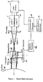
- the hand-held apparatus comprises first and second sources of electromagnetic radiation 2, 4, which are lasers.
- the lasers are driven by laser drivers 6, which are controlled by a controller and processor circuit 8 having a man machine interface input 10.
- the lasers 2, 4 each produce a beam of electromagnetic radiation, which is passed through a focusing lens 12 into a beam splitter 14.
- the beams are parallel to each other and are a known distance apart.
- the beams pass through the beam splitter and into a transform lens 16, which directs beams towards a surface 18 to be measured.
- This surface may be a lens but could be any reflective or partially reflective surface which requires the radius of curvature to be measured.
- the surface reflects the beams 1, 2 back towards the transform lens, which in turn pass into the beam splitter and are directed onto the surface of a detector 20.
- These beams are identified as X1, X2,
- a detector processor 22 is arranged to calculate the radius of curvature of the surface based upon the positions of the reflected beams X1, X2 on the surface of the detector and upon the separation of the two beams at the surface 18.
- the detector 22 is controlled by the controller and processor circuit 8.
- the lasers are diode lasers 2, 4 which emit in the visible range of wavelengths, and will thereby provide an indication to an operator of where the measurements are actually being made.
- the lasers emit collimated beams which are directed to a surface to be measured by various lenses and prisms as shown in Figure 1.
- the beams are parallel with each other, and are a known distance apart.
- the measurement method used is non-contact and potentially more accurate than a method using a spherometer, which is a contact instrument.
- a spherometer which is a contact instrument.
- two parallel beams, beam 1 and beam 2 a known distance apart impinge on a surface.
- the positions are stored in a memory in the detector processor 22 and used to calculate the radius of curvature.
- FIG 3 a variation of the device shown in Figure 1 will now be discussed and shows a multibeam variant. Similar elements in Figure 3 have been given the same designation as that of Figure 1 and their functions are the same.
- the difference between Figure 1 and Figure 3 is that the electro-magnetic source 2, 4 in Figure 1, which were lasers, have been replaced by a discrete beam generator 24 which is driven by a laser and a laser driver 26.
- the discrete beam generator generates a plurality of beams, beam 1 to beam N, which are all parallel and where the distance X is known between any two beams.
- the beams are passed through the focusing lens 12 and thereafter are treated in exactly in the same manner as that discussed in relation to Figure 1.
- a probe beam is scanned across the surface by having, for example, a scanning mirror/prism and appropriate optics, or an LCD light shutter, located in a discrete beam generator 24 in Figure 3, thus providing continuous, or variable, sample intervals for providing a profile of the surface.
- FIGURE 4 is a block diagram of apparatus similar to Figure 1, having an additional device 28 positioned between the surface to be measured 18 and the transform lens 16. Identical elements bear the same designations as in Figure 1 and their operation is the same.
- the device 28 is effective to increase, or decrease, beam separation by having add-on optics which is attached to the transform lens 16, for example.
- the device 28 permits different sizes of lenses and different radii of curvature to be determined with accuracy.
- the measurements could be accomplished in real time such that as a surface is machined the output from the unit is used to control a cutting tool, thus providing an automatic system which may be used to modify the machining as required, or stop when the required radius of curvature, or profile, is accomplished.
- the units shown are eminently suitable for a hand held design, when the measurements are made the unit could, for example, alternatively be affixed to a lathe stock or temporarily affixed near a surface to be tested.
- the beam splitter described is intended to include any means for causing beam separation, for example, partially reflective mirrors.
Landscapes
- Physics & Mathematics (AREA)
- General Physics & Mathematics (AREA)
- Length Measuring Devices By Optical Means (AREA)
- Length Measuring Devices With Unspecified Measuring Means (AREA)
- Testing Of Optical Devices Or Fibers (AREA)
- Analysing Materials By The Use Of Radiation (AREA)
- Sampling And Sample Adjustment (AREA)
- Measurement Of Length, Angles, Or The Like Using Electric Or Magnetic Means (AREA)
- Investigating Strength Of Materials By Application Of Mechanical Stress (AREA)
- A Measuring Device Byusing Mechanical Method (AREA)
Applications Claiming Priority (4)
| Application Number | Priority Date | Filing Date | Title |
|---|---|---|---|
| GBGB9502710.8A GB9502710D0 (en) | 1995-02-11 | 1995-02-11 | Improvements in or relating to surface curvature measurement |
| GB9502710 | 1995-02-11 | ||
| GB9524883A GB2297836B (en) | 1995-02-11 | 1995-12-05 | Improvements in or relating to surface curvature measurement |
| GB9524883 | 1995-12-05 |
Publications (3)
| Publication Number | Publication Date |
|---|---|
| EP0726446A2 true EP0726446A2 (de) | 1996-08-14 |
| EP0726446A3 EP0726446A3 (de) | 1997-12-10 |
| EP0726446B1 EP0726446B1 (de) | 2002-08-14 |
Family
ID=26306488
Family Applications (1)
| Application Number | Title | Priority Date | Filing Date |
|---|---|---|---|
| EP96101238A Expired - Lifetime EP0726446B1 (de) | 1995-02-11 | 1996-01-26 | Verbesserungen an Oberflächenkrümmungsmessungen |
Country Status (7)
| Country | Link |
|---|---|
| US (1) | US5633718A (de) |
| EP (1) | EP0726446B1 (de) |
| JP (1) | JP3294985B2 (de) |
| AT (1) | ATE222349T1 (de) |
| AU (1) | AU4225796A (de) |
| DE (1) | DE69622896T2 (de) |
| ES (1) | ES2181814T3 (de) |
Cited By (1)
| Publication number | Priority date | Publication date | Assignee | Title |
|---|---|---|---|---|
| DE19851176A1 (de) * | 1998-11-06 | 2000-05-11 | Zeiss Carl Jena Gmbh | Anordnung zur Bestimmung von Krümmungsradien |
Families Citing this family (13)
| Publication number | Priority date | Publication date | Assignee | Title |
|---|---|---|---|---|
| US6075604A (en) * | 1998-11-10 | 2000-06-13 | International Business Machines Corporation | Apparatus for measuring curvature of magnetic read/write head sliders |
| US6538817B1 (en) * | 1999-10-25 | 2003-03-25 | Aculight Corporation | Method and apparatus for optical coherence tomography with a multispectral laser source |
| KR100556612B1 (ko) * | 2002-06-29 | 2006-03-06 | 삼성전자주식회사 | 레이저를 이용한 위치 측정 장치 및 방법 |
| DE20306904U1 (de) * | 2003-05-02 | 2003-09-04 | Otto-von-Guericke-Universität Magdeburg, 39106 Magdeburg | Vorrichtung zur Messung der Schichtdicke und der Krümmung von mindestens teilweise reflektierenden Oberflächen von Schichten |
| DK1528411T3 (da) * | 2003-10-27 | 2010-05-17 | Bea Sa | Sensor til afstandsmåling |
| US7570368B2 (en) * | 2004-05-12 | 2009-08-04 | Veeco Instruments Inc. | Method and apparatus for measuring the curvature of reflective surfaces |
| FR2879736B1 (fr) * | 2004-12-20 | 2007-02-02 | Essilor Int | Procede et dispositif de mesure sans contact de la courbure d'un objet ophtalmique |
| JP5611168B2 (ja) * | 2011-10-24 | 2014-10-22 | 信越化学工業株式会社 | 光ファイバの曲率の測定方法 |
| JP6430307B2 (ja) * | 2014-03-27 | 2018-11-28 | 株式会社ニューフレアテクノロジー | 曲率測定装置及び曲率測定方法 |
| TWI506242B (zh) * | 2014-12-12 | 2015-11-01 | Ind Tech Res Inst | 薄膜曲率量測裝置及其方法 |
| TWI624643B (zh) * | 2016-08-19 | 2018-05-21 | 財團法人工業技術研究院 | 一種薄膜曲率量測裝置及其方法 |
| US20180059219A1 (en) * | 2016-08-31 | 2018-03-01 | Qualcomm Incorporated | Multi-beam position sensing devices |
| JP2020512564A (ja) | 2017-03-29 | 2020-04-23 | ラトガース,ザ ステート ユニバーシティ オブ ニュー ジャージー | 小サンプルの表面曲率および熱膨張のリアルタイム測定のためのシステムと方法 |
Citations (1)
| Publication number | Priority date | Publication date | Assignee | Title |
|---|---|---|---|---|
| GB2265215B (en) | 1992-03-14 | 1995-12-06 | Roke Manor Research | Improvements in or relating to surface curvature measurement |
Family Cites Families (2)
| Publication number | Priority date | Publication date | Assignee | Title |
|---|---|---|---|---|
| US4735508A (en) * | 1986-06-02 | 1988-04-05 | Honeywell Inc. | Method and apparatus for measuring a curvature of a reflective surface |
| US5067817A (en) * | 1990-02-08 | 1991-11-26 | Bauer Associates, Inc. | Method and device for noncontacting self-referencing measurement of surface curvature and profile |
-
1996
- 1996-01-26 ES ES96101238T patent/ES2181814T3/es not_active Expired - Lifetime
- 1996-01-26 AT AT96101238T patent/ATE222349T1/de not_active IP Right Cessation
- 1996-01-26 DE DE69622896T patent/DE69622896T2/de not_active Expired - Fee Related
- 1996-01-26 EP EP96101238A patent/EP0726446B1/de not_active Expired - Lifetime
- 1996-01-30 AU AU42257/96A patent/AU4225796A/en not_active Abandoned
- 1996-02-05 US US08/597,085 patent/US5633718A/en not_active Expired - Fee Related
- 1996-02-09 JP JP02395396A patent/JP3294985B2/ja not_active Expired - Fee Related
Patent Citations (1)
| Publication number | Priority date | Publication date | Assignee | Title |
|---|---|---|---|---|
| GB2265215B (en) | 1992-03-14 | 1995-12-06 | Roke Manor Research | Improvements in or relating to surface curvature measurement |
Cited By (2)
| Publication number | Priority date | Publication date | Assignee | Title |
|---|---|---|---|---|
| DE19851176A1 (de) * | 1998-11-06 | 2000-05-11 | Zeiss Carl Jena Gmbh | Anordnung zur Bestimmung von Krümmungsradien |
| DE19851176B4 (de) * | 1998-11-06 | 2010-10-14 | Carl Zeiss Meditec Ag | Anordnung zur Bestimmung von Krümmungsradien |
Also Published As
| Publication number | Publication date |
|---|---|
| EP0726446B1 (de) | 2002-08-14 |
| ES2181814T3 (es) | 2003-03-01 |
| AU4225796A (en) | 1996-08-22 |
| JPH08247741A (ja) | 1996-09-27 |
| DE69622896D1 (de) | 2002-09-19 |
| EP0726446A3 (de) | 1997-12-10 |
| US5633718A (en) | 1997-05-27 |
| JP3294985B2 (ja) | 2002-06-24 |
| ATE222349T1 (de) | 2002-08-15 |
| DE69622896T2 (de) | 2002-12-05 |
Similar Documents
| Publication | Publication Date | Title |
|---|---|---|
| US5633718A (en) | Surface curvature measurement | |
| US4983043A (en) | High accuracy structured light profiler | |
| US7483150B2 (en) | Measuring device having an optical probe tip | |
| EP0330429B1 (de) | Verfahren und Apparat zur Ueberwachung des Oberflächenprofils eines Werkstückes | |
| EP0015506B1 (de) | Messvorrichtung für Abstandsänderung mit einer Laserlichtquelle | |
| US4355904A (en) | Optical inspection device for measuring depthwise variations from a focal plane | |
| EP0632292B1 (de) | Geschwindigkeitsmesser und Anlage zur Positionserfassung | |
| US3768910A (en) | Detecting the position of a surface by focus modulating the illuminating beam | |
| EP0629835B1 (de) | Deformationsmessinstrument | |
| EP0711402B1 (de) | Verbesserung an einem in bezug auf ein gerat zum messen der krummung einer oberflache | |
| EP2306142A1 (de) | Vorrichtung zur Messung der Oberflächenform | |
| US4088408A (en) | Device for measuring the contour of a surface | |
| GB1575054A (en) | Method of and apparatus for laser-beam processing of a workpiece | |
| US5012090A (en) | Optical grating sensor and method of monitoring having a multi-period grating | |
| EP0561178B1 (de) | Krümmungsmessung einer Oberfläche | |
| GB2265215A (en) | Optical apparatus for measuring surface curvature | |
| US4925301A (en) | Method and apparatus for sensing the figure of optical elements | |
| US4425041A (en) | Measuring apparatus | |
| US7433128B1 (en) | Adaptive light-path surface tilt sensor for machine vision inspection | |
| JPH0914935A (ja) | 3次元物体の測定装置 | |
| GB2297836A (en) | Surface curvature measurement of a reflective surface | |
| US11686570B2 (en) | Displacement sensor and profile measurement apparatus | |
| US4685804A (en) | Method and apparatus for the measurement of the location or movement of a body | |
| EP0427692A2 (de) | Berührungsloser Messtaster | |
| Harding et al. | Hybrid, high accuracy structured light profiler |
Legal Events
| Date | Code | Title | Description |
|---|---|---|---|
| PUAI | Public reference made under article 153(3) epc to a published international application that has entered the european phase |
Free format text: ORIGINAL CODE: 0009012 |
|
| AK | Designated contracting states |
Kind code of ref document: A2 Designated state(s): AT BE CH DE DK ES FR GB GR IE IT LI LU MC NL PT SE |
|
| 17P | Request for examination filed |
Effective date: 19970122 |
|
| PUAL | Search report despatched |
Free format text: ORIGINAL CODE: 0009013 |
|
| AK | Designated contracting states |
Kind code of ref document: A3 Designated state(s): AT BE CH DE DK ES FR GB GR IE IT LI LU MC NL PT SE |
|
| 17Q | First examination report despatched |
Effective date: 19991209 |
|
| GRAG | Despatch of communication of intention to grant |
Free format text: ORIGINAL CODE: EPIDOS AGRA |
|
| GRAG | Despatch of communication of intention to grant |
Free format text: ORIGINAL CODE: EPIDOS AGRA |
|
| GRAH | Despatch of communication of intention to grant a patent |
Free format text: ORIGINAL CODE: EPIDOS IGRA |
|
| GRAH | Despatch of communication of intention to grant a patent |
Free format text: ORIGINAL CODE: EPIDOS IGRA |
|
| GRAA | (expected) grant |
Free format text: ORIGINAL CODE: 0009210 |
|
| AK | Designated contracting states |
Kind code of ref document: B1 Designated state(s): AT BE CH DE DK ES FR GB GR IE IT LI LU MC NL PT SE |
|
| PG25 | Lapsed in a contracting state [announced via postgrant information from national office to epo] |
Ref country code: NL Free format text: LAPSE BECAUSE OF FAILURE TO SUBMIT A TRANSLATION OF THE DESCRIPTION OR TO PAY THE FEE WITHIN THE PRESCRIBED TIME-LIMIT Effective date: 20020814 Ref country code: LI Free format text: LAPSE BECAUSE OF FAILURE TO SUBMIT A TRANSLATION OF THE DESCRIPTION OR TO PAY THE FEE WITHIN THE PRESCRIBED TIME-LIMIT Effective date: 20020814 Ref country code: GR Free format text: LAPSE BECAUSE OF FAILURE TO SUBMIT A TRANSLATION OF THE DESCRIPTION OR TO PAY THE FEE WITHIN THE PRESCRIBED TIME-LIMIT Effective date: 20020814 Ref country code: CH Free format text: LAPSE BECAUSE OF FAILURE TO SUBMIT A TRANSLATION OF THE DESCRIPTION OR TO PAY THE FEE WITHIN THE PRESCRIBED TIME-LIMIT Effective date: 20020814 Ref country code: BE Free format text: LAPSE BECAUSE OF FAILURE TO SUBMIT A TRANSLATION OF THE DESCRIPTION OR TO PAY THE FEE WITHIN THE PRESCRIBED TIME-LIMIT Effective date: 20020814 Ref country code: AT Free format text: LAPSE BECAUSE OF FAILURE TO SUBMIT A TRANSLATION OF THE DESCRIPTION OR TO PAY THE FEE WITHIN THE PRESCRIBED TIME-LIMIT Effective date: 20020814 |
|
| REF | Corresponds to: |
Ref document number: 222349 Country of ref document: AT Date of ref document: 20020815 Kind code of ref document: T |
|
| REG | Reference to a national code |
Ref country code: GB Ref legal event code: FG4D |
|
| REG | Reference to a national code |
Ref country code: CH Ref legal event code: EP |
|
| REG | Reference to a national code |
Ref country code: IE Ref legal event code: FG4D |
|
| REF | Corresponds to: |
Ref document number: 69622896 Country of ref document: DE Date of ref document: 20020919 |
|
| PG25 | Lapsed in a contracting state [announced via postgrant information from national office to epo] |
Ref country code: SE Free format text: LAPSE BECAUSE OF FAILURE TO SUBMIT A TRANSLATION OF THE DESCRIPTION OR TO PAY THE FEE WITHIN THE PRESCRIBED TIME-LIMIT Effective date: 20021114 Ref country code: DK Free format text: LAPSE BECAUSE OF FAILURE TO SUBMIT A TRANSLATION OF THE DESCRIPTION OR TO PAY THE FEE WITHIN THE PRESCRIBED TIME-LIMIT Effective date: 20021114 |
|
| PG25 | Lapsed in a contracting state [announced via postgrant information from national office to epo] |
Ref country code: PT Free format text: LAPSE BECAUSE OF FAILURE TO SUBMIT A TRANSLATION OF THE DESCRIPTION OR TO PAY THE FEE WITHIN THE PRESCRIBED TIME-LIMIT Effective date: 20021128 |
|
| ET | Fr: translation filed | ||
| PGFP | Annual fee paid to national office [announced via postgrant information from national office to epo] |
Ref country code: LU Payment date: 20030128 Year of fee payment: 8 |
|
| PGFP | Annual fee paid to national office [announced via postgrant information from national office to epo] |
Ref country code: MC Payment date: 20030131 Year of fee payment: 8 |
|
| NLV1 | Nl: lapsed or annulled due to failure to fulfill the requirements of art. 29p and 29m of the patents act | ||
| REG | Reference to a national code |
Ref country code: CH Ref legal event code: PL |
|
| REG | Reference to a national code |
Ref country code: ES Ref legal event code: FG2A Ref document number: 2181814 Country of ref document: ES Kind code of ref document: T3 |
|
| PLBE | No opposition filed within time limit |
Free format text: ORIGINAL CODE: 0009261 |
|
| STAA | Information on the status of an ep patent application or granted ep patent |
Free format text: STATUS: NO OPPOSITION FILED WITHIN TIME LIMIT |
|
| 26N | No opposition filed |
Effective date: 20030515 |
|
| PGFP | Annual fee paid to national office [announced via postgrant information from national office to epo] |
Ref country code: FR Payment date: 20040108 Year of fee payment: 9 |
|
| PGFP | Annual fee paid to national office [announced via postgrant information from national office to epo] |
Ref country code: GB Payment date: 20040121 Year of fee payment: 9 |
|
| PGFP | Annual fee paid to national office [announced via postgrant information from national office to epo] |
Ref country code: IE Payment date: 20040122 Year of fee payment: 9 |
|
| PGFP | Annual fee paid to national office [announced via postgrant information from national office to epo] |
Ref country code: ES Payment date: 20040123 Year of fee payment: 9 |
|
| PG25 | Lapsed in a contracting state [announced via postgrant information from national office to epo] |
Ref country code: LU Free format text: LAPSE BECAUSE OF NON-PAYMENT OF DUE FEES Effective date: 20040126 |
|
| PG25 | Lapsed in a contracting state [announced via postgrant information from national office to epo] |
Ref country code: MC Free format text: LAPSE BECAUSE OF NON-PAYMENT OF DUE FEES Effective date: 20040131 |
|
| PGFP | Annual fee paid to national office [announced via postgrant information from national office to epo] |
Ref country code: DE Payment date: 20040205 Year of fee payment: 9 |
|
| PG25 | Lapsed in a contracting state [announced via postgrant information from national office to epo] |
Ref country code: IT Free format text: LAPSE BECAUSE OF NON-PAYMENT OF DUE FEES Effective date: 20050126 Ref country code: IE Free format text: LAPSE BECAUSE OF NON-PAYMENT OF DUE FEES Effective date: 20050126 Ref country code: GB Free format text: LAPSE BECAUSE OF NON-PAYMENT OF DUE FEES Effective date: 20050126 |
|
| PG25 | Lapsed in a contracting state [announced via postgrant information from national office to epo] |
Ref country code: ES Free format text: LAPSE BECAUSE OF NON-PAYMENT OF DUE FEES Effective date: 20050127 |
|
| PG25 | Lapsed in a contracting state [announced via postgrant information from national office to epo] |
Ref country code: DE Free format text: LAPSE BECAUSE OF NON-PAYMENT OF DUE FEES Effective date: 20050802 |
|
| GBPC | Gb: european patent ceased through non-payment of renewal fee |
Effective date: 20050126 |
|
| PG25 | Lapsed in a contracting state [announced via postgrant information from national office to epo] |
Ref country code: FR Free format text: LAPSE BECAUSE OF NON-PAYMENT OF DUE FEES Effective date: 20050930 |
|
| REG | Reference to a national code |
Ref country code: IE Ref legal event code: MM4A |
|
| REG | Reference to a national code |
Ref country code: FR Ref legal event code: ST |
|
| REG | Reference to a national code |
Ref country code: ES Ref legal event code: FD2A Effective date: 20050127 |