EP0726573A2 - Datenspeicherplatte und -kassette - Google Patents
Datenspeicherplatte und -kassette Download PDFInfo
- Publication number
- EP0726573A2 EP0726573A2 EP95308921A EP95308921A EP0726573A2 EP 0726573 A2 EP0726573 A2 EP 0726573A2 EP 95308921 A EP95308921 A EP 95308921A EP 95308921 A EP95308921 A EP 95308921A EP 0726573 A2 EP0726573 A2 EP 0726573A2
- Authority
- EP
- European Patent Office
- Prior art keywords
- cartridge
- tray
- finger
- detente
- write protection
- Prior art date
- Legal status (The legal status is an assumption and is not a legal conclusion. Google has not performed a legal analysis and makes no representation as to the accuracy of the status listed.)
- Withdrawn
Links
- 238000013500 data storage Methods 0.000 title claims abstract description 13
- 230000007246 mechanism Effects 0.000 claims abstract description 44
- 230000003287 optical effect Effects 0.000 claims abstract description 37
- 230000004044 response Effects 0.000 claims description 16
- 239000000463 material Substances 0.000 claims description 9
- 230000003213 activating effect Effects 0.000 claims description 7
- 230000008859 change Effects 0.000 claims description 6
- 230000037431 insertion Effects 0.000 claims description 4
- 238000003780 insertion Methods 0.000 claims description 4
- 239000004033 plastic Substances 0.000 claims description 3
- 239000004417 polycarbonate Substances 0.000 claims description 3
- 229920000515 polycarbonate Polymers 0.000 claims description 3
- 230000004913 activation Effects 0.000 abstract description 2
- 230000008901 benefit Effects 0.000 description 3
- 230000005693 optoelectronics Effects 0.000 description 3
- 239000000284 extract Substances 0.000 description 2
- 238000000465 moulding Methods 0.000 description 2
- 239000000853 adhesive Substances 0.000 description 1
- 230000001070 adhesive effect Effects 0.000 description 1
- 230000000295 complement effect Effects 0.000 description 1
- 230000002265 prevention Effects 0.000 description 1
- 238000009877 rendering Methods 0.000 description 1
- 230000000284 resting effect Effects 0.000 description 1
- 230000007704 transition Effects 0.000 description 1
Images


Classifications
-
- G—PHYSICS
- G11—INFORMATION STORAGE
- G11B—INFORMATION STORAGE BASED ON RELATIVE MOVEMENT BETWEEN RECORD CARRIER AND TRANSDUCER
- G11B23/00—Record carriers not specific to the method of recording or reproducing; Accessories, e.g. containers, specially adapted for co-operation with the recording or reproducing apparatus ; Intermediate mediums; Apparatus or processes specially adapted for their manufacture
- G11B23/28—Indicating or preventing prior or unauthorised use, e.g. cassettes with sealing or locking means, write-protect devices for discs
- G11B23/288—Protecting disks from being written or overwritten
-
- G—PHYSICS
- G11—INFORMATION STORAGE
- G11B—INFORMATION STORAGE BASED ON RELATIVE MOVEMENT BETWEEN RECORD CARRIER AND TRANSDUCER
- G11B23/00—Record carriers not specific to the method of recording or reproducing; Accessories, e.g. containers, specially adapted for co-operation with the recording or reproducing apparatus ; Intermediate mediums; Apparatus or processes specially adapted for their manufacture
- G11B23/28—Indicating or preventing prior or unauthorised use, e.g. cassettes with sealing or locking means, write-protect devices for discs
- G11B23/287—Indicating or preventing prior or unauthorised use, e.g. cassettes with sealing or locking means, write-protect devices for discs by mechanical lock
-
- G—PHYSICS
- G11—INFORMATION STORAGE
- G11B—INFORMATION STORAGE BASED ON RELATIVE MOVEMENT BETWEEN RECORD CARRIER AND TRANSDUCER
- G11B23/00—Record carriers not specific to the method of recording or reproducing; Accessories, e.g. containers, specially adapted for co-operation with the recording or reproducing apparatus ; Intermediate mediums; Apparatus or processes specially adapted for their manufacture
- G11B23/30—Record carriers not specific to the method of recording or reproducing; Accessories, e.g. containers, specially adapted for co-operation with the recording or reproducing apparatus ; Intermediate mediums; Apparatus or processes specially adapted for their manufacture with provision for auxiliary signals
Definitions
- the present invention relates to write protection mechanisms for machine-readable data storage disks, and more particularly, to a write protection system for disks of a single or multiple disk cartridge.
- each diskette includes its own write-protect device.
- these devices are limited in certain other ways. For example, a user cannot access the write protection device of one of these diskettes while the diskette is inserted into a disk drive. The user therefore must remove the diskette from the drive to initiate write protection.
- the invention provides a tray to support a machine-readable data storage disk for use by a disk drive of a computing system or similar, wherein said tray is shaped to be housed within a cartridge that is shaped for slidable insertion into the disk drive, said tray including a write protection mechanism for selectively providing a machine-readable indication of a protection status of the disk, said mechanism including at least one user-activated receiving member to change the indication in response to pressure manually applied by a user, said at least one receiving member being positioned to be accessible when the cartridge is removed from the drive and also when the cartridge is inserted into the drive.
- said cartridge includes a face that is exposed when the cartridge is fully inserted into the disk drive, said tray including an outer edge that is positioned proximate the face when the tray is housed by the cartridge, and wherein said at least one receiving member is positioned along the tray's outer edge.
- the tray is substantially planar and the write protection mechanism comprises a resilient finger attached to the tray and pivotably deformable in a plane parallel to the tray between a first position and a second position in response to pressure applied to the finger; and a resilient detente attached to the tray and including a ramp with an inboard catch facing the finger, wherein said attachment between the detente and the tray urges the ramp toward the finger to slidably contact the finger during pivoting of the finger from the first position to the second position, said catch maintaining the finger at the second position after the finger slides past the catch, said detente being deformably pivotable to release the finger in response to pressure applied to the detente in a direction away from the finger.
- the finger comprises: a resilient base secured to the tray; a tip; and a flag of opaque material interposed between the tip and the base.
- the detente comprises a resilient base secured to the tray; a ramp affixed to the base and having defined therein a channel sized to receive the tip, said ramp including an outer end and an inner end; and a catch provided proximate the ramp's inner end.
- the write protection mechanism comprises a plastic material, such as a polycarbonate material.
- the invention further provides a cartridge for storing machine-readable data storage disks for use in a disk drive of a computing system, said cartridge comprising a cartridge shell for storing and conveying a predetermined number of trays, at least one of said trays being as described above, said shell including a face that is exposed when the cartridge shell is inserted into the disk drive.
- the cartridge shell houses the trays when the disks of the respective trays are not being accessed by said disk drive.
- the cartridge includes a transparent window aligned with the write protection mechanism when said at least one tray is housed within the cartridge.
- the cartridge shell has defined therein, for each of the predetermined number of trays, activating holes and releasing holes aligned with the receiving members of that tray.
- the cartridge face conceals the write protection mechanism when the tray is housed within the cartridge, and the face has defined therein a first hole to receive a first deflection pin. Said finger is movable from a first to a second position in response to sufficient extension of the first deflection pin against the finger through the first hole.
- the first hole is aligned with the flag, and the finger is movable from the first to the second position in response to sufficient extension of the first deflection pin against the flag through the first hole.
- the face has defined therein a second hole aligned with the detente to receive a second deflection pin. Said detente is movable away from the finger to release the finger from the catch in response to sufficient extension of the second deflection pin against the detente through the second hole.
- the data storage disk or disks storable in the cartridge comprise optical disks, and the predetermined number of trays may be one, four, or any other number appropriate to the circumstances.
- the invention provides a tray to support a machine-readable data storage disk for use by a disk drive of a computing system, wherein said tray is shaped to be housed within a cartridge that is shaped for slidable insertion into the disk drive and includes a face that is exposed when the cartridge is fully inserted into the disk drive, said tray including an outer edge that is positioned proximate the face when the tray is housed by the cartridge, said tray including a write protection mechanism for selectively providing a machine-readable indication of a protection status of the disk, said mechanism including user-activated receiving members to change the indication in response to pressure manually applied by a user, said receiving members being positioned along the tray's outer edge.
- the invention further provides a cartridge for storing machine-readable data storage disks for use by at least one disk drive of a computing system, said cartridge including: a cartridge shell for storing and conveying a predetermined number of trays, said shell including a face that is exposed when the cartrdige shell is inserted into the disk drive; and at least one tray, wherein said tray is shaped to be housed by the cartridge shell and each said tray includes an outer edge that is positioned proximate the face when the tray is housed within the cartridge, each tray also including a corresponding write protection mechanism for selectively providing a machine-readable indication of a protection status of an associated disk, each said mechanism including user-activated receiving members to change the corresponding tray's indication in response to pressure manually applied by a user, said receiving members being positioned along the corresponding tray's outer edge; wherein the cartridge shell houses the trays when the disks of the respective trays are not being accessed by said at least one disk drive.
- Such a cartridge may be used in conjunction with an optical disk drive, comprising: a light-emitting element and a light-detecting element positioned within the drive to pass a light beam through a predetermined region of a tray extracted from the cartridge by the drive for accessing data thereon; and write protection circuitry to ascertain the protection status of the disk by determining whether the light beam is broken.
- a write protection system for disks of a single or multiple disk cartridge may be provided, where write protection of any disk can be individually enabled or disabled without extracting the disk or its cartridge from the disk drive.
- a write protection system is provided for machine readable optical data storage disks ("optical disks") .
- optical disks machine readable optical data storage disks
- a write protection mechanism with an opaque flag can be toggled between two positions. In one position, the flag blocks a light beam, indicating the associated disk's write protection status to circuitry of the optical disk drive.
- the write protection mechanism includes a planar tray to support an optical disk while the disk is stored, or alternatively while the disk is conveyed for access by an optical disk drive of a computing system.
- the tray is shaped for slidable insertion into the disk drive.
- the write protection mechanism may be positioned at the tray's outer edge, where it provides a user-selectable, machine-readable indication of the optical disk's protection status.
- the write protection mechanism is accessible through a face of the cartridge, providing that the face and the outer edge are adjacent to each other when the tray is housed within the cartridge, and that when the cartridge is inserted into the optical disk drive, the face is still exposed.
- the write protect mechanism includes user-activated receiving members that change the disk's protection status in response to pressure applied by a user; specifically, a first one of the receiving members comprises a resilient finger secured to the tray, and pivotably deformable in the plane of the tray from a released position to an activated position.
- the finger includes a base, an enlarged flag, and a tip.
- the optical disk drive is configured to emit a beam of light downward through the write protect mechanism; when the finger is in the activated position and the cartridge is fully inserted into the optical disk drive, the flag blocks the light beam, causing electronic circuitry to recognize the protection status of the tray and its associated disk.
- a second receiving member comprises a resilient detente secured to the tray in a position largely perpendicular to the finger.
- the detente is also movable in the tray's plane.
- the detente includes a ramp with a catch facing the finger. The connection between the detente and the tray urges the ramp toward the finger to slidably contact the tip while the finger moves from its released position to its activated position. When the tip slides past the catch, the catch latches the tip and maintains the finger at its activated position.
- the cartridge face defines an activating hole aligned with the finger, and a releasing hole aligned with the detente.
- Each hole is sized to receive a deflection pin of a specified cross-sectional size and shape.
- the single or multi-disk cartridge has individual write protection for each disk. Moreover, the protection status can be changed even while the associated disks are inserted into a disk drive.
- the system is also convenient to operate, because a user can activate and release the write protection mechanism using, for example, a simple paper clip.
- the present invention concerns a write protection system for disks of a single or multiple disk cartridge.
- write protection of any diskette may be individually enabled or disabled without extracting the disk or its cartridge from the host computer.
- the write protection system is preferably used in conjunction with optical disks.
- FIG. 1 shows an optical disk cartridge 100 for use with an optical disk drive (not shown) of a digital computing system.
- the cartridge 100 includes a cartridge shell 102, which houses multiple stacked trays 104-108.
- the shell 102 includes a face 103, which is exposed when the cartridge 100 is inserted into an optical disk drive.
- One optical disk may be deposited in each tray 104-108, as exemplified by the optical disk 110 shown resting in the tray 104.
- the drive selects one of the disks by removing the appropriate tray 104-108. Accordingly, the selected tray conveys the disk for use by the optical disk drive.
- the optical disk drive preferably includes a spindle (not shown) to support and rotate the selected disk, and circuitry (not shown) to read and write data to and from the selected disk.
- FIGS 2-3 illustrate the components of the tray 104 in greater detail.
- the tray 104 generally comprises a planar member with an outer edge 201. As described in greater detail below, the outer edge 201 resides proximate the cartridge's face 103 when the tray 104 is housed in the cartridge 100.
- the write protection mechanism provides a user-selectable, machine-readable indication of the optical disk's protection status.
- Primary components of the write protect mechanism are generally indicated by reference numeral 202.
- the components of the write protect mechanism 202 are preferably integrally formed from the tray 104, proximate the outer edge 201.
- the write protection mechanism 202 may be formed by removing or "cutting out" certain shapes of pieces from the tray 104.
- the mechanism 204 may be created during vacuum molding or press molding the tray 104, where the mold includes features needed to form the components of the mechanism 202.
- the write protection mechanism 202 lies in the same plane as the tray 104.
- the tray 104 preferably comprises a resilient plastic such as a polycarbonate material, having a thickness of about 4 millimeters.
- the mechanism 202 includes user-activated receiving members that change an associated disk's protection status in response to pressure applied by a user.
- the mechanism 202 includes a resilient finger 204 and a resilient detente 216.
- the finger 204 comprises a base 206, an enlarged flag 208, and a tip 210.
- the base 206 is secured to the tray 104. Due to the resiliency of the finger 204, it is pivotably deformable in the plane of the tray 104 from a released position 212 to an activated position 214.
- the function of the finger 204 and its components are described in greater detail below.
- the detente 216 includes a base 217 and a ramp 218, the base 217 being secured to the tray 104 to orient the ramp 218 at an intersecting angle to the finger 204.
- the detente 216 is mounted largely perpendicular to the finger 204.
- the ramp 218 includes a catch 220 positioned at an inner end of the ramp 218. Additionally, the ramp 218 preferably includes a steep grade 222 and a shallow grade 224. However, other embodiments of the ramp 218 may employ a single grade ramp, curved grade, or another suitable configuration.
- the resiliency of the detente 216 makes it deformably movable in the plane of the tray 104. Moreover, the connection between the detente 216 and the tray 104 urges the detente 216 toward the finger 204, so the ramp 218 slidably contacts the tip 210 during movement of the finger 204 from its released position 212 to its activated position 214.
- the ramp 218 preferably defines a curved channel (shown in Figure 3) and the tip 210 comprises a complementarily-sized rounded protrusion, so ramp 218 guides the tip 210 along the detente 216.
- the ramp 218 may, however, define an elongated guidance member of another appropriate shape.
- the catch 220 maintains the finger 204 at its activated position when the tip 210 slides past the catch 220.
- the face 103 of the cartridge 100 preferably defines an activating hole 400 aligned with the finger 204, and a releasing hole 401 aligned with the detente 216.
- the holes 400-401 are sized to receive corresponding deflection pins 404-405, respectively, whose cross-sectional sizes and shapes complement the sizes and shapes of the holes 400-401.
- the deflection pins 404-405 may be embodied in a variety of cross-sectional shapes. With appropriately sized holes 400-401, for example, one or both deflection pins 404-405 may comprise a straightened section of a paper clip.
- FIG. 1 illustrates an implementation of the holes 400-401 in a multi-disk cartridge 100.
- each row of holes corresponds to a tray residing at the corresponding level within the cartridge 100.
- the write protection mechanism of any individual tray can be selectively activated or released by inserting a properly-sized deflecting pin through the appropriate hole corresponding to that tray.
- Figure 5 illustrates the cartridge 100 completely enclosed by the cartridge shell 102, including a cover 500.
- the cover 500 may advantageously include a viewing window 502, aligned with the trays' write protection mechanisms (not shown) .
- the viewing window 502 provides a means for the user to visually examine the protection status of the trays contained in the cartridge 100.
- a user removes one or more trays from the cartridge, and places optical disks on each of those trays. After providing the desired trays with disks, the trays are inserted back into the cartridge 100. Then, the user slides the cartridge 100 into the optical disk drive. When the cartridge 100 is inserted into the optical disk drive, most of the cartridge shell 102 is hidden from view, with only the face 103 being exposed.
- the machinery of the optical disk drive selects one of the trays 104-108 and extracts the selected tray from the cartridge 100.
- the disk residing on the selected tray is lifted, in position, by a spindle (not shown), which rotates the disk at a high rate of speed.
- Circuitry (not shown) of the optical disk drive then writes and reads data signals to and from the optical disk in accordance with instructions provided by the host computing system.
- the user may enable or disable write protection before or after inserting the cartridge 100 into the optical disk drive. In either case, this is accomplished by inserting the appropriate size of deflection pin into the activating hole 400 or the releasing hole 401, as desired.
- the "write protect" status may be designated by the released position 212 or the activated position 214, depending upon the circuitry of the optical disk drive, as discussed below.
- the released position 212 corresponds herein to a "write enable” status, with the activated position 214 corresponding to the "write protect" status.
- a user who desires to write-protect a disk inserts a properly sized deflection pin 404 into the activating hole 400 corresponding to the proper tray.
- the pin 404 contacts the flag 208, the pin 404 deformably pivots the finger 204 toward the activated position 214.
- the tip 210 slides first along the steep grade 222, then along the shallow grade 224 as pressure between the finger and the detente 216 increases.
- the pin 404 finally urges the finger 204 to the point where the tip 210 passes the catch 220, the detente 216 snaps toward the finger 204, locking the tip 210 against the catch 220.
- the finger 204 is locked in its activated position 214, which corresponds to a "write-protect" indication.
- a user who desires to write-enable a disk must insert a properly sized deflection pin 405 into the releasing hole 401 corresponding to the appropriate tray.
- the pin 405 contacts the detente 216
- the pin 405 deformably pivots the detente 216 away from the finger 204.
- the catch 220 extends beyond the tip 210
- the resiliency of the finger 204 snaps it back into its released position 212.
- the pin 405 is withdrawn from the hole 401, the resiliency of the detente 216 urges it back in the direction of the finger 204, where the ramp 218 once again contacts the tip 210.
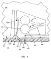
- the optical disk drive (not shown) preferably includes optoelectronic circuitry that is positioned appropriately to emit a beam of light 600 downward through a tray's write protect mechanism 202 after the optical drive extracts the tray from the cartridge 100.
- the circuitry of the optical disk drive determines the write protection status of the disk 110 according to whether the flag 208 blocks the light beam 600. For this reason, the flag 208 preferably comprises an opaque material.
- the optoelectronic circuitry includes a light-emitting element 602 and a light-detecting element 604.
- the light-emitting element 602 comprises a light emitting diode that produces a focused light beam with a small divergence angle.
- Other light-emitting elements may be substituted, such as laser diodes, incandescent light bulbs, or other suitable devices.
- the light-detecting element 604, in an exemplary embodiment, comprises a phototransistor sensitive to the wavelength of light produced by the light-emitting element 602.
- Other light-detecting elements may be substituted, such as photodiodes or other suitable light-detecting devices.
- the elements 602 and 604 are positioned such that the flag 208 blocks the light beam 600 when the finger 204 is in the activated position 214.
- blockage of the light beam 600 signifies that the disk 110 is designated as write protected.
- the elements 602 and 604 may be positioned to block the light beam 600 only when the finger 204 is in the released position 212.
- unblocked passage of the light beam 600 signifies that the disk 110 is write protected.
- the user may designate the released position 212 of the figure 204 to represent the write-protect indication, corresponding to a blocked or unblocked light beam 600, as desired.
Landscapes
- Engineering & Computer Science (AREA)
- Computer Security & Cryptography (AREA)
- Feeding And Guiding Record Carriers (AREA)
Applications Claiming Priority (2)
| Application Number | Priority Date | Filing Date | Title |
|---|---|---|---|
| US08/385,503 US5581540A (en) | 1995-02-08 | 1995-02-08 | Single disk write protection system for multiple-disk cartridge |
| US385503 | 1995-02-08 |
Publications (2)
| Publication Number | Publication Date |
|---|---|
| EP0726573A2 true EP0726573A2 (de) | 1996-08-14 |
| EP0726573A3 EP0726573A3 (de) | 1997-09-24 |
Family
ID=23521655
Family Applications (1)
| Application Number | Title | Priority Date | Filing Date |
|---|---|---|---|
| EP95308921A Withdrawn EP0726573A3 (de) | 1995-02-08 | 1995-12-08 | Datenspeicherplatte und -kassette |
Country Status (3)
| Country | Link |
|---|---|
| US (1) | US5581540A (de) |
| EP (1) | EP0726573A3 (de) |
| JP (1) | JPH08249854A (de) |
Cited By (1)
| Publication number | Priority date | Publication date | Assignee | Title |
|---|---|---|---|---|
| EP1258875A1 (de) * | 2001-05-18 | 2002-11-20 | Deutsche Thomson-Brandt Gmbh | Plattenmagazinsystem |
Families Citing this family (18)
| Publication number | Priority date | Publication date | Assignee | Title |
|---|---|---|---|---|
| US5903538A (en) * | 1994-12-14 | 1999-05-11 | Matsushita Electric Industrial Co., Ltd. | Automatic disk change apparatus and disk tray for the apparatus |
| JP3462318B2 (ja) * | 1995-10-13 | 2003-11-05 | 株式会社東芝 | ディスクカートリッジ装置 |
| JP3426809B2 (ja) * | 1995-10-13 | 2003-07-14 | 株式会社東芝 | ディスクカートリッジ装置 |
| JP3338303B2 (ja) * | 1996-09-25 | 2002-10-28 | アルプス電気株式会社 | ディスクパッケージ |
| JP3308454B2 (ja) * | 1996-09-25 | 2002-07-29 | アルプス電気株式会社 | ディスクパッケージ |
| SG94718A1 (en) | 1998-05-23 | 2003-03-18 | Samsung Electronics Co Ltd | Cartridge for an information recording medium |
| US6529471B1 (en) * | 1998-07-15 | 2003-03-04 | Lg Electronics Inc. | Disc protection casing and drive for receiving the same |
| US6580683B1 (en) | 1999-06-23 | 2003-06-17 | Dataplay, Inc. | Optical recording medium having a master data area and a writeable data area |
| US7227817B1 (en) | 1999-12-07 | 2007-06-05 | Dphi Acquisitions, Inc. | Low profile optical head |
| US7191153B1 (en) | 1999-09-10 | 2007-03-13 | Dphi Acquisitions, Inc. | Content distribution method and apparatus |
| US6631359B1 (en) | 1999-09-10 | 2003-10-07 | Dphi Acquisitions, Inc. | Writeable medium access control using a medium writeable area |
| JP3666646B2 (ja) * | 2000-12-08 | 2005-06-29 | シャープ株式会社 | ディスクカートリッジおよびディスクドライブ |
| US20030123366A1 (en) * | 2001-12-28 | 2003-07-03 | Hung-Chieh Cheng | Optical disc loading tray |
| JP2005276338A (ja) * | 2004-03-25 | 2005-10-06 | Fuji Photo Film Co Ltd | ディスクカートリッジ |
| JP4313739B2 (ja) * | 2004-08-19 | 2009-08-12 | 富士フイルム株式会社 | 記録ディスクカートリッジ |
| TW200614180A (en) * | 2004-10-20 | 2006-05-01 | Lite On It Corp | Optical disc drive and optical disc cassette |
| US7383560B2 (en) * | 2005-01-18 | 2008-06-03 | Imation Corp. | Multi-disk data cartridge |
| US9251346B2 (en) * | 2013-02-27 | 2016-02-02 | Lenovo Enterprise Solutions (Singapore) Pte. Ltd. | Preventing propagation of hardware viruses in a computing system |
Family Cites Families (24)
| Publication number | Priority date | Publication date | Assignee | Title |
|---|---|---|---|---|
| US3662360A (en) * | 1970-06-23 | 1972-05-09 | Digital Information Storage Co | Magnetic information disk equipment |
| US3951264A (en) * | 1974-10-29 | 1976-04-20 | Dynastor, Inc. | Flexible disc cartridge |
| JPS6343643Y2 (de) * | 1980-12-16 | 1988-11-14 | ||
| GB2134306A (en) * | 1983-01-14 | 1984-08-08 | Emi Ltd | Improvements relating to video disc containers |
| JPS59168876U (ja) * | 1983-04-22 | 1984-11-12 | 富士写真フイルム株式会社 | 磁気デイスクカ−トリツジ |
| US4564871A (en) * | 1983-12-27 | 1986-01-14 | Minnesota Mining And Manufacturing Company | Automatic record-lockout mechanism |
| NL8401672A (nl) * | 1984-05-25 | 1985-12-16 | Philips Nv | Houder voor een starre informatieplaat alsmede systeem omvattende een dergelijke houder en een daarmee samenwerkend laadmechanisme. |
| JPS6168186A (ja) * | 1984-09-08 | 1986-04-08 | 井関農機株式会社 | 重量選別装置 |
| JPS6168767A (ja) * | 1984-09-12 | 1986-04-09 | Fujitsu Ltd | 磁気テ−プのデ−タ保護方式 |
| FR2575857B1 (fr) * | 1984-11-29 | 1995-03-03 | Canon Kk | Appareil de stockage optique d'informations |
| JPH0634324B2 (ja) * | 1985-03-08 | 1994-05-02 | パイオニア株式会社 | デイスクの収納容器 |
| DE3645040C2 (de) * | 1985-03-08 | 1993-04-29 | Pioneer Electronic Corp., Tokio/Tokyo, Jp | |
| US4800554A (en) * | 1986-10-01 | 1989-01-24 | Victor Company Of Japan, Limited | Disk magazine |
| US4908817A (en) * | 1986-11-14 | 1990-03-13 | Opticord, Inc. | Cartridge for optical data discs |
| DE3715164A1 (de) * | 1987-05-07 | 1988-11-24 | Thomson Brandt Gmbh | Cd-plattenwechsler |
| US4819114A (en) * | 1987-12-16 | 1989-04-04 | Eastman Kodak Company | Write-protected data storage disk assembly |
| JPH01204250A (ja) * | 1988-02-09 | 1989-08-16 | Hiroyoshi Muraoka | 再録画・誤消去防止装置 |
| JPH01251367A (ja) * | 1988-03-31 | 1989-10-06 | Toshiba Corp | ディスクプレーヤシステム |
| KR930003195B1 (ko) * | 1988-08-10 | 1993-04-23 | 마쯔시다덴기산교 가부시기가이샤 | 디스크 매거진 |
| JPH0292887U (de) * | 1988-12-29 | 1990-07-24 | ||
| US5231552A (en) * | 1990-06-29 | 1993-07-27 | Digital Equipment Corporation | Magazine and receiver for media cartridge loader |
| US5371644A (en) * | 1991-08-12 | 1994-12-06 | Storage Technology Corporation | Self identifying universal data storage element with human intelligible write protect mechanism |
| JP2576844Y2 (ja) * | 1991-11-01 | 1998-07-16 | ティーディーケイ株式会社 | ディスクカートリッジ |
| US5903538A (en) * | 1994-12-14 | 1999-05-11 | Matsushita Electric Industrial Co., Ltd. | Automatic disk change apparatus and disk tray for the apparatus |
-
1995
- 1995-02-08 US US08/385,503 patent/US5581540A/en not_active Expired - Fee Related
- 1995-12-08 EP EP95308921A patent/EP0726573A3/de not_active Withdrawn
-
1996
- 1996-02-05 JP JP8018860A patent/JPH08249854A/ja active Pending
Non-Patent Citations (1)
| Title |
|---|
| None |
Cited By (1)
| Publication number | Priority date | Publication date | Assignee | Title |
|---|---|---|---|---|
| EP1258875A1 (de) * | 2001-05-18 | 2002-11-20 | Deutsche Thomson-Brandt Gmbh | Plattenmagazinsystem |
Also Published As
| Publication number | Publication date |
|---|---|
| JPH08249854A (ja) | 1996-09-27 |
| US5581540A (en) | 1996-12-03 |
| EP0726573A3 (de) | 1997-09-24 |
Similar Documents
| Publication | Publication Date | Title |
|---|---|---|
| US5581540A (en) | Single disk write protection system for multiple-disk cartridge | |
| US4916567A (en) | Storage cassette for a disc-shaped information carrier | |
| US5058100A (en) | Disc magazine | |
| US4752234A (en) | Contacting apparatus for a chip-card | |
| KR20020031155A (ko) | 판형 광 데이터 캐리어 | |
| US6160679A (en) | Recording medium device for use with a tape cartridge having an auxiliary memory viewable through a cartridge discrimination opening | |
| HK71590A (en) | Magnetic tape cassette case | |
| GB2090226A (en) | Magnetic recording cassettes having an erroneous erasure preventing device | |
| EP0174111A2 (de) | Schliessmechanismus für eine Kassette | |
| HU216196B (hu) | Diszk cartridge | |
| US5628399A (en) | Indicating CD case insert | |
| US5196978A (en) | Cartridge case | |
| JP2001500301A (ja) | メモリカード及びそれに用いるリーダ | |
| US6031676A (en) | System for sensing a tape cartridge | |
| EP1130593A2 (de) | Plattenkassette mit Falscheinlegungverhinderungsunterscheidung | |
| JPH04507053A (ja) | カード等の平板状物のための容器 | |
| GB2098380A (en) | Apparatus for reproducing signals recorded on disk | |
| EP0793231B1 (de) | Bandkassette | |
| US4660105A (en) | Cassette recording or non-recording indicating mechanism | |
| US6270030B1 (en) | System for controlling compatibility of tape cartridges having the same form factor | |
| KR970067167A (ko) | 광디스크 및 디스크카트리지 | |
| WO1999053495A1 (en) | Tape cartridge | |
| US5617396A (en) | Disk tray having a system for retaining a disk at a position therein | |
| JP3601741B2 (ja) | カートリッジ収納ケース | |
| JP4455641B2 (ja) | カード用コネクタ装置 |
Legal Events
| Date | Code | Title | Description |
|---|---|---|---|
| PUAI | Public reference made under article 153(3) epc to a published international application that has entered the european phase |
Free format text: ORIGINAL CODE: 0009012 |
|
| AK | Designated contracting states |
Kind code of ref document: A2 Designated state(s): DE FR GB |
|
| 17P | Request for examination filed |
Effective date: 19970120 |
|
| PUAL | Search report despatched |
Free format text: ORIGINAL CODE: 0009013 |
|
| AK | Designated contracting states |
Kind code of ref document: A3 Designated state(s): DE FR GB |
|
| STAA | Information on the status of an ep patent application or granted ep patent |
Free format text: STATUS: THE APPLICATION HAS BEEN WITHDRAWN |
|
| 18W | Application withdrawn |
Withdrawal date: 19980220 |