EP0726668A1 - Terminal de transmission - Google Patents
Terminal de transmission Download PDFInfo
- Publication number
- EP0726668A1 EP0726668A1 EP95930026A EP95930026A EP0726668A1 EP 0726668 A1 EP0726668 A1 EP 0726668A1 EP 95930026 A EP95930026 A EP 95930026A EP 95930026 A EP95930026 A EP 95930026A EP 0726668 A1 EP0726668 A1 EP 0726668A1
- Authority
- EP
- European Patent Office
- Prior art keywords
- main shell
- communication terminal
- terminal apparatus
- muting
- transmitter
- Prior art date
- Legal status (The legal status is an assumption and is not a legal conclusion. Google has not performed a legal analysis and makes no representation as to the accuracy of the status listed.)
- Withdrawn
Links
Images








Classifications
-
- H—ELECTRICITY
- H04—ELECTRIC COMMUNICATION TECHNIQUE
- H04M—TELEPHONIC COMMUNICATION
- H04M1/00—Substation equipment, e.g. for use by subscribers
- H04M1/02—Constructional features of telephone sets
- H04M1/03—Constructional features of telephone transmitters or receivers, e.g. telephone hand-sets
-
- H—ELECTRICITY
- H04—ELECTRIC COMMUNICATION TECHNIQUE
- H04M—TELEPHONIC COMMUNICATION
- H04M1/00—Substation equipment, e.g. for use by subscribers
- H04M1/02—Constructional features of telephone sets
- H04M1/0202—Portable telephone sets, e.g. cordless phones, mobile phones or bar type handsets
- H04M1/0206—Portable telephones comprising a plurality of mechanically joined movable body parts, e.g. hinged housings
- H04M1/0241—Portable telephones comprising a plurality of mechanically joined movable body parts, e.g. hinged housings using relative motion of the body parts to change the operational status of the telephone set, e.g. switching on/off, answering incoming call
- H04M1/0245—Portable telephones comprising a plurality of mechanically joined movable body parts, e.g. hinged housings using relative motion of the body parts to change the operational status of the telephone set, e.g. switching on/off, answering incoming call using open/close detection
-
- H—ELECTRICITY
- H04—ELECTRIC COMMUNICATION TECHNIQUE
- H04M—TELEPHONIC COMMUNICATION
- H04M1/00—Substation equipment, e.g. for use by subscribers
- H04M1/26—Devices for calling a subscriber
- H04M1/27—Devices whereby a plurality of signals may be stored simultaneously
- H04M1/274—Devices whereby a plurality of signals may be stored simultaneously with provision for storing more than one subscriber number at a time, e.g. using toothed disc
- H04M1/2745—Devices whereby a plurality of signals may be stored simultaneously with provision for storing more than one subscriber number at a time, e.g. using toothed disc using static electronic memories, e.g. chips
- H04M1/27453—Directories allowing storage of additional subscriber data, e.g. metadata
- H04M1/2746—Sorting, e.g. according to history or frequency of use
-
- H—ELECTRICITY
- H04—ELECTRIC COMMUNICATION TECHNIQUE
- H04M—TELEPHONIC COMMUNICATION
- H04M1/00—Substation equipment, e.g. for use by subscribers
- H04M1/26—Devices for calling a subscriber
- H04M1/27—Devices whereby a plurality of signals may be stored simultaneously
- H04M1/274—Devices whereby a plurality of signals may be stored simultaneously with provision for storing more than one subscriber number at a time, e.g. using toothed disc
- H04M1/2745—Devices whereby a plurality of signals may be stored simultaneously with provision for storing more than one subscriber number at a time, e.g. using toothed disc using static electronic memories, e.g. chips
- H04M1/27467—Methods of retrieving data
- H04M1/2747—Scrolling on a display
-
- H—ELECTRICITY
- H04—ELECTRIC COMMUNICATION TECHNIQUE
- H04M—TELEPHONIC COMMUNICATION
- H04M1/00—Substation equipment, e.g. for use by subscribers
- H04M1/72—Mobile telephones; Cordless telephones, i.e. devices for establishing wireless links to base stations without route selection
- H04M1/724—User interfaces specially adapted for cordless or mobile telephones
-
- H—ELECTRICITY
- H04—ELECTRIC COMMUNICATION TECHNIQUE
- H04M—TELEPHONIC COMMUNICATION
- H04M1/00—Substation equipment, e.g. for use by subscribers
- H04M1/02—Constructional features of telephone sets
- H04M1/0202—Portable telephone sets, e.g. cordless phones, mobile phones or bar type handsets
- H04M1/0206—Portable telephones comprising a plurality of mechanically joined movable body parts, e.g. hinged housings
- H04M1/0208—Portable telephones comprising a plurality of mechanically joined movable body parts, e.g. hinged housings characterized by the relative motions of the body parts
- H04M1/0214—Foldable telephones, i.e. with body parts pivoting to an open position around an axis parallel to the plane they define in closed position
Definitions
- Such a multi-function communication terminal apparatus offers auto-dial or speed call for selecting one from a plurality of telephone numbers stored in a memory installed in the main shell and dialing it automatically, as well as registering any name and number to a list of telephone numbers in the memory.
- the communication terminal apparatus for use with a portable radio phone system is of a hand-held type which is essentially required for having minimum size and weight.
- each of the conventional terminal apparatuses is equipped with a sheet type of dial keys, a highly advanced battery(s), and a state-of-art integrated circuit which all are light weighted.
- a communication terminal apparatus comprises: a speech input means arranged movable from a position adjacent to a main shell to a position distanced from the main shell for calling; a speech output means for reproducing a received signal as an audible sound; a detector means for detecting the position of the speech input means; and a controller means responsive to a detection signal from the detector means for controlling the input and output of a voice signal.
- the controller means includes a muting means responsive to the detection signal from the detector means for muting a signal output of the speech input or output means.
- the muting means performs a muting action when the detection signal from the detector means indicates that the speech input means is located at the position adjacent to the main shell.
- the communication terminal apparatus of the present invention further comprises a means for generating a hold signal in response to the muting action of the muting means.
- the hold signal produced by the generating means is transmitted to a calling party at the other end of the line.
- the speech input means of the communication terminal apparatus comprises an arm pivotably mounted to the main shell for movement between an on-hook position adjacent to the main shell and a call position distanced from the same, and a microphone unit mounted to the arm.
- the detector means comprises a detection target made of a magnet and mounted to either the arm of the speech input means or the main shell, and a detector composed of a Hall device and mounted to the other.
- Another communication terminal apparatus comprises: a microphone module arranged movable between an on-hook position adjacent to a main shell and a call position distanced from the main shell; a transmitter/receiver means for modulating and transmitting an output signal from the microphone module, and modulating and reproducing an input signal; a speaker module for emitting an audible sound corresponding to the demodulated input signal from the transmitter/receiver means; a detector means for detecting the position of the microphone module; and a controller means responsive to a detection signal from the detector means for controlling the input and output of the voice signals.
- the controller means includes a muting means for muting the output signal of the microphone module upon the detector detecting that the microphone module is located at the on-hook position.
- the communication terminal apparatus further comprises a means for generating in response to the muting action of the muting means a hold signal which is then transmitted to the transmitter/receiver means and forwarded from the same.
- Fig.1 is a partially broken perspective view showing a transmitter turned open from a main shell to a call position.
- Fig.2 is a plan view of the transmitter held on the main shell.
- Fig.3 is a block diagram of a circuitry arrangement installed in a communication terminal apparatus.
- Fig.4 is a schematic diagram explaining a small font.
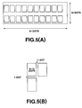
- Fig.5 is a schematic diagram explaining a large font.
- Fig.6 is a series of illustrations explaining shift of one font to another due to the size of input characters.
- Fig.7 is a series of illustrations explaining shift of a display screen with a menu key.
- Fig.8 is a series of illustrations explaining shift of a display screen with a clear key.
- Fig.10 is a plan view showing the construction of a rotary encoder.
- Fig.11 is a waveform diagram showing signal waveforms from the rotary encoder.
- Fig.12 is a series of illustrations explaining shift of a display screen with the rotary key.
- Fig.14 is a series of illustrations showing steps of calling procedure.
- Fig.16 is a series of illustrations showing steps of calling procedure with a telephone number list.
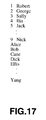
- Fig.17 is a diagram showing a row of character names in the telephone number list.
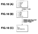
- Fig.18 is a series of illustrations showing steps of retrieving a data with numeral keys.
- Fig.19 is a series of illustrations explaining return from a detailed data screen to a list screen.
- Fig.20 is a series of illustrations showing a procedure of registering a name in the telephone number list screen.
- Fig.21 is a series of illustrations showing another procedure of registering a name in the telephone number list screen.
- Fig.25 is a series of illustrations showing mode setting screens.
- Fig.27 is a series of illustrations showing a detailed data screen for volume setting.
- the side of the main shell 1 which acts as an on-hook station for the transmitter 2 and will be explained later in more details is substantially flattened at surface extending lengthwisely.
- a telescopic antenna 8 is mounted to a top side of the main shell 1 which is at a right angle to the transmitter 2 mounting side.
- An arcuately projecting, bulged facet 5 is provided on the upper end of a lengthwisely extending side of the main shell 1 opposite to the transmitter mounting side, as shown in Figs.1 and 2.
- a recording key 10i which is a member of the input device 10 is mounted on the top side of the main shell 1 to be opposite to the antenna 8.
- the input device 10 further includes a rotary key 10j mounted beneath the bulged facet 5 on the other side of the main shell 1.
- the mounting of the transmitter 2 to the on-hook side of the main shell 1 is by means of a pivotal support 14 secured to the lower end of the on-hook side of the main shell 1 for pivotal movement of the distal end of the arm 12.
- the transmitter 2 turns about the pivotal support 14 in opposite directions denoted by the arrows A and B of Fig.1.
- the transmitter 2 can move from its on-hook position on the on-hook side of the main shell 1 where it rests lengthwisely as shown in Fig.2 to its call position where its microphone 13 is distanced from the main shell 1 as shown in Fig.1 for making or receiving a call.
- a holder 15 is mounted as a member of the on-hook station on the on-hook side of the main shell 1 for holding the transmitter 2 which has been turned to the on-hook position, extending outwardly from the lower half 6 of the main shell 1.
- the holder 15 has an L shape in cross section so that it can accept the transmitter 2 through its opening at the front of the main shell 1 and detachably retain it at the on-hook position. As its extended arm 12 is held in the holder 15, the transmitter 2 can be protected at the on-hook position.
- a detector 21 is provided between the main shell 1 and the transmitter 2 for detecting whether the transmitter 2 is at the on-hook position on the main shell 1 or at the call position with its microphone unit 13 distanced from the main shell 1.
- the detector 21 comprises a Hall device 22 mounted to the on-hook side of the main shell 1 for facing the transmitter 2 at the on-hook position, and a magnetic member 23 mounted to the main shell 1 side of the transmitter 2 for acting as an objective to be detected by the Hall device 22 when the transmitter 2 is at its on-hook position. More particularly, the Hall device 22 is installed in the main shell 1 and exposed through an aperture 24 provided in the on-hook side of the main shell 1 to the outside.
- the magnetic member 23 is made of a magnetic material or sheet and bonded by e.g. an adhesive to the main shell 1 side of the arm 12 of the transmitter 2.
- a display 25 e.g. an LCD, is provided on substantially a center region of the front side of the main shell 1 between the speaker facet 9 of the speaker 7 and the key control 10, as shown in Figs.1 and 2.
- the main shell 1 contains a central processing unit (CPU) 31 mounted on the printed circuit board for serving as a controller.
- CPU central processing unit
- the CPU 31 drives the display 25 through a display driver circuit 32 for displaying a desired font of information entered from the key control 10, as shown in Fig.3.
- the CPU 31 is also loaded with the prescribed detection signal of the detector 21 indicating that the transmitter 2 is held in the holder 15 of the main shell 1 or that the same is turned away with its microphone unit 13 distanced from the main shell 1.
- the detection signal is used as a control signal for controlling the input control mechanism 10 and a transmitter/receiver circuit 35.
- Programs stored in a ROM and data read from a RAM 34 are then supplied to the CPU 31.
- the CPU 31 performs an arithmetic operation according to the programs stored in the ROM 33 and/or data saved in the RAM 34.
- the CPU 31 controls the action of the transmitter/receiver circuit 35 mounted on the printed circuit board of the main shell 1.
- the DSP 37 also includes an amplifier circuit for amplifying the voice signals from the microphone unit 13 and the modulator/demodulator circuit 36,
- the DSP 37 is further equipped with a hold signal generator circuit responsive to the control signal from the CPU 31 for generating a hold signal when the communication terminal apparatus is busy.
- the hold signal generated in the hold signal generator circuit of the DSP 37 is then modulated by the modulator/demodulator circuit 36 and released through the antenna 8.
- the DSP 37 serves as a means for generating the hold signal.
- the CPU 31 is connected to a card socket 36 to which a subscriber identity module (SIM) card 37 is inserted. Data of a subscriber is read from the SIM card 37 and used by the CPU 31 for performing a routine mode of control in the terminal apparatus.
- SIM subscriber identity module
- the display 25 of the embodiment is an LCD comprising a matrix of pixels, 32 rows by 97 columns, for display of two different fonts: a small font consisting of 5 dots high by 7 dots wide as shown in Figs.4(A) and 4(B) and a large font consisting of 15 dots high by 8 dots wide as shown in Figs.5(A) and 5(B).
- a small font consisting of 5 dots high by 7 dots wide as shown in Figs.4(A) and 4(B)
- a large font consisting of 15 dots high by 8 dots wide as shown in Figs.5(A) and 5(B).
- the large font is for displaying characters entered by the user while the small font is for displaying messages attributed to the terminal apparatus. It is however designed that if the total number of characters entered by the user exceeds a given number (preferably 20), its display is systematically shifted from the small font to the large font.
- Fig.6 illustrates an example of consecutive display screens appearing on the display 25.
- the display starts with showing beneath a message of small font characters, "input dial No", a group of large font characters entered by the user until the number of the input characters exceeds 10. If more than 10 of the large font characters are entered, 10 of them move to the upper row and eliminate the small font message and then, the eleventh and higher large font characters appear at the lower row.
- the two, upper and lower, rows in the display 25 have been filled with 20 of the large font characters, all the large font characters are replaced by their corresponding small font characters at once.
- the large font allows ease of viewing the display before it is replaced by the small font, whereby error reading or entering will be minimized. Even if a considerable number of small font characters are entered for bulky information, they are viewed on one screen of the display 25 and can be acknowledged with much ease.
- the ten numeral keys 10b located on the front side of the main shell 1 are provided for entry of numbers and as well as alphabetical letters.
- the alphabetical letters are allocated to the eight, "2" to “9", keys excluding the "0" and “1” keys. For instance, a, b, and c are assigned to the “2" key and d, e, and f are assigned to the "3" key, and so on.
- the menu key 10g is used for switching between a start screen and a menu screen on the display 25. For example, while the start screen appears on the display 25 as shown in Fig.7(A), pressing of the menu key 10g shifts from the start screen to the menu screen shown in Fig.7(B). Then, a scroll movement, which will be described later, allows the display 25 to access a screen shown in Fig.7(C) like as turning to a new page. When the menu key 10g is pressed with the menu screen appearing, the display 25 instantly shifts to the start screen.
- the clear key 10h functions returning to the preceding screen or page as shown in Fig.8.
- menu key 10g Another function of the menu key 10g is to disable the key locking which inhibits the entry action of the main keys 10a to 10h, record key 10i, and rotary key 10j of the key control 10.
- the rotary shaft O is fixedly mounted to the slide plate so that when the rotary key 10j is pressed in the F direction, its disk assembly or rotary encoder moves inwardly together with the slide plate to turn on the switch SW.
- the on and off action of the switch SW is detected by the CPU 31 which in turn judges whether or not the rotary key 10j is clicked down.
- the rotary encoder movable along with the slide plate comprises, as shown in Fig.10, two disks 61 and 62.
- the disk 61 is a rotating member mounted to the upper side of the other disk 62, which is fixedly mounted to the slide plate, so that the disk 61 can rotate relative to the disk 62.
- the rotatable disk 61 has two, inner and outer, contact electrodes 63 mounted to one side thereof.
- the contact electrodes 63 are designed to run directly along 20 pairs of stationary electrodes 64 mounted to the perimeter of the disk 62.
- Each pair of the inner and outer stationary electrodes 64 on the disk 62 are spaced radially and dislocated from each other circumferentially.
- the pressing of the rotary key 10j for a predetermined period of time starts a call.
- the magnitude of a received sound can be controlled by rotating the rotary key 10j. If the rotary key 10j is clicked during the call, a muting function sets out to kill the received sound temporarily.
- Fig.12 is a flow chart showing common steps of controlling with the rotary key 10j.
- the procedure starts with switching on the power key 10a for energization of the terminal apparatus and entering the PIN data of a user.
- a corresponding set of the keys 10a to 10f and 10h to 10j are actuated at Step S101, it is examined at Step S102 whether or not the transmitter 2 is at its call position as having been released from the holder 15 on the on-hook side of the main shell 1. If the detector 21 produces a yes detection signal indicating that transmitter 2 has been turned about the pivot support 14 in the A direction of Fig.1 and is at its call position off the main shell 1, the procedure goes to Step S103 where the CPU 31 enables the operating keys 10a to 10j. As desired ones of the keys 10a to 10j are actuated by the user, their functions are executed.
- pressing the menu key 10g changes the display 25 from the start screen to the menu screen.
- a call to a desired telephone number can be made.
- an action of registering and editing telephone numbers on the telephone number list, described later, may be carried out using the numeral keys 10b.
- Step S102 When a no detection signal is released from the detector 21 at Step S102 which indicates that the transmitter 2 has been turned about the pivot support 14 in the B direction of Fig.1 and is at its on-hook position in the holder 15 on the on-hook side of the main shell 1, the procedure moves to Step S104. It is then examined at Step S104 whether the menu key 10g is actuated or not. If not, the start screen is maintained and shown on the display 25. When it is judged that the menu key 10g is actuated, the procedure advances to Step S105 where the CPU 31 commands display of the menu screen on the display 25.
- the CPU 31 examines any key action during a period of time after the display of the menu screen at Step S106. If it is judged by the CPU 31 at Step S106 that non of the keys 10a to 10j is actuated for the period, the procedure goes to Step S107 where the CPU 31 disables the keys 10a and 10j and automatically shifts the display 25 from the menu screen to the start screen.
- Step S108 When one or more of the keys 10a to 10j are actuated during the period at Step S108, the procedure goes to Step S109 where it is examined by the CPU 31 whether the menu key 10g is actuated or not. If it is judged that the menu key 10g is actuated again, the CPU 31 closes the menu screen at Step S110 and displays the start screen on the display 25 inhibiting the action of the keys 10a to 10f and 10h and 10j while enabling the menu key 10g.
- Step S109 If it is judged by the CPU 31 at Step S109 that any other of the keys 10a to 10f and 10h to 10j than the menu key 10g is actuated, the procedure moves to Step S111.
- the CPU 31 allows at Step S111 the function of any of the keys 10a to 10f and 10h to 10j to be enabled. For instance, if the rotary key 10j is actuated, its function of making a call can be implemented.
- the communication terminal apparatus of the present invention has five modes of transmission control which include mainly a mode of using the telephone number list, a mode of redialing, a mode of entering a telephone number directly, and a mode of using a one-touch speed dialing.
- a call using the telephone number list starts with releasing the transmitter 2 from its on-hook position on the main shell 1 to locate its microphone 13 away from the main shell 1, or holding an external microphone connected to the main shell 1, or setting a hand-free kit connected to the main shell 1. Then, clicking of the rotary key 10j shifts the display 25 from the start screen such as shown in Fig.16(A) to the telephone number list screen such as shown in Fig.16(B).
- the telephone number list comprises, as shown in Fig.17, a frequent use column containing a group of names and their telephone numbers labeled 1 to 9 which may be used at higher frequencies, and an alphabetical order column containing all the registered names and their telephone numbers in an alphabetical order (including the names from 1 to 9 and their telephone numbers in the frequent use column).
- the cursor K Upon the display 25 shifting to and showing the telephone number list, the cursor K points out the first of options or an address number 1 of the list. As the rotary key 10j is turned downwardly in the D direction of Fig.10, the cursor K moves from 1 to 2, 3,.... If the rotary key 10j is rotated upwardly in the C direction, the cursor K travels from bottom to Z, Y, X....
- the cursor K is moved to a desired name by hitting a corresponding one of the "1" to “9” numeral keys 10b. For example, when the "2" key 10b is pressed, the cursor K moves to the letter A on the screen. When the "3" key 10b is pressed, the cursor K moves to the letter D. If no name starting from D is found, the cursor K points out a name starting from E. If E is not found, the cursor K goes to a name starting from the next letter.
- the rotary key 10j is turned upwardly or downwardly in the C or D direction of Fig.10.
- the upward turning of the rotary key 10j in the C direction with the current screen such as shown in Fig.19(B) the display turns back to the preceding screen.
- the cursor K is also shifted from the current option of the previous option. More specifically, the cursor K moves from the address number 5 for Ellis to the address number 4 for John in Fig.19(C).
- the SEND key 10e may be used with the display shown in Fig.16(D). As the call is made when the detailed data screen has been displayed in the above case, it may be commenced directly from the list screen according to a function of the embodiment. For example, pressing the SEND key 10e with the display shown in Fig.16(C) can start a call to the person pointed with the cursor K. Also, pressing a desired one of the numeral keys 10b for one second produces a direct call.
- a redialing list opens when the SEND key 10e is pressed on the start screen. Hitting the SEND key 10e shifts the display from the start screen shown in Fig.14(A) to the redialing list shown in Fig.14(G) where a record of calls is viewed indicating transmitted telephone numbers and names. Selecting and calling a desired telephone number or name can be made directly from the redialing list by the same manner as with the prescribed list screen.
- the communication terminal apparatus of the present invention may also have a function to indicate a time record of the previous call, as shown in Fig.14(H) where the time record is 4:25, and a duration of the current call, as shown in Fig.15(J) where the duration is 0:00:55.
- a call is made by directly entering the telephone number of a receiver with the start screen shown in Fig.14(A).
- the display has changed from the start screen shown in Fig.14(A) to a screen shown in Fig.14(K), the telephone number is viewed in the large font.
- the telephone number entered by the user and displayed is examined and if correct, the SEND key 10e is pressed.
- the screen shown is flashed at intervals such as shown in Fig.15(L) starting transmission of a signal.
- Two modes are available in the procedure: pressing a corresponding one of the numeral keys 10b for a predetermined period of time and using a combination of the # key 10c and the numeral key 10b.
- the former is shown in Figs.15(O) to 15(P) where the numeral key 10b only is used.
- the display 25 is shifted to a corresponding detailed data screen shown in Fig.14(C) starting a call.
- Figs.14(Q), 15(S), and 15(S) where both the numeral key 10b and the # key 10c are used.
- the display 25 is shifted to a corresponding detailed data screen shown in Fig.14(Q). Then, the call is started by pressing the SEND key 10e.
- the communication terminal apparatus drives the detector mechanism 21 to examine whether the transmitter 2 is at the on-hook position on the main shell 1 or its microphone unit 13 is kept at the call position distanced from the main shell 1.
- the detection signal of the detector mechanism 21 is used for controlling the output of a voice signal from the microphone 13 or the input to the speaker 7.
- the Hall device 22 of the detector mechanism 21 senses an intensity of magnetic flux from the magnetic material 23 of the transmitter 2 thus yielding a detection signal indicative of the presence of the transmitter 2 at the on-hook position.
- the detection signal is transmitted to the CPU 31 which in turn actuates the DSP 37 in the transmitter/receiver circuit 35. Accordingly, the DSP 37 controls the level of the voice signal of the microphone unit 13 to mute an input to the modulator/demodulator circuit 36.
- the DSP 37 also serves a means for muting the voice output from the transmitter 2 and the voice input to the speaker 7.
- the hold signal is fed to the modulator/demodulator circuit 36 for modulation and sent out through the antenna 8.
- the hold signal is generated and transmitted upon the voice output of the microphone unit 13 being muted so that it can inform the calling party that the line remains connected.
- the CPU 31 in responsive to the detection signal from the detector mechanism 21 indicative of the presence of the transmitter 2 at its on-hook position can instruct the amplifier circuit of the DSP 37, which amplifies the voice input to the speaker 7, to mute an audible sound from the speaker 7.
- any of the operating keys 10a to 10j of the input control mechanism 10 is designated as a dedicated selector switch.
- the transmitter 2 When the transmitter 2 is turned about the pivot support 14 in the direction A shown in Fig.1 to the call position with the microphone 13 mounted to the distal end of its arm 12 spaced away from the main shell 1 during the communication but with either the voice output from the microphone 13 or the voice input to the speaker 7 being muted, its magnetic material 23 departs from the Hall device 22 which becomes disable to detect the magnetic flux of the magnetic material 23. Accordingly, the detector mechanism 21 produces and transmits a detection signal indicative of the removal of the transmitter 2 from the main shell 1. The absence detection signal is then fed to the CPU 31 which in turn cancels the muting of the voice output from the microphone unit 13 or the voice input to the speaker 7. As the result, the voice signal from the microphone unit 13 is further transmitted through the antenna 8 and the voice input to the speaker 7 is converted to an audible sound.
- the communication terminal apparatus of the present invention is provided with a muting function for muting the voice output from the microphone unit 13 or the voice input to the speaker 7 upon the transmitter 2 being turned back to its on-hook position.
- the procedure starts with pressing the menu key 10g to open the menu screen and selecting an option of Telbook Edit.
- a first manner consists of selecting an option of New Register and entering a telephone number to be registered.
- the cursor K is moved to New Register by the user operating the rotary key 10j and clicked (See Fig.20(B)).
- the display turns to a screen shown in Fig.20(C) and entry of a desired name to be registered is demanded.
- a set of the numeral keys 10b are pressed, corresponding alphabetical letters of the large font appear in the screen. If the letters in the screen is correct, they are registered by clicking the rotary key 10j and the display moves to a screen for registering a telephone number.
- the telephone numbers are then entered and registered by controlling the rotary key 10j. As the result, the name and telephone number are newly loaded in a vacant row of the telephone number list as shown in Fig.20(D).
- a second manner consists of selecting an unused address number and registering a desired name for the number.
- the cursor K is first moved to the unused address number as shown in Figs.21(A) and 21(B) where the number is 7. Then, clicking of the rotary key 10j causes the display 25 to demand entry of the name.
- the procedure of editing starts with locating the cursor K to a name to be edited and clicking the rotary key 10j.
- the editing mode screen appears upon accessing the name or choice which has been registered.
- the editing mode screen has several options including Edit, Delete, and Swap while showing the name accessed. The user can select any of the options on the screen using the rotary key 10j.
- Delete when Delete is selected, the display 25 turns to a screen shown in Fig.23(D) where it is questioned if you are sure to delete. If yes is selected, the action of Delete is done.
- the menu mode displayed on the display 25 by hitting the menu key 10g of the key control 10 will be explained.
- the menu mode comprises a group of main screens and their subscreens which can be retrieved by operating the rotary key 10j.
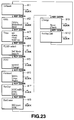
- Fig.23 illustrates the main screens, W1 to W10, installed in the communication terminal apparatus of the embodiment.
- the menu subscreens are shown in Figs.24 t 27.
- the first main screen W1 has two options, Telbook for accessing to the telephone number list and Mode for setting a mode.
- Telbook provides registering a new dial number list and editing the telephone number list.
- Mode When Mode is selected, the display changes to a Mode screen shown in Fig.24(A) where several setting options are displayed for optimum environment.
- the screen of Fig.24(A) shows four mode options of Normal, Pocket, Silent, and Driving.
- a ringer In Pocket mode, for example, a ringer is switched on for maximum ringing and the key lock is turned on. This allows the user to hardly miss a ringing sound under noisy conditions and to avoid unwanted key actions.
- Silence mode causes the ringer to switch off and allows the display 25 to flash indicating reception of a call. For example, the user can acknowledge an incoming call without disturbing people around in a crowded commute train. Also, this mode provides an extra function of automatically disconnecting a call when no answer is made.
- the second main screen W2 is designed for setting a short message (SMS) and displays three options: Delete, Make Send, and Read.
- SMS short message
- the display moves to subscreens for writing a new message to be transmitted, using an original pattern message, and retrieving a recorded message which has been transmitted or received.
- Selection of Read is followed by a subscreen for storing or deleting a read message, or replying by phone or with a short message.
- the third main screen W3 is provided for setting a time (Time) and has four options: Set for setting a time, Alarm for setting an alarm time, Sleep for setting an OFF time, and Wake up for setting an ON time.
- the fourth main screen W4 is designed for setting a public lie-dit mobile network (PLMN) and has two options: Sel Mode (selection mode) and Search.
- PLMN public lie-dit mobile network
- Sel Mode selection mode
- Search Search
- the former is selected for setting a network by a manual mode or an automatic mode.
- the latter is used for automatically searching and displaying an available network.
- the fifth main screen W5 is provided for setting a personal identification number (PIN) and displays two options; Control and Change.
- PIN personal identification number
- the former is used for determining entry of an ID number as an initial requirement to limit the use to eligible personals.
- the latter is selected for changing an ID number.
- the sixth main screen W6 is provided for setting a forwarding action (Forward) and has three options: Intrro (interrogation), Erase, and Regist (registration). Intrro is selected for interrogating a forwarding service to the network. Erase and Regist are used for erasing and registering a forwarding target respectively.
- the seventh main screen W7 is designed for setting a barring of outgoing calls (BarOut) and has three options: BOIC-exHC (barring of outgoing international calls except those directed to the HPLMN country), BOIC (barring of outgoing international calls), and BAOC (barring of all outgoing calls). Any option will be selected for determining a desired mode of the setting.
- the eighth main screen W8 is provided for setting a barring of incoming calls (BarCome) and has two options: BICroam (barring of incoming calls in roaming except those from the PLMN country) and BAIC (barring of all incoming calls). Either option will be selected for determining a desired mode of the setting.
- the ninth main screen W9 is provided for setting a charge data and displays two options: Reset and Check. The former is selected for resetting the charge data while the latter is used for displaying the charge data.
- the tenth main screen W10 is designed for accessing a setting list (Setting List) and contains five subscreens shown in Fig.25. Through scrolling down, the tenth screen is shifted to the first main screen W1.
- the five subscreens of the tenth menu W10 are now explained starting with a first subscreen SW1 which displays four options: Call ID Present, Language Select, Any Key Answer, and 1 Min Beep.
- Call ID Present is used for forwarding the telephone number of the transmitter to a receiver.
- Any Key Answer is for allowing any key to start an answer.
- 1 Min Beep is selected for emitting a beep sound at every one minute to indicate consumption of time.
- a second subscreen SW2 contains four option: Ringer Select, LowSignal Warn, LowBattery Warn, and Ringer Volume.
- Ringer Select When Ringer Select is clicked, three ringer options are displayed as shown in Fig.26 and from which one is selected. Ringer Volume allows selection of a desired volume from three different levels shown in Fig.26.
- a third subscreen SW3 has four options: LCD Density for determining the intensity of light on LCD, Change PIN2 for modifying a personal ID number, AutoVolume CTRL for increasing a sound automatically when background noise is high, and Noise Reduction.
- a fourth subscreen SW4 on the display 25 displays four options: Clock Display for indicating a time, SMS ServCenter for changing the address of a service center, SMS Enquiry for indicating the receipt of a short message at a receiver, and SMS Telmatic for sending a short message to a facsimile.
- a fifth subscreen SW5 provides three options: SMS Class for weighting a short message depending on its significance, Change Password for modifying a password which controls calls with its extra service allowance, and Charge ACMM for limiting the number of calls to an upper limit.
- the display shifts from the current screen to the preceding screen with the cursor K appearing at the top of options. Also, if the cursor K is moved downward from the bottom of options in the current screen, the display shifts from the current screen to the succeeding screen with the cursor K locating at the bottom of options.
- This scrolling action allows the cursor K to be quickly moved from one screen to another.
- a turnable control key may be used of which movement is limited to a given angle. It is also possible to employ a slidable control lever or a track ball with a click control. A slide switch with a click control may be utilized. Any of them is applicable to the embodiment thus providing a communication terminal apparatus which has a minimum number of keys and is improved in the portability.
- the upward and downward movements of the rotary key 10j is not limited to driving the cursor K upward and downward as described in the embodiment, but may be assigned to leftward and rightward movements of the cursor K.
- the display when the rotary key 10j is turned upwards with the detailed data screen of the telephone number list mode, the display is shifted back to the menu or telephone number list screen with the cursor K appearing on the name of which detailed data has been displayed.
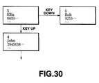
- it may be modified, as shown in Fig.30, to move to a detailed data screen of the preceding name in the list when the rotary key 10j being turned upward and to a detailed data screen of the following name of the list when turned downward. In this case, returning to the menu screen can be executed with the clear key 10h.
- the telephone number list in the embodiment consists of alphabetical letters, it may be written in Japanese Katakanas.
- the shifting from the ordering of names by frequency in the telephone number list to the alphabetical order is made using the rotary key 10j.
- This shifting action may be carried out with a specific shift key or a combination with any of the existing front side keys, e.g. the # key 10c.
- characters on the display 25 of the embodiment are expressed by the two, large and small, fonts, they may comprise three, large, small, and medium, fonts.
- the cursor K is jumped from the top of the current screen to the top of the preceding screen by the scrolling control and from the bottom of the current screen to the bottom of the following screen.
- the scrolling control may be enabled for shifting the cursor K either from the top of the current screen to the top of the preceding screen or from the bottom of the current screen to the bottom of the following screen.
- the muting of the voice signals on the transmitter and speaker is selectively implemented by the movement of the transmitter and will be improved in the controllability. Also, the muting state is recognized by viewing the transmitter at its on-hook position and its fault involvement will be avoided.
- the hold signal As the hold signal is generated and transmitted upon the muting action, it informs a person at the other end of the line that the line remains connected, thus preventing communication error.
Landscapes
- Engineering & Computer Science (AREA)
- Signal Processing (AREA)
- Library & Information Science (AREA)
- Human Computer Interaction (AREA)
- Computer Networks & Wireless Communication (AREA)
- Telephone Set Structure (AREA)
- Mobile Radio Communication Systems (AREA)
Applications Claiming Priority (3)
| Application Number | Priority Date | Filing Date | Title |
|---|---|---|---|
| JP23240894 | 1994-08-31 | ||
| JP232408/94 | 1994-08-31 | ||
| PCT/JP1995/001742 WO1996007262A1 (fr) | 1994-08-31 | 1995-08-31 | Terminal de transmission |
Publications (2)
| Publication Number | Publication Date |
|---|---|
| EP0726668A1 true EP0726668A1 (fr) | 1996-08-14 |
| EP0726668A4 EP0726668A4 (fr) | 1998-12-23 |
Family
ID=16938785
Family Applications (1)
| Application Number | Title | Priority Date | Filing Date |
|---|---|---|---|
| EP95930026A Withdrawn EP0726668A4 (fr) | 1994-08-31 | 1995-08-31 | Terminal de transmission |
Country Status (4)
| Country | Link |
|---|---|
| US (1) | US5930352A (fr) |
| EP (1) | EP0726668A4 (fr) |
| CN (1) | CN1106104C (fr) |
| WO (1) | WO1996007262A1 (fr) |
Cited By (10)
| Publication number | Priority date | Publication date | Assignee | Title |
|---|---|---|---|---|
| GB2308938A (en) * | 1996-01-03 | 1997-07-09 | Motorola Inc | Method and apparatus for operating a communication device |
| WO1998048552A1 (fr) * | 1997-04-23 | 1998-10-29 | Northern Telecom Limited | Defilement avec compression et expansion automatiques |
| WO1998049816A1 (fr) * | 1997-04-28 | 1998-11-05 | Sony Electronics, Inc. | Appareil terminal de communication et procede de selection d'options au moyen d'un bouton-navette |
| WO1999031856A1 (fr) * | 1997-12-18 | 1999-06-24 | Northern Telecom Limited | Interface utilisateur multimode a entrees et sorties vocales et affichage graphique |
| EP0998103A1 (fr) * | 1998-10-30 | 2000-05-03 | Koninklijke Philips Electronics N.V. | Appareil électronique comportant un écran et procédé pour afficher des rubriques d'un menu |
| US6381475B1 (en) | 1998-04-16 | 2002-04-30 | Nokia Mobile Phones Limited | Method and apparatus for menu controlling |
| EP1217810A1 (fr) * | 2000-10-31 | 2002-06-26 | Koninklijke Philips Electronics N.V. | Appareil comprenant un écran de visualisation sur un côté du boítier et une commande d'affichage sur le côté opposé |
| WO2003001779A1 (fr) * | 2001-06-21 | 2003-01-03 | Mauch, Frank | Dispositif de communication |
| US6636125B2 (en) | 2000-11-21 | 2003-10-21 | Koninklijke Philips Electronics N.V. | Modulation device of the pulse width of very high-frequency signals |
| WO2005039156A1 (fr) | 2003-10-17 | 2005-04-28 | Matsushita Electric Industrial Co., Ltd. | Terminal mobile |
Families Citing this family (20)
| Publication number | Priority date | Publication date | Assignee | Title |
|---|---|---|---|---|
| US7088990B1 (en) * | 1996-02-26 | 2006-08-08 | Nokia Mobile Phones, Ltd. | Communication network terminal supporting a plurality of applications |
| US6026161A (en) * | 1996-11-22 | 2000-02-15 | Nokia Mobile Phones Limited | Call rejection |
| FI105308B (fi) * | 1996-12-30 | 2000-07-14 | Nokia Mobile Phones Ltd | Puhelimen soittoäänen ohjelmointi |
| US8466795B2 (en) | 1997-01-21 | 2013-06-18 | Pragmatus Mobile LLC | Personal security and tracking system |
| US7092511B1 (en) * | 1997-12-01 | 2006-08-15 | Sanyo Electric Co., Ltd. | Telephone for retrieving memory content through simple operation |
| JPH11184601A (ja) * | 1997-12-22 | 1999-07-09 | Sony Corp | 携帯情報端末装置、画面スクロール方法、記録媒体およびマイクロコンピュータ装置 |
| JP3068570B2 (ja) * | 1998-10-09 | 2000-07-24 | 埼玉日本電気株式会社 | 携帯型通信装置 |
| USD424555S (en) * | 1999-03-17 | 2000-05-09 | Sony Corporation | Cellular telephone with pivotable belt clip/antenna |
| US8170538B2 (en) | 1999-12-06 | 2012-05-01 | Solocron Media, Llc | Methods and apparatuses for programming user-defined information into electronic devices |
| US6496692B1 (en) | 1999-12-06 | 2002-12-17 | Michael E. Shanahan | Methods and apparatuses for programming user-defined information into electronic devices |
| JP4642292B2 (ja) * | 2001-09-06 | 2011-03-02 | パナソニック株式会社 | 折りたたみ式の無線端末、通話開始方法および通話開始プログラム |
| JP2006222758A (ja) * | 2005-02-10 | 2006-08-24 | Orion Denki Kk | 音声ミュート制御回路を備えた電子装置 |
| KR100768042B1 (ko) * | 2006-11-23 | 2007-10-17 | 삼성전자주식회사 | 돌출형 마이크 모듈을 갖는 휴대용 단말기 |
| US8171177B2 (en) | 2007-06-28 | 2012-05-01 | Apple Inc. | Enhancements to data-driven media management within an electronic device |
| US8676167B2 (en) * | 2008-12-19 | 2014-03-18 | Cellco Partnership | Mobile station with voice call acknowledgement and missed call scheduling |
| US8620653B2 (en) * | 2009-06-18 | 2013-12-31 | Microsoft Corporation | Mute control in audio endpoints |
| US8934645B2 (en) | 2010-01-26 | 2015-01-13 | Apple Inc. | Interaction of sound, silent and mute modes in an electronic device |
| US9065901B2 (en) * | 2012-07-03 | 2015-06-23 | Harris Corporation | Electronic communication devices with integrated microphones |
| FR3033111A1 (fr) * | 2015-02-23 | 2016-08-26 | Orange | Procede d'utilisation d'une gestion automatique de communication, procede et dispositif de gestion automatique de communication et terminal l'utilisant |
| CN106401630A (zh) * | 2016-08-30 | 2017-02-15 | 孙姗姗 | 一种防止支架底座侧滑的装置及使用方法 |
Family Cites Families (11)
| Publication number | Priority date | Publication date | Assignee | Title |
|---|---|---|---|---|
| US4427847A (en) * | 1981-08-10 | 1984-01-24 | Zenith Radio Corporation | Television/telephone system with annunciator and intercom feature |
| JPS58111544U (ja) * | 1982-01-21 | 1983-07-29 | 三洋電機株式会社 | コ−ドレス電話の子機装置 |
| JPS6338438U (fr) * | 1986-08-28 | 1988-03-12 | ||
| US5007081A (en) * | 1989-01-05 | 1991-04-09 | Origin Technology, Inc. | Speech activated telephone |
| US5148471A (en) * | 1989-11-20 | 1992-09-15 | Motorola, Inc. | Communications device with voice recognition and movable element control interface |
| US5175759A (en) * | 1989-11-20 | 1992-12-29 | Metroka Michael P | Communications device with movable element control interface |
| JP3000604B2 (ja) * | 1990-01-18 | 2000-01-17 | ブラザー工業株式会社 | 無線電話装置における自動保留解除方式 |
| DE9005989U1 (de) * | 1990-05-26 | 1990-08-02 | Votronic Entwicklungs- Und Produktionsgesellschaft Fuer Elektronische Geraete Mbh, 6670 St Ingbert | Hör- und Sprecheinheit für in Kraftfahrzeugen angeordnete, mobile Telefone |
| JPH0574051U (ja) * | 1992-03-09 | 1993-10-08 | 船井電機株式会社 | フラップを有する電話機ハンドセット |
| CA2111405A1 (fr) * | 1992-12-18 | 1994-06-19 | Minoru Imura | Radiotelephone |
| JP3303394B2 (ja) * | 1993-02-12 | 2002-07-22 | ソニー株式会社 | 携帯電話機 |
-
1995
- 1995-08-31 CN CN95191036A patent/CN1106104C/zh not_active Expired - Fee Related
- 1995-08-31 US US08/632,441 patent/US5930352A/en not_active Expired - Lifetime
- 1995-08-31 WO PCT/JP1995/001742 patent/WO1996007262A1/fr not_active Ceased
- 1995-08-31 EP EP95930026A patent/EP0726668A4/fr not_active Withdrawn
Cited By (16)
| Publication number | Priority date | Publication date | Assignee | Title |
|---|---|---|---|---|
| US5966671A (en) * | 1996-01-03 | 1999-10-12 | Motorola, Inc. | Radiotelephone having an auxiliary actuator and method for operating said radiotelephone |
| GB2308938A (en) * | 1996-01-03 | 1997-07-09 | Motorola Inc | Method and apparatus for operating a communication device |
| GB2308938B (en) * | 1996-01-03 | 2000-02-09 | Motorola Inc | Method and apparatus for operating a communication device |
| WO1998048552A1 (fr) * | 1997-04-23 | 1998-10-29 | Northern Telecom Limited | Defilement avec compression et expansion automatiques |
| US5923327A (en) * | 1997-04-23 | 1999-07-13 | Bell-Northern Research Ltd. | Scrolling with automatic compression and expansion |
| US6178338B1 (en) | 1997-04-28 | 2001-01-23 | Sony Corporation | Communication terminal apparatus and method for selecting options using a dial shuttle |
| WO1998049816A1 (fr) * | 1997-04-28 | 1998-11-05 | Sony Electronics, Inc. | Appareil terminal de communication et procede de selection d'options au moyen d'un bouton-navette |
| WO1999031856A1 (fr) * | 1997-12-18 | 1999-06-24 | Northern Telecom Limited | Interface utilisateur multimode a entrees et sorties vocales et affichage graphique |
| US6381475B1 (en) | 1998-04-16 | 2002-04-30 | Nokia Mobile Phones Limited | Method and apparatus for menu controlling |
| EP0998103A1 (fr) * | 1998-10-30 | 2000-05-03 | Koninklijke Philips Electronics N.V. | Appareil électronique comportant un écran et procédé pour afficher des rubriques d'un menu |
| EP1217810A1 (fr) * | 2000-10-31 | 2002-06-26 | Koninklijke Philips Electronics N.V. | Appareil comprenant un écran de visualisation sur un côté du boítier et une commande d'affichage sur le côté opposé |
| US6636125B2 (en) | 2000-11-21 | 2003-10-21 | Koninklijke Philips Electronics N.V. | Modulation device of the pulse width of very high-frequency signals |
| WO2003001779A1 (fr) * | 2001-06-21 | 2003-01-03 | Mauch, Frank | Dispositif de communication |
| WO2005039156A1 (fr) | 2003-10-17 | 2005-04-28 | Matsushita Electric Industrial Co., Ltd. | Terminal mobile |
| EP1675357A4 (fr) * | 2003-10-17 | 2010-05-05 | Panasonic Corp | Terminal mobile |
| US7801579B2 (en) | 2003-10-17 | 2010-09-21 | Panasonic Corporation | Mobile terminal apparatus eliminating noise in transition state |
Also Published As
| Publication number | Publication date |
|---|---|
| CN1106104C (zh) | 2003-04-16 |
| EP0726668A4 (fr) | 1998-12-23 |
| WO1996007262A1 (fr) | 1996-03-07 |
| US5930352A (en) | 1999-07-27 |
| CN1136874A (zh) | 1996-11-27 |
Similar Documents
| Publication | Publication Date | Title |
|---|---|---|
| US5930352A (en) | Communication terminal apparatus | |
| US5715311A (en) | Communication terminal apparatus | |
| US6223058B1 (en) | Communication terminal apparatus and control method thereof | |
| JPWO1996007244A1 (ja) | 通信端末装置 | |
| EP0469077B1 (fr) | Dispositif d'enregistrement de la voix fonctionnant avec des stations d'émission/récéption | |
| US6456841B1 (en) | Mobile communication apparatus notifying user of reproduction waiting information effectively | |
| JPH09261759A (ja) | 通信端末装置 | |
| EP0961460A2 (fr) | Dispositif pour générer automatiquement un numéro d'abonné auquel un message court doit être envoyé | |
| JP3067006B2 (ja) | 通信端末装置 | |
| JP4569939B2 (ja) | 携帯形電話機 | |
| KR100568561B1 (ko) | 휴대무선기 | |
| JP3045368B2 (ja) | 通信端末装置 | |
| JP3013973B2 (ja) | 通信端末装置 | |
| JPH10271192A (ja) | 携帯電話端末 | |
| USRE39959E1 (en) | Communication terminal apparatus and control method thereof | |
| JP2001157264A (ja) | 無線通信端末及びそれに用いる自動機能設定方法 | |
| JPH0879364A (ja) | 通信端末装置 | |
| US20030083022A1 (en) | Mobile radio terminal | |
| JP3013987B2 (ja) | 通信端末装置 | |
| JP3067007B2 (ja) | 通信端末装置 | |
| JP3067018B2 (ja) | 通信端末装置 | |
| RU2180989C2 (ru) | Способ обеспечения набираемого извещающего сообщения в телефонном терминальном аппарате | |
| JPH1093678A (ja) | 通信端末装置 | |
| JPWO1996007262A1 (ja) | 通信端末装置 | |
| JPH1098519A (ja) | 通信端末装置 |
Legal Events
| Date | Code | Title | Description |
|---|---|---|---|
| PUAI | Public reference made under article 153(3) epc to a published international application that has entered the european phase |
Free format text: ORIGINAL CODE: 0009012 |
|
| 17P | Request for examination filed |
Effective date: 19960425 |
|
| AK | Designated contracting states |
Kind code of ref document: A1 Designated state(s): DE FR GB |
|
| A4 | Supplementary search report drawn up and despatched | ||
| AK | Designated contracting states |
Kind code of ref document: A4 Designated state(s): DE FR GB |
|
| STAA | Information on the status of an ep patent application or granted ep patent |
Free format text: STATUS: THE APPLICATION HAS BEEN WITHDRAWN |
|
| 18W | Application withdrawn |
Withdrawal date: 20020628 |