EP0727144A1 - Gerät zum geordneten Aufhängen von Gegenständen, insbesondere von Wurstwaren, auf umsetzbare Träger - Google Patents
Gerät zum geordneten Aufhängen von Gegenständen, insbesondere von Wurstwaren, auf umsetzbare Träger Download PDFInfo
- Publication number
- EP0727144A1 EP0727144A1 EP96830051A EP96830051A EP0727144A1 EP 0727144 A1 EP0727144 A1 EP 0727144A1 EP 96830051 A EP96830051 A EP 96830051A EP 96830051 A EP96830051 A EP 96830051A EP 0727144 A1 EP0727144 A1 EP 0727144A1
- Authority
- EP
- European Patent Office
- Prior art keywords
- chain
- hooks
- plier
- pair
- supports
- Prior art date
- Legal status (The legal status is an assumption and is not a legal conclusion. Google has not performed a legal analysis and makes no representation as to the accuracy of the status listed.)
- Granted
Links
Images


Classifications
-
- A—HUMAN NECESSITIES
- A22—BUTCHERING; MEAT TREATMENT; PROCESSING POULTRY OR FISH
- A22C—PROCESSING MEAT, POULTRY, OR FISH
- A22C15/00—Apparatus for hanging-up meat or sausages
- A22C15/001—Specially adapted for hanging or conveying several sausages or strips of meat
-
- B—PERFORMING OPERATIONS; TRANSPORTING
- B65—CONVEYING; PACKING; STORING; HANDLING THIN OR FILAMENTARY MATERIAL
- B65G—TRANSPORT OR STORAGE DEVICES, e.g. CONVEYORS FOR LOADING OR TIPPING, SHOP CONVEYOR SYSTEMS OR PNEUMATIC TUBE CONVEYORS
- B65G47/00—Article or material-handling devices associated with conveyors; Methods employing such devices
- B65G47/52—Devices for transferring articles or materials between conveyors i.e. discharging or feeding devices
- B65G47/60—Devices for transferring articles or materials between conveyors i.e. discharging or feeding devices to or from conveyors of the suspended, e.g. trolley, type
- B65G47/61—Devices for transferring articles or materials between conveyors i.e. discharging or feeding devices to or from conveyors of the suspended, e.g. trolley, type for articles
Definitions
- the invention relates to an apparatus for hanging objects in an orderly fashion, especially sacked meats, on transferable supports.
- the prior art teaches the method of hanging sacked meats on rods which are then moved and located on special trucks or in chambers so that operations such as seasoning (or other operations which are part of the working progress of the meats) can take place.
- the hanging operation using the loop provided on the sacks, on to the support and spacing the sacks on the rod according to their size and dimensions, is at present performed manually. This leads to the drawback of requiring a considerable amount of work time and labour effort.
- the present invention proposes to obviate the limitations and drawbacks of the prior art by providing an apparatus for orderedly hanging objects, especially sacked meats, on transferable supports, which apparatus is easily and simply insertable into the normal working cycle of the meats.
- An advantage of the invention is that it works very quickly and most precisely.
- 1 denotes in its entirety a transport line along which fork-hooks are caused to advance.
- the hooks 2 are constrained to a chain 3 and are arranged consecutively one after another at a predetermined reciprocal distance.
- the chain 3 is constituted by a cardan chain, provided with pairs of guide wheels 33 each arranged with an axis orthogonal to another and to the advancement direction of the chain.
- the guide wheels 33 are uniformly distanced in a longitudinal direction of the chain 3, as are the hooks 2.
- the hooks 2 are pivoted in the chain 3 links by means of pivots 10 having axes perpendicular to the chain advancement direction along the line 1.
- the line 1 is represented by a straight horizontal line in the figures, where the chain 3 is guided by a plurality of straight horizontal guides 15.
- the straight horizontal guides 15 By means of the straight horizontal guides 15 the chain 3 is kept constantly oriented so that the pivots 10 are always arranged with their axes parallel, horizontal and perpendicular to the direction of advancement of the chain 3.
- the hooks 2 are symmetrically structured and exhibit two teeth 4 positioned at a predetermined distance one from the other, which teeth 4 are destined to receive the loop 19 of an object to be hung, precisely in the present case a sacked meat product 20.
- the hooks 2 are further provided, in an opposite position with respect to the pivots 10, with pins 13 having a function of interacting with a device 5 for producing, on command, a partial tilting of the hooks 2 about the pivots 10.
- the device 5 comprises a shuttle 11 constrained to a device 5 of known type which causes the shuttle 11 to position itself along a straight guide 6 disposed parallel to the straight horizontal guides 15.
- the shuttle 11 is provided with a shaped appendage 12 predisposed to interact with the pins 13 of the hooks.
- the shaped appendage 12, acting together with the pins 13 of a hook 2 produces a partial rotation of the hook 2 about the pivot 10, bringing the hook 2 into a position at which the teeth 4 are inclinedly disposed in a downwards direction. Obviously in this position the teeth 4 would not be able to receive and hold a loop 19 previously attached thereon. In the normal position, the teeth 4 are arranged horizontally or slightly upwards-turned so that they can in fact hold on to a loop 19.
- the possibility of locating the device 5 at any point along the guide 6 enables (at a predetermined point) a hook 2 carrying an object by its loop 19 to be unloaded.
- the hooks 2 are forked so that the loop 19 hooked thereon are kept open in order that same can be transferred on to a support 7, precisely a rod of the type utilized for orderedly hanging sacked meat products 20.
- a support 7 is predisposed and supported at both ends below the straight tract of the transport line 1 so that the loop 19 of the hung sacked meat hanging from a hook 2 and transiting along said line 1 is brought into a position where it is met by the support 7.
- the two teeth 4 of each hook 2 are positioned at a reciprocal distance which is greater than the maximum dimension (ie. the diameter) of the support 7.
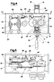
- the supports 7 are automatically loaded, positioned below the line 1 and removed therefrom, once loaded with the sacked meat product 20, by a group comprising a feeder 26 of the unloaded supports 7, a first pair of chain conveyors 27, rotatable about a fixed axis parallel to the advancement direction of the hooks 2, and a second pair of chain conveyors 30 activated synchronically and predisposed with respect to the first pair of chain conveyors 27 in such a way as to constitute a continuation thereof.
- the feeder 26 is schematically composed of an inclined plane along which the supports 7 are predisposed side-by-side and from which they are released one at a time then to be deposited on the first pair of chain conveyors 27.
- the two chain conveyors 27 are synchronically activated and each exhibit a ring-wound chain associated to disks 28 consecutively arranged such that between one disk 28 and a next a sort of cavity wherein the support 7 (which is cylindrical) can rest.
- each support 7 is provided at either end with two specially distanced channels 17.
- the two externalmost channels 17 are located at a reciprocal distance which permits them to insert contactingly into the disks 28 of the two chain conveyors 27.
- Each of the two chain conveyors 27 exhibits a frame 29 which can be commanded to rotate in two directions about a fixed axis perpendicular to the transport direction between a horizontal work position and an inactive position at which the transporter is predisposed with the unloading end downwards so as not to interfere with the sacked meat products 20 hung and moving in a parallel direction to that of the transport line 1.
- the passage from one position to another of the single chain conveyors 27 is realized by means of a cylinder 31.
- the movement of the upper branches of the chain conveyors 27 in the direction indicated by the arrow 32 produces a displacement of the single supports 7, supplied by the feeder 26 below the transport line 1 along which the hooks 2 transit.
- a second pair of chain conveyors 30 receive the loaded supports 7 from the chain conveyors 27 and transfer same to a subsequent phase of the work cycle.
- the chain conveyors 30 are also associated with relative disks 28 predisposed consecutively in such a way that the ends of the single supports 7, unloaded from the first chain conveyors 27, can rest in the cavity identified by two consecutive disks 28.
- the supports 7 are provided with a second pair of channels 17 arranged at a reciprocal distance, which is equal to the distance between the disks 28 associated to the chains of the second pair of chain conveyors 30.
- the presence of the channels 17 has the aim of preventing the supports 7 from moving in a perpendicular direction to the advancement direction.
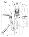
- a gripping organ 16 having the task of positioning and securing an end of the support 7, and at another side thereof are positioned two pliers 8 and 9 which alternatingly grip the other end of the support 7 by means of a mechanism operating in synchrony with the advancement of the single hooks 2 along the line 1.
- the two pliers 8 and 9 are located at a reciprocal distance not less than the size of the mass, in the advancement direction, of a single hook 2, and are both constituted by symmetrically-opening arms 14 provided with shaped impressions for embracing the end of the supports 7.
- the mechanism operating in synchrony with the advancement of the single hooks 2 along the line 1 comprises a rotating organ 46 for the movement of the chain 3 which, in the illustrated embodiment, is constituted by a screw having a helicoid channel, in other words a thread, in which the upper wheels 33 of the chain 3 engage.
- a rotating organ 46 for the movement of the chain 3 which, in the illustrated embodiment, is constituted by a screw having a helicoid channel, in other words a thread, in which the upper wheels 33 of the chain 3 engage.
- a mechanical transmission 18 transmits (with a predetermined gear ratio) the rotation of the rotating organ 46 to a cam 21 commanding the alternated activation of the pliers 8 and 9 synchronically with the transit of the hooks 2 between the organs.
- the cam 21 is provided with a channel 34 in which the pivots 36 and 37 of two rocker arms 22 engage, said rocker arms 22 having their other two ends hinged to two con rods 23.
- Each of the con rods 23 is constrained at another end thereof to an appendage 40 in turn solidly constrained to one of the two arms 14 provided on each plier 8 and 9.
- the two arms 14 of each plier are journalled about two fixed axes parallel to the advancement direction of the chain 3 and are reciprocally constrained to rotate equally and in opposite directions by two identical gear wheels 24 reciprocally enmeshed and fixed one to an arm 14 and the other to the other arm 14 of the arm pair.
- the above-described mechanism permits production, through the rotation of the cam 21, the alternated opening of the pliers 8 and 9 in such a way that when one of the two said pliers 8 and 9 is open, the other is closed. This results in a condition where the support 7 is always supported at the second end thereof.
- the synchronization is regulated so that when a hook 2 nears the plier 8 said plier 8 opens with a movement of the arms 14 from a closed position A to an open position B, while plier 9 remains closed (with arms 14 in position A).
- the cam 21 is designed so that as soon as the hook 2 is moved internalwise between the two pliers 8 and 9, plier 8 closes bringing the arms 14 into position A and plier 9 opens, bringing the arms 14 into position B. In this way, the support 7 does not remain without a rest when the hook 2 is receiving. Once the hook 2 has passed on from the plier 9, said plier 9 is closed bringing its arms 14 from position B into position A.
- the hook 2 is thus free to transit alon the lwhole length of the support 9 up until when it meets the tilting device 5, which unloads the sacked meat products 20 by unhooking the loop 19 from the support 7.
- the con rods 23 exhibits a command-variable length.
- the con rods 23 are constituted by pneumatic cylinders which are actuated on command in synchrony with the transfer movement of a single support 7 towards and from the loading position below the transport line 1.
Landscapes
- Engineering & Computer Science (AREA)
- Life Sciences & Earth Sciences (AREA)
- Mechanical Engineering (AREA)
- Wood Science & Technology (AREA)
- Zoology (AREA)
- Food Science & Technology (AREA)
- Chain Conveyers (AREA)
- Food-Manufacturing Devices (AREA)
- Processing Of Meat And Fish (AREA)
- Specific Conveyance Elements (AREA)
- Load-Engaging Elements For Cranes (AREA)
Applications Claiming Priority (2)
| Application Number | Priority Date | Filing Date | Title |
|---|---|---|---|
| IT95MO000022A IT1279360B1 (it) | 1995-02-17 | 1995-02-17 | Apparecchiatura per appendere ordinatamente oggetti, in particolare insaccati, su supporti trasferibili |
| ITMO950022 | 1995-02-17 |
Publications (2)
| Publication Number | Publication Date |
|---|---|
| EP0727144A1 true EP0727144A1 (de) | 1996-08-21 |
| EP0727144B1 EP0727144B1 (de) | 1998-05-13 |
Family
ID=11385795
Family Applications (1)
| Application Number | Title | Priority Date | Filing Date |
|---|---|---|---|
| EP96830051A Expired - Lifetime EP0727144B1 (de) | 1995-02-17 | 1996-02-06 | Gerät zum geordneten Aufhängen von Gegenständen, insbesondere von Wurstwaren, auf umsetzbare Träger |
Country Status (6)
| Country | Link |
|---|---|
| US (1) | US5782336A (de) |
| EP (1) | EP0727144B1 (de) |
| AT (1) | ATE165951T1 (de) |
| DE (1) | DE69600277T2 (de) |
| ES (1) | ES2118667T3 (de) |
| IT (1) | IT1279360B1 (de) |
Cited By (4)
| Publication number | Priority date | Publication date | Assignee | Title |
|---|---|---|---|---|
| EP1464225A3 (de) * | 1998-02-23 | 2005-08-17 | Ve.Ma.C. S.R.L. | Mittel zum Aufhängen von Objekten |
| EP1897446A3 (de) * | 2006-09-06 | 2008-06-11 | Poly-clip System GmbH & Co. KG | Fertigungslinie zur Herstellung wurstförmiger Produkte |
| US7942728B2 (en) * | 2003-07-16 | 2011-05-17 | Poly-Clip Systems Gmbh & Co. Kg | Transport apparatus for transporting articles hanging on loops |
| EP2384638B1 (de) | 2010-05-04 | 2020-08-26 | Poly-clip System GmbH & Co. KG | Robotervorrichtung und Verfahren zum Einfügen oder Entfernen von stabförmigen Elementen |
Families Citing this family (1)
| Publication number | Priority date | Publication date | Assignee | Title |
|---|---|---|---|---|
| US9527097B2 (en) * | 2013-11-05 | 2016-12-27 | Torrent Systems Llc | Spray coating system and method |
Citations (5)
| Publication number | Priority date | Publication date | Assignee | Title |
|---|---|---|---|---|
| DE3437830A1 (de) * | 1984-10-16 | 1986-04-24 | Günther 8046 Garching Leidig | Verfahren und vorrichtung zum selbsttaetigen aufreihen von mit halteschlaufen versehenen gegenstaenden auf haltestangen |
| FR2619285A1 (fr) * | 1987-08-10 | 1989-02-17 | Freres & Cie Charles | Installation et procede permettant de saisir des produits de charcuterie par leur ligaturage apres nouage, et de les positionner sur des barres de presentation et de sechage |
| EP0417451A1 (de) * | 1989-09-15 | 1991-03-20 | Günter Kollross | Verfahren und Vorrichtung zum Zu- und Abführen von Rauch- oder Kochstäben zum automatischen Aufhängen von Schlaufen versehenen Würsten |
| EP0424675A1 (de) * | 1989-10-27 | 1991-05-02 | Günter Kollross | Verfahren und Vorrichtung zum mechanisierten Aufhängen von Würsten |
| WO1992003929A1 (en) * | 1990-08-31 | 1992-03-19 | Herman Daniel Kloppenburg | Method and arrangement for preparing a packaged substance for smoking and/or other treatment |
Family Cites Families (5)
| Publication number | Priority date | Publication date | Assignee | Title |
|---|---|---|---|---|
| US570025A (en) * | 1896-10-27 | Butcheeina | ||
| US2752883A (en) * | 1952-06-04 | 1956-07-03 | Ransburg Electro Coating Corp | Apparatus for conveying articles |
| US3533495A (en) * | 1968-08-14 | 1970-10-13 | Schmidt Wallace Inc | Apparatus for handling wieners and the like |
| US4953495A (en) * | 1989-02-01 | 1990-09-04 | Blodgett & Blodgett | Article coating system |
| US5261520A (en) * | 1992-11-04 | 1993-11-16 | Am International, Inc. | Custodial book transfer system |
-
1995
- 1995-02-17 IT IT95MO000022A patent/IT1279360B1/it active IP Right Grant
-
1996
- 1996-02-02 US US08/596,443 patent/US5782336A/en not_active Expired - Lifetime
- 1996-02-06 AT AT96830051T patent/ATE165951T1/de not_active IP Right Cessation
- 1996-02-06 DE DE69600277T patent/DE69600277T2/de not_active Expired - Lifetime
- 1996-02-06 ES ES96830051T patent/ES2118667T3/es not_active Expired - Lifetime
- 1996-02-06 EP EP96830051A patent/EP0727144B1/de not_active Expired - Lifetime
Patent Citations (5)
| Publication number | Priority date | Publication date | Assignee | Title |
|---|---|---|---|---|
| DE3437830A1 (de) * | 1984-10-16 | 1986-04-24 | Günther 8046 Garching Leidig | Verfahren und vorrichtung zum selbsttaetigen aufreihen von mit halteschlaufen versehenen gegenstaenden auf haltestangen |
| FR2619285A1 (fr) * | 1987-08-10 | 1989-02-17 | Freres & Cie Charles | Installation et procede permettant de saisir des produits de charcuterie par leur ligaturage apres nouage, et de les positionner sur des barres de presentation et de sechage |
| EP0417451A1 (de) * | 1989-09-15 | 1991-03-20 | Günter Kollross | Verfahren und Vorrichtung zum Zu- und Abführen von Rauch- oder Kochstäben zum automatischen Aufhängen von Schlaufen versehenen Würsten |
| EP0424675A1 (de) * | 1989-10-27 | 1991-05-02 | Günter Kollross | Verfahren und Vorrichtung zum mechanisierten Aufhängen von Würsten |
| WO1992003929A1 (en) * | 1990-08-31 | 1992-03-19 | Herman Daniel Kloppenburg | Method and arrangement for preparing a packaged substance for smoking and/or other treatment |
Cited By (8)
| Publication number | Priority date | Publication date | Assignee | Title |
|---|---|---|---|---|
| EP1464225A3 (de) * | 1998-02-23 | 2005-08-17 | Ve.Ma.C. S.R.L. | Mittel zum Aufhängen von Objekten |
| US7942728B2 (en) * | 2003-07-16 | 2011-05-17 | Poly-Clip Systems Gmbh & Co. Kg | Transport apparatus for transporting articles hanging on loops |
| EP1897446A3 (de) * | 2006-09-06 | 2008-06-11 | Poly-clip System GmbH & Co. KG | Fertigungslinie zur Herstellung wurstförmiger Produkte |
| EP2241187A1 (de) * | 2006-09-06 | 2010-10-20 | Poly-clip System GmbH & Co. KG | Beschickungsmaschine für eine Fertigungslinie zur Herstellung wurstförmiger Produkte |
| RU2438333C2 (ru) * | 2006-09-06 | 2012-01-10 | Поли-Клип Зюстем Гмбх Унд Ко.Кг | Способ управления поточной линией, поточная линия для изготовления колбасообразных продуктов, клипсатор для поточной линии и загрузочная машина для поточной линии |
| US8366523B2 (en) | 2006-09-06 | 2013-02-05 | Poly-Clip System Gmbh & Co. Kg | Feeding machine for manufacture of sausage-shaped products |
| US8696415B2 (en) | 2006-09-06 | 2014-04-15 | Poly-Clip System Gmbh & Co. Kg | Clip machine for the manufacture of sausage-shaped products |
| EP2384638B1 (de) | 2010-05-04 | 2020-08-26 | Poly-clip System GmbH & Co. KG | Robotervorrichtung und Verfahren zum Einfügen oder Entfernen von stabförmigen Elementen |
Also Published As
| Publication number | Publication date |
|---|---|
| DE69600277D1 (de) | 1998-06-18 |
| ES2118667T3 (es) | 1998-09-16 |
| ATE165951T1 (de) | 1998-05-15 |
| DE69600277T2 (de) | 1999-01-28 |
| EP0727144B1 (de) | 1998-05-13 |
| IT1279360B1 (it) | 1997-12-09 |
| US5782336A (en) | 1998-07-21 |
| ITMO950022A1 (it) | 1996-08-17 |
Similar Documents
| Publication | Publication Date | Title |
|---|---|---|
| US5100364A (en) | Process and device for the mechanized suspension of sausages | |
| US4644607A (en) | Device for applying a strand of sausage or the like to a smoking rod | |
| US4761854A (en) | Suspension device for strings of sausage links | |
| US5082419A (en) | Process for the input and carrying away of smoking or cooking rods for automatic suspension of a plurality of sausages | |
| US7614942B2 (en) | Smoke stick gripper | |
| US20150101700A1 (en) | Twisting apparatus | |
| SE457792B (sv) | Kabelvaexlingsanordning foer anvaendning vid vaexling fraan en foersta roterbar trumma till en andra roterbar trumma | |
| JP2501399B2 (ja) | 整合させた食品の堆積を容器内に転送する装置 | |
| EP0727144B1 (de) | Gerät zum geordneten Aufhängen von Gegenständen, insbesondere von Wurstwaren, auf umsetzbare Träger | |
| EP0545995B1 (de) | Verfahren und anordnung zum vorbereiten einer verpackten substanz zum räuchern und/oder einer anderen behandlung | |
| US5238353A (en) | Device for the input and carrying away of smoking or cooking rods for automatic suspension of a plurality of sausages | |
| US3345003A (en) | Apparatus for continuously winding threads and like filamentary material on to a succession of bobbins | |
| JPH04289049A (ja) | ケーブル片を搬送するための装置 | |
| US4336875A (en) | Apparatus for the transfer of hanks | |
| US10986846B2 (en) | Indexing device | |
| US4359153A (en) | Three axis transfer apparatus | |
| US3747786A (en) | Apparatus for extracting and feeding tubes to a machine for filling the tubes with a suitable material | |
| EP0941664A2 (de) | Mittel zum Aufhängen von Nahrungsmitteln | |
| US3968548A (en) | Lead transfer mechanism | |
| EP1518461A2 (de) | Vorrichtung und Verfahren zur Übertragung von Gegenständen | |
| JPH02231048A (ja) | 麺の捌き・引延し機 | |
| EP1975094A1 (de) | Fördervorrichtung | |
| SU806426A1 (ru) | Автоматическа поточна лини дл пРОизВОдСТВА КЕРАМичЕСКиХглАзуРОВАННыХ ТРубОК | |
| EP0429126B1 (de) | Vorrichtung zum Bündeln | |
| SU1169587A2 (ru) | Устройство дл сн ти туш м са с подвесного пути |
Legal Events
| Date | Code | Title | Description |
|---|---|---|---|
| PUAI | Public reference made under article 153(3) epc to a published international application that has entered the european phase |
Free format text: ORIGINAL CODE: 0009012 |
|
| AK | Designated contracting states |
Kind code of ref document: A1 Designated state(s): AT BE CH DE DK ES FR GB IT LI NL SE |
|
| 17P | Request for examination filed |
Effective date: 19970205 |
|
| GRAG | Despatch of communication of intention to grant |
Free format text: ORIGINAL CODE: EPIDOS AGRA |
|
| 17Q | First examination report despatched |
Effective date: 19971219 |
|
| GRAG | Despatch of communication of intention to grant |
Free format text: ORIGINAL CODE: EPIDOS AGRA |
|
| GRAH | Despatch of communication of intention to grant a patent |
Free format text: ORIGINAL CODE: EPIDOS IGRA |
|
| GRAH | Despatch of communication of intention to grant a patent |
Free format text: ORIGINAL CODE: EPIDOS IGRA |
|
| GRAA | (expected) grant |
Free format text: ORIGINAL CODE: 0009210 |
|
| AK | Designated contracting states |
Kind code of ref document: B1 Designated state(s): AT BE CH DE DK ES FR GB IT LI NL SE |
|
| PG25 | Lapsed in a contracting state [announced via postgrant information from national office to epo] |
Ref country code: NL Free format text: LAPSE BECAUSE OF FAILURE TO SUBMIT A TRANSLATION OF THE DESCRIPTION OR TO PAY THE FEE WITHIN THE PRESCRIBED TIME-LIMIT Effective date: 19980513 Ref country code: LI Free format text: LAPSE BECAUSE OF FAILURE TO SUBMIT A TRANSLATION OF THE DESCRIPTION OR TO PAY THE FEE WITHIN THE PRESCRIBED TIME-LIMIT Effective date: 19980513 Ref country code: CH Free format text: LAPSE BECAUSE OF FAILURE TO SUBMIT A TRANSLATION OF THE DESCRIPTION OR TO PAY THE FEE WITHIN THE PRESCRIBED TIME-LIMIT Effective date: 19980513 Ref country code: BE Free format text: LAPSE BECAUSE OF FAILURE TO SUBMIT A TRANSLATION OF THE DESCRIPTION OR TO PAY THE FEE WITHIN THE PRESCRIBED TIME-LIMIT Effective date: 19980513 Ref country code: AT Free format text: LAPSE BECAUSE OF FAILURE TO SUBMIT A TRANSLATION OF THE DESCRIPTION OR TO PAY THE FEE WITHIN THE PRESCRIBED TIME-LIMIT Effective date: 19980513 |
|
| REF | Corresponds to: |
Ref document number: 165951 Country of ref document: AT Date of ref document: 19980515 Kind code of ref document: T |
|
| REG | Reference to a national code |
Ref country code: CH Ref legal event code: EP |
|
| REF | Corresponds to: |
Ref document number: 69600277 Country of ref document: DE Date of ref document: 19980618 |
|
| ITF | It: translation for a ep patent filed | ||
| PG25 | Lapsed in a contracting state [announced via postgrant information from national office to epo] |
Ref country code: SE Free format text: LAPSE BECAUSE OF FAILURE TO SUBMIT A TRANSLATION OF THE DESCRIPTION OR TO PAY THE FEE WITHIN THE PRESCRIBED TIME-LIMIT Effective date: 19980813 Ref country code: DK Free format text: LAPSE BECAUSE OF FAILURE TO SUBMIT A TRANSLATION OF THE DESCRIPTION OR TO PAY THE FEE WITHIN THE PRESCRIBED TIME-LIMIT Effective date: 19980813 |
|
| REG | Reference to a national code |
Ref country code: ES Ref legal event code: FG2A Ref document number: 2118667 Country of ref document: ES Kind code of ref document: T3 |
|
| ET | Fr: translation filed | ||
| NLV1 | Nl: lapsed or annulled due to failure to fulfill the requirements of art. 29p and 29m of the patents act | ||
| REG | Reference to a national code |
Ref country code: CH Ref legal event code: PL |
|
| PLBE | No opposition filed within time limit |
Free format text: ORIGINAL CODE: 0009261 |
|
| STAA | Information on the status of an ep patent application or granted ep patent |
Free format text: STATUS: NO OPPOSITION FILED WITHIN TIME LIMIT |
|
| 26N | No opposition filed | ||
| REG | Reference to a national code |
Ref country code: GB Ref legal event code: IF02 |
|
| REG | Reference to a national code |
Ref country code: GB Ref legal event code: 732E |
|
| REG | Reference to a national code |
Ref country code: FR Ref legal event code: TP |
|
| REG | Reference to a national code |
Ref country code: ES Ref legal event code: PC2A |
|
| REG | Reference to a national code |
Ref country code: FR Ref legal event code: PLFP Year of fee payment: 20 |
|
| PGFP | Annual fee paid to national office [announced via postgrant information from national office to epo] |
Ref country code: ES Payment date: 20150326 Year of fee payment: 20 Ref country code: IT Payment date: 20150225 Year of fee payment: 20 |
|
| PGFP | Annual fee paid to national office [announced via postgrant information from national office to epo] |
Ref country code: GB Payment date: 20150227 Year of fee payment: 20 Ref country code: FR Payment date: 20150227 Year of fee payment: 20 |
|
| PGFP | Annual fee paid to national office [announced via postgrant information from national office to epo] |
Ref country code: DE Payment date: 20150429 Year of fee payment: 20 |
|
| REG | Reference to a national code |
Ref country code: DE Ref legal event code: R071 Ref document number: 69600277 Country of ref document: DE |
|
| REG | Reference to a national code |
Ref country code: GB Ref legal event code: PE20 Expiry date: 20160205 |
|
| PG25 | Lapsed in a contracting state [announced via postgrant information from national office to epo] |
Ref country code: GB Free format text: LAPSE BECAUSE OF EXPIRATION OF PROTECTION Effective date: 20160205 |
|
| REG | Reference to a national code |
Ref country code: ES Ref legal event code: FD2A Effective date: 20160526 |
|
| PG25 | Lapsed in a contracting state [announced via postgrant information from national office to epo] |
Ref country code: ES Free format text: LAPSE BECAUSE OF EXPIRATION OF PROTECTION Effective date: 20160207 |