EP0727573B1 - Verfahren zur Beheizung eines Drosselklappenstutzens und Saugrohr für eine Brennkraftmaschine - Google Patents
Verfahren zur Beheizung eines Drosselklappenstutzens und Saugrohr für eine Brennkraftmaschine Download PDFInfo
- Publication number
- EP0727573B1 EP0727573B1 EP96101499A EP96101499A EP0727573B1 EP 0727573 B1 EP0727573 B1 EP 0727573B1 EP 96101499 A EP96101499 A EP 96101499A EP 96101499 A EP96101499 A EP 96101499A EP 0727573 B1 EP0727573 B1 EP 0727573B1
- Authority
- EP
- European Patent Office
- Prior art keywords
- electric motor
- throttle valve
- internal combustion
- combustion engine
- heating
- Prior art date
- Legal status (The legal status is an assumption and is not a legal conclusion. Google has not performed a legal analysis and makes no representation as to the accuracy of the status listed.)
- Expired - Lifetime
Links
Images
Classifications
-
- F—MECHANICAL ENGINEERING; LIGHTING; HEATING; WEAPONS; BLASTING
- F02—COMBUSTION ENGINES; HOT-GAS OR COMBUSTION-PRODUCT ENGINE PLANTS
- F02D—CONTROLLING COMBUSTION ENGINES
- F02D9/00—Controlling engines by throttling air or fuel-and-air induction conduits or exhaust conduits
- F02D9/08—Throttle valves specially adapted therefor; Arrangements of such valves in conduits
- F02D9/10—Throttle valves specially adapted therefor; Arrangements of such valves in conduits having pivotally-mounted flaps
- F02D9/1035—Details of the valve housing
-
- F—MECHANICAL ENGINEERING; LIGHTING; HEATING; WEAPONS; BLASTING
- F02—COMBUSTION ENGINES; HOT-GAS OR COMBUSTION-PRODUCT ENGINE PLANTS
- F02D—CONTROLLING COMBUSTION ENGINES
- F02D11/00—Arrangements for, or adaptations to, non-automatic engine control initiation means, e.g. operator initiated
- F02D11/06—Arrangements for, or adaptations to, non-automatic engine control initiation means, e.g. operator initiated characterised by non-mechanical control linkages, e.g. fluid control linkages or by control linkages with power drive or assistance
- F02D11/10—Arrangements for, or adaptations to, non-automatic engine control initiation means, e.g. operator initiated characterised by non-mechanical control linkages, e.g. fluid control linkages or by control linkages with power drive or assistance of the electric type
-
- F—MECHANICAL ENGINEERING; LIGHTING; HEATING; WEAPONS; BLASTING
- F02—COMBUSTION ENGINES; HOT-GAS OR COMBUSTION-PRODUCT ENGINE PLANTS
- F02M—SUPPLYING COMBUSTION ENGINES IN GENERAL WITH COMBUSTIBLE MIXTURES OR CONSTITUENTS THEREOF
- F02M35/00—Combustion-air cleaners, air intakes, intake silencers, or induction systems specially adapted for, or arranged on, internal-combustion engines
- F02M35/10—Air intakes; Induction systems
- F02M35/10242—Devices or means connected to or integrated into air intakes; Air intakes combined with other engine or vehicle parts
- F02M35/10268—Heating, cooling or thermal insulating means
-
- F—MECHANICAL ENGINEERING; LIGHTING; HEATING; WEAPONS; BLASTING
- F02—COMBUSTION ENGINES; HOT-GAS OR COMBUSTION-PRODUCT ENGINE PLANTS
- F02M—SUPPLYING COMBUSTION ENGINES IN GENERAL WITH COMBUSTIBLE MIXTURES OR CONSTITUENTS THEREOF
- F02M35/00—Combustion-air cleaners, air intakes, intake silencers, or induction systems specially adapted for, or arranged on, internal-combustion engines
- F02M35/10—Air intakes; Induction systems
- F02M35/10373—Sensors for intake systems
- F02M35/1038—Sensors for intake systems for temperature or pressure
-
- F—MECHANICAL ENGINEERING; LIGHTING; HEATING; WEAPONS; BLASTING
- F02—COMBUSTION ENGINES; HOT-GAS OR COMBUSTION-PRODUCT ENGINE PLANTS
- F02D—CONTROLLING COMBUSTION ENGINES
- F02D11/00—Arrangements for, or adaptations to, non-automatic engine control initiation means, e.g. operator initiated
- F02D11/06—Arrangements for, or adaptations to, non-automatic engine control initiation means, e.g. operator initiated characterised by non-mechanical control linkages, e.g. fluid control linkages or by control linkages with power drive or assistance
- F02D11/10—Arrangements for, or adaptations to, non-automatic engine control initiation means, e.g. operator initiated characterised by non-mechanical control linkages, e.g. fluid control linkages or by control linkages with power drive or assistance of the electric type
- F02D2011/101—Arrangements for, or adaptations to, non-automatic engine control initiation means, e.g. operator initiated characterised by non-mechanical control linkages, e.g. fluid control linkages or by control linkages with power drive or assistance of the electric type characterised by the means for actuating the throttles
- F02D2011/102—Arrangements for, or adaptations to, non-automatic engine control initiation means, e.g. operator initiated characterised by non-mechanical control linkages, e.g. fluid control linkages or by control linkages with power drive or assistance of the electric type characterised by the means for actuating the throttles at least one throttle being moved only by an electric actuator
-
- F—MECHANICAL ENGINEERING; LIGHTING; HEATING; WEAPONS; BLASTING
- F05—INDEXING SCHEMES RELATING TO ENGINES OR PUMPS IN VARIOUS SUBCLASSES OF CLASSES F01-F04
- F05C—INDEXING SCHEME RELATING TO MATERIALS, MATERIAL PROPERTIES OR MATERIAL CHARACTERISTICS FOR MACHINES, ENGINES OR PUMPS OTHER THAN NON-POSITIVE-DISPLACEMENT MACHINES OR ENGINES
- F05C2201/00—Metals
- F05C2201/02—Light metals
- F05C2201/021—Aluminium
Definitions
- the invention relates to a method for heating a throttle valve assembly in an internal combustion engine according to the preamble of claim 1 and an intake manifold for an internal combustion engine according to the preamble of claim 6.
- throttle valves in intake manifolds of internal combustion engines ensure, it is known such suction pipes and / or to heat the throttle valve connector. This is particularly important under weather conditions in which it freezes over Throttle valve can come, so that the air supply is no longer controlled can be.
- To heat the suction pipe it is common to use it in the area the throttle body via a corresponding branch from To heat the vehicle's cooling water circuit.
- each Throttle valve arrangement are known, in each of which an electric motor Throttle valve controls, the electric motor and the throttle valve so are arranged that a heat transfer from the electric motor to Throttle body is possible in principle.
- the heat development of the However, the electric motor is so small that only a small heat transfer takes place.
- the object of the invention is to provide a simpler way of heating the Propose intake manifold in the area of the throttle valve.
- the Throttle valves controlled by electronically operated throttle valve systems heating for example due to the cooling circuit, is eliminated can.
- An electronic accelerator pedal is constructed in such a way that the accelerator pedal, that is actuated by the driver is assigned an encoder that has a corresponding electrical connection connected to an evaluation unit which is the target position of the throttle valve with the actual position of the throttle valve compares and also additional operating parameters of the internal combustion engine processed.
- the throttle valve opened or closed by an electric motor. Because a mechanical Connection between electric motor and throttle valve exists because the electric motor opens the throttle valve via a corresponding shaft or closes, the electric motor and throttle valve are in close proximity to each other arranged, for reasons of installation space alone.
- a corresponding power supply is proposed the electric motor to increase its power loss so that the Electric motor heats up due to the mechanical connection and the good thermal conductivity of the material in the area of the throttle valve Heating of the electric motor is passed on to the area of the intake manifold, that surrounds the throttle valve, the so-called throttle valve connector.
- the suction pipe usually consists of aluminum, which has good thermal conductivity properties, but also other materials can have sufficient thermal conductivity.
- the heating of the electric motor can be suitably by a pulse train be increased, the AC voltage with a frequency generated that is high enough to mechanically respond to the motor to prevent due to the inertia of the actuator.
- the thus supplied accordingly, electrical energy is not converted into mechanical energy, but implemented solely in thermal energy. At least they should Throttle "tremors" to an extent that the combustion process is not affected.
- the area of the intake manifold is the is to be heated, a temperature measurement is assigned, via which the power loss to be supplied to the electric motor can be regulated.
- the drive current for the electric motor the throttle valve via the position control of the throttle valve in such a way regulated that the throttle valve moves quickly between one Minimum opening angle and a maximum opening angle.
- This Stroke range in the desired throttle valve opening angle dimensioned such that no undesirable effects occur during engine operation.
- a significant advantage of the invention is that, in contrast to State of the art, the suction pipe does not heat up until if the internal combustion engine has been running for a while and accordingly the cooling water warms up to sufficient temperatures has, but this heating can occur immediately when the internal combustion engine is started, if necessary, even before starting the internal combustion engine be provided because the corresponding supply of electrical energy the electric motor can be made immediately and the heating going on very quickly.
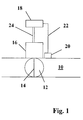
- a throttle valve 12 is used Control the performance of the internal combustion engine by the effective cross section of the intake manifold 10 by pivoting the throttle valve around it Axis 14 is enlarged or reduced.
- the throttle valve swivels 12 instead of an electric motor 16, which is controlled by a control device 18 is controlled via corresponding lines 24.
- the control unit 18 information such as position of the throttle valve, operating parameters such as intake manifold vacuum, speed and other information supplied to to open or close the throttle valve 12 depending on this information conclude.
- control signals in the form of a pulse train supplied to the electric motor in addition to the control signals, wherein the frequency of the pulse train can be so high that the electric motor 16th can no longer react mechanically and accordingly the throttle valve 12 no longer opens or closes, no trembling movements Throttle valve 12 take place more.
- a pendulum or tremor with no negative impact on engine operation and combustion processes can lead to the desired effect.
- a temperature sensor 20 provided the temperature on the wall of the suction pipe 10 detected and passed on to the control unit 18 via a line 22.
- the Temperature sensor can also be used in a detection of temperature changing electrical quantities exist, so that a separate component is superfluous.
- the winding resistance of the electric motor can be used as a measure of the temperature.
- the contribution of engine temperature sensor and / or air temperature sensor is possible. In this way, a control loop can be achieved which heats up limited the electric motor 16 to the necessary extent.
Landscapes
- Engineering & Computer Science (AREA)
- Chemical & Material Sciences (AREA)
- Combustion & Propulsion (AREA)
- Mechanical Engineering (AREA)
- General Engineering & Computer Science (AREA)
- Analytical Chemistry (AREA)
- Control Of Throttle Valves Provided In The Intake System Or In The Exhaust System (AREA)
- Lift Valve (AREA)
- Details Of Valves (AREA)
- Lubrication Details And Ventilation Of Internal Combustion Engines (AREA)
Description
Claims (6)
- Verfahren zur Beheizung eines über einen Elektromotor (16) angesteuerten Drosselklappenstutzens (10) in einer Brennkraftmaschine, dadurch gekennzeichnet, daß die Verlustleistung des die Drosselklappe (12) betätigenden Elektromotors (16) erhöht wird.
- Verfahren nach Anspruch 1, dadurch gekennzeichnet, daß der Elektromotor (16) mit einer Impulsfolge angesteuert wird, deren Frequenz derart gewählt ist, daß der Elektromotor (16) nicht mechanisch reagiert.
- Verfahren nach Anspruch 1, dadurch gekennzeichnet, daß der Elektromotor (16) mit einer Impulsfolge angesteuert wird, deren Frequenz derart gewählt ist, daß die Bewegungen der Drosselklappe (12) keinen Einfluß auf den Verbrennungsablauf haben.
- Verfahren nach Anspruch 1 bis 3, dadurch gekennzeichnet, daß die Ansteuerung abhängig von der Außentemperatur gewählt wird.
- Verfahren nach einem der vorhergehenden Ansprüche, dadurch gekennzeichnet, daß der Bewegungsverlauf der Drosselklappe (12) lagegeregelt ist.
- Saugrohr für eine Brennkraftmaschine mit einer über einen Elektromotor (16) angesteuerten Drosselklappe, wobei der Elektromotor (16) und die Drosselklappe (12) in räumlicher Nähe zueinander angeordnet sind und wobei eine Wärmebrücke zwischen Elektromotor (16) und Drosselklappe (12) vorgesehen ist, dadurch gekennzeichnet, daß der Elektromotor (16) zur Beheizung des Drosselklappenstutzens über sein Steuergerät (18) mit einer die Verlustleistung des Elektromotors (16) erhöhenden Impulsfolge beaufschlagt ist.
Applications Claiming Priority (2)
| Application Number | Priority Date | Filing Date | Title |
|---|---|---|---|
| DE19505407 | 1995-02-17 | ||
| DE19505407A DE19505407A1 (de) | 1995-02-17 | 1995-02-17 | Verfahren zur Beheizung eines Drosselklappenstutzens |
Publications (2)
| Publication Number | Publication Date |
|---|---|
| EP0727573A1 EP0727573A1 (de) | 1996-08-21 |
| EP0727573B1 true EP0727573B1 (de) | 2000-04-26 |
Family
ID=7754257
Family Applications (1)
| Application Number | Title | Priority Date | Filing Date |
|---|---|---|---|
| EP96101499A Expired - Lifetime EP0727573B1 (de) | 1995-02-17 | 1996-02-02 | Verfahren zur Beheizung eines Drosselklappenstutzens und Saugrohr für eine Brennkraftmaschine |
Country Status (5)
| Country | Link |
|---|---|
| US (1) | US5680850A (de) |
| EP (1) | EP0727573B1 (de) |
| JP (1) | JPH08240130A (de) |
| DE (2) | DE19505407A1 (de) |
| ES (1) | ES2145333T3 (de) |
Families Citing this family (2)
| Publication number | Priority date | Publication date | Assignee | Title |
|---|---|---|---|---|
| US6467468B1 (en) | 1999-11-01 | 2002-10-22 | Siemens Vdo Automotive Inc. | Throttle position sensor that heats the throttle shaft |
| DE102014211935A1 (de) | 2014-06-23 | 2015-12-24 | Robert Bosch Gmbh | Verfahren zum Betreiben einer Reagenzmittel-Dosiervorrichtung, Vorrichtung zur Durchführung des Verfahrens, Computer-Programm und Computer-Programmprodukt |
Family Cites Families (16)
| Publication number | Priority date | Publication date | Assignee | Title |
|---|---|---|---|---|
| DE476688C (de) * | 1927-09-22 | 1929-06-03 | Rolf Hofgaard | Elektrische Rechenmaschine |
| DE1927463U (de) * | 1963-07-27 | 1965-11-18 | Ford Werke Ag | Drosselklappe fuer vergaser von kraftfahrzeugen. |
| JPS60190626A (ja) * | 1984-03-09 | 1985-09-28 | Hitachi Ltd | 絞弁制御装置 |
| JPS61169477U (de) * | 1985-04-04 | 1986-10-21 | ||
| US4854283A (en) * | 1986-11-28 | 1989-08-08 | Nippondenso Co., Ltd. | Throttle valve control apparatus |
| JP2506831B2 (ja) * | 1987-10-28 | 1996-06-12 | 株式会社日立製作所 | 内燃機関のスロツトルアクチユエ―タ |
| DE3743309A1 (de) * | 1987-12-21 | 1989-06-29 | Bosch Gmbh Robert | Verfahren und einrichtung zur erkennung und lockerung verklemmter stellelemente |
| US5255653A (en) * | 1989-04-17 | 1993-10-26 | Lucas Industries Public Limited Company | Engine throttle control system |
| JPH0361636A (ja) * | 1989-07-27 | 1991-03-18 | Honda Motor Co Ltd | 車載エンジンの制御弁制御装置 |
| JPH0378537A (ja) * | 1989-08-21 | 1991-04-03 | Aisin Seiki Co Ltd | スロットルボデーの温水加熱装置 |
| EP0450787A3 (en) * | 1990-04-04 | 1992-09-09 | Lucas Industries Public Limited Company | Engine control system and method |
| DE4026785A1 (de) * | 1990-08-24 | 1992-02-27 | Bosch Gmbh Robert | Stellvorrichtung |
| DE9013980U1 (de) * | 1990-10-08 | 1992-02-06 | Hella KG Hueck & Co., 59557 Lippstadt | Drosselklappenstutzen für eine Brennkraftmaschine, insbesondere für Kraftfahrzeuge |
| DE4223933A1 (de) * | 1992-07-21 | 1994-01-27 | Bosch Gmbh Robert | Drosselvorrichtung für eine Brennkraftmaschine |
| DE4228485A1 (de) * | 1992-08-27 | 1994-03-03 | Bosch Gmbh Robert | Drosselvorrichtung für eine Brennkraftmaschine |
| DE4234460A1 (de) * | 1992-10-13 | 1994-04-14 | Hella Kg Hueck & Co | Einrichtung zur Steuerung der Frischgasmenge einer Brennkraftmaschine |
-
1995
- 1995-02-17 DE DE19505407A patent/DE19505407A1/de not_active Withdrawn
-
1996
- 1996-02-02 EP EP96101499A patent/EP0727573B1/de not_active Expired - Lifetime
- 1996-02-02 DE DE59605013T patent/DE59605013D1/de not_active Expired - Lifetime
- 1996-02-02 ES ES96101499T patent/ES2145333T3/es not_active Expired - Lifetime
- 1996-02-16 US US08/602,338 patent/US5680850A/en not_active Expired - Fee Related
- 1996-02-19 JP JP8029776A patent/JPH08240130A/ja active Pending
Also Published As
| Publication number | Publication date |
|---|---|
| JPH08240130A (ja) | 1996-09-17 |
| US5680850A (en) | 1997-10-28 |
| DE19505407A1 (de) | 1996-08-22 |
| ES2145333T3 (es) | 2000-07-01 |
| EP0727573A1 (de) | 1996-08-21 |
| DE59605013D1 (de) | 2000-05-31 |
Similar Documents
| Publication | Publication Date | Title |
|---|---|---|
| DE102008041876B4 (de) | Ventilöffnungs- und Schliesssteuergerät | |
| DE102016219369B4 (de) | Steuersystem für Verbrennungsmotor | |
| DE69324338T2 (de) | Einrichtung zur Steuerung der Position eines Betätigungsgliedes | |
| DE60216696T2 (de) | Steuersystem eines Stellglieds | |
| DE102006040667B3 (de) | Waste-Gate-Aktuator für einen Abgasturbolader | |
| WO1999032764A1 (de) | Verfahren zur steuerung einer brennkraftmaschine | |
| DE102015120779B4 (de) | Vorrichtung zum Verbessern der Kühleffizienz eines Motorraums in einem Fahrzeug | |
| DE3741622A1 (de) | Verfahren zur steuerung einer einspritzvorrichtung | |
| EP1355052B1 (de) | Ladesystem für eine Brennkraftmaschine sowie Verfahren zu dessen Regelung | |
| DE112008002852T5 (de) | Steuerungsvorrichtung und Verfahren zur Steuerung eines an Fahrzeugen montierten Verbrennungsmotors | |
| DE3886331T2 (de) | Verfahren und System zur Steuerung des Radschlupfes eines Fahrzeugs. | |
| DE19732642A1 (de) | Einrichtung zum Steuern einer Brennkraftmaschine | |
| DE19848594C2 (de) | Elektrisch gesteuerte Drosselklappenvorrichtung | |
| DE102018211538A1 (de) | Verfahren zur Steuerung eines Aufladungssystems | |
| DE102006008785A1 (de) | Einrichtung zur Frischluftversorgung einer turboaufgeladenen Kolbenbrennkraftmaschine und Verfahren zum Betrieb derselben | |
| DE102008051817B4 (de) | Verfahren zum Betätigen eines Wastegateventils | |
| DE69926446T2 (de) | Steuervorrichtung für ein Stellorgan einer Brennkraftmaschine | |
| EP1853807A1 (de) | Verfahren zur spannungsgesteuerten leistungseinstellung der heizung einer abgassonde | |
| EP0727573A1 (de) | Verfahren zur Beheizung eines Drosselklappenstutzens | |
| EP0989292A2 (de) | Elektromotorisches Stellglied, insbesondere mit einer Drosselklappe | |
| EP3303799B1 (de) | Verfahren und steuervorrichtung zum betreiben einer antriebsvorrichtung | |
| DE19801387A1 (de) | Abgasrückführventil | |
| DE10261278A1 (de) | Verfahren und Vorrichtung zur Drehmomentänderung | |
| EP3221172A1 (de) | Luftzufuhreinstellvorrichtung für ein kraftfahrzeug | |
| DE3719975A1 (de) | Regelsystem fuer eine aufgeladene brennkraftmaschine |
Legal Events
| Date | Code | Title | Description |
|---|---|---|---|
| PUAI | Public reference made under article 153(3) epc to a published international application that has entered the european phase |
Free format text: ORIGINAL CODE: 0009012 |
|
| AK | Designated contracting states |
Kind code of ref document: A1 Designated state(s): BE DE ES FR GB IT SE |
|
| 17P | Request for examination filed |
Effective date: 19960705 |
|
| 17Q | First examination report despatched |
Effective date: 19980925 |
|
| GRAG | Despatch of communication of intention to grant |
Free format text: ORIGINAL CODE: EPIDOS AGRA |
|
| GRAG | Despatch of communication of intention to grant |
Free format text: ORIGINAL CODE: EPIDOS AGRA |
|
| GRAH | Despatch of communication of intention to grant a patent |
Free format text: ORIGINAL CODE: EPIDOS IGRA |
|
| ITF | It: translation for a ep patent filed | ||
| GRAH | Despatch of communication of intention to grant a patent |
Free format text: ORIGINAL CODE: EPIDOS IGRA |
|
| GRAA | (expected) grant |
Free format text: ORIGINAL CODE: 0009210 |
|
| AK | Designated contracting states |
Kind code of ref document: B1 Designated state(s): BE DE ES FR GB IT SE |
|
| REF | Corresponds to: |
Ref document number: 59605013 Country of ref document: DE Date of ref document: 20000531 |
|
| ET | Fr: translation filed | ||
| REG | Reference to a national code |
Ref country code: ES Ref legal event code: FG2A Ref document number: 2145333 Country of ref document: ES Kind code of ref document: T3 |
|
| GBT | Gb: translation of ep patent filed (gb section 77(6)(a)/1977) |
Effective date: 20000629 |
|
| PLBE | No opposition filed within time limit |
Free format text: ORIGINAL CODE: 0009261 |
|
| STAA | Information on the status of an ep patent application or granted ep patent |
Free format text: STATUS: NO OPPOSITION FILED WITHIN TIME LIMIT |
|
| 26N | No opposition filed | ||
| REG | Reference to a national code |
Ref country code: GB Ref legal event code: IF02 |
|
| PGFP | Annual fee paid to national office [announced via postgrant information from national office to epo] |
Ref country code: SE Payment date: 20140224 Year of fee payment: 19 Ref country code: DE Payment date: 20140228 Year of fee payment: 19 |
|
| PGFP | Annual fee paid to national office [announced via postgrant information from national office to epo] |
Ref country code: BE Payment date: 20140225 Year of fee payment: 19 Ref country code: IT Payment date: 20140219 Year of fee payment: 19 Ref country code: FR Payment date: 20140224 Year of fee payment: 19 Ref country code: ES Payment date: 20140212 Year of fee payment: 19 |
|
| PGFP | Annual fee paid to national office [announced via postgrant information from national office to epo] |
Ref country code: GB Payment date: 20140224 Year of fee payment: 19 |
|
| PG25 | Lapsed in a contracting state [announced via postgrant information from national office to epo] |
Ref country code: BE Free format text: LAPSE BECAUSE OF NON-PAYMENT OF DUE FEES Effective date: 20150228 |
|
| REG | Reference to a national code |
Ref country code: DE Ref legal event code: R119 Ref document number: 59605013 Country of ref document: DE |
|
| REG | Reference to a national code |
Ref country code: SE Ref legal event code: EUG |
|
| GBPC | Gb: european patent ceased through non-payment of renewal fee |
Effective date: 20150202 |
|
| REG | Reference to a national code |
Ref country code: FR Ref legal event code: ST Effective date: 20151030 |
|
| PG25 | Lapsed in a contracting state [announced via postgrant information from national office to epo] |
Ref country code: SE Free format text: LAPSE BECAUSE OF NON-PAYMENT OF DUE FEES Effective date: 20150203 |
|
| PG25 | Lapsed in a contracting state [announced via postgrant information from national office to epo] |
Ref country code: IT Free format text: LAPSE BECAUSE OF NON-PAYMENT OF DUE FEES Effective date: 20150202 |
|
| PG25 | Lapsed in a contracting state [announced via postgrant information from national office to epo] |
Ref country code: DE Free format text: LAPSE BECAUSE OF NON-PAYMENT OF DUE FEES Effective date: 20150901 Ref country code: GB Free format text: LAPSE BECAUSE OF NON-PAYMENT OF DUE FEES Effective date: 20150202 |
|
| PG25 | Lapsed in a contracting state [announced via postgrant information from national office to epo] |
Ref country code: FR Free format text: LAPSE BECAUSE OF NON-PAYMENT OF DUE FEES Effective date: 20150302 |
|
| REG | Reference to a national code |
Ref country code: ES Ref legal event code: FD2A Effective date: 20160329 |
|
| PG25 | Lapsed in a contracting state [announced via postgrant information from national office to epo] |
Ref country code: ES Free format text: LAPSE BECAUSE OF NON-PAYMENT OF DUE FEES Effective date: 20150203 |