EP0727619A2 - Anordnung für die Zuführung von Primärluft zu einem atmosphärischen Gasbrenner über einer Kochplatte aus Glaskeramik - Google Patents
Anordnung für die Zuführung von Primärluft zu einem atmosphärischen Gasbrenner über einer Kochplatte aus Glaskeramik Download PDFInfo
- Publication number
- EP0727619A2 EP0727619A2 EP95120532A EP95120532A EP0727619A2 EP 0727619 A2 EP0727619 A2 EP 0727619A2 EP 95120532 A EP95120532 A EP 95120532A EP 95120532 A EP95120532 A EP 95120532A EP 0727619 A2 EP0727619 A2 EP 0727619A2
- Authority
- EP
- European Patent Office
- Prior art keywords
- hotplate
- arrangement according
- assembly
- adjacent
- primary air
- Prior art date
- Legal status (The legal status is an assumption and is not a legal conclusion. Google has not performed a legal analysis and makes no representation as to the accuracy of the status listed.)
- Granted
Links
Images


Classifications
-
- F—MECHANICAL ENGINEERING; LIGHTING; HEATING; WEAPONS; BLASTING
- F24—HEATING; RANGES; VENTILATING
- F24C—DOMESTIC STOVES OR RANGES ; DETAILS OF DOMESTIC STOVES OR RANGES, OF GENERAL APPLICATION
- F24C15/00—Details
- F24C15/10—Tops, e.g. hot plates; Rings
-
- F—MECHANICAL ENGINEERING; LIGHTING; HEATING; WEAPONS; BLASTING
- F24—HEATING; RANGES; VENTILATING
- F24C—DOMESTIC STOVES OR RANGES ; DETAILS OF DOMESTIC STOVES OR RANGES, OF GENERAL APPLICATION
- F24C3/00—Stoves or ranges for gaseous fuels
- F24C3/08—Arrangement or mounting of burners
- F24C3/085—Arrangement or mounting of burners on ranges
Definitions
- the invention relates to an arrangement for supplying primary air to an atmospheric gas burner, which is positioned above a continuous, flat hotplate made of glass ceramic, which is only broken in the area of the burner and operating element feedthrough, which is held as an assembly by means of a frame construction. and which form a cooking device together with other customary assemblies.
- the invention is therefore based on the object of presenting an arrangement for a primary air supply for atmospheric gas burners which has a sufficiently large area for air supply and which can also be easily integrated into a built-in hob which does not allow air supply, in particular from below, through the floor assembly . It should be possible to assemble the arrangement for the air supply easily and with little expenditure of time, material and costs, without having to be restricted to a special device or to a gas burner type.
- the object of the invention is achieved in that in the plane of the hotplate, along at least one of the boundary sides of the hotplate, a sufficiently wide distance for an adequate primary air supply to the gas burner is kept from an assembly of the cooking appliance adjacent to the hotplate, in which a device is inserted which allows air access, which is tightly and elastically connected to the hotplate and / or to the adjacent assembly, and which prevents the entry of liquid into parts of the cooking device lying below the level of the hotplate.
- the assembly which is adjacent to the hotplate and is arranged at a distance is a plate comprising the switch and control elements, which can be made of metal, glass ceramic or glass.
- the plate or the switch part is at an angle to the plane of the hotplate.
- the switch part gets z. B. a slight inclination forward, which allows the user an improved view of the controller position.
- the air supply can also be formed together with the frame if the assembly which is adjacent to the hotplate and is arranged at a distance is the metallic frame construction.
- the device which fits precisely, in particular by means of spacers into the cutout, which is formed by the distance between the hotplate and the adjacent assembly, on one side, on both sides or all around, is made of metal and the access to the opening of the cutout formed by the distance is by means of this device increased above the level of the hotplate level.
- the device can have a hood-shaped one-sided bend covering the opening at a distance. This prevents or reduces dirt and dust from above and also offers an attractive appearance.
- the device can be designed as, in particular, a laterally slotted or perforated tube into which an inner tube, which is provided with a continuous slot or with openings and rotatable against the outer tube, is introduced.
- the cutout which is formed by the distance between the hotplate and the adjacent assembly, z. B. can be completely closed during cleaning work.
- FIGS. 1 to 5 with the associated exemplary embodiments are intended to further illustrate the invention.
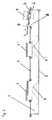
- Figure 1 shows a built-in hob 1 with a trough-shaped base plate 5, a continuous flat glass-ceramic hotplate 2 with two atmospheric gas burners 3, 3 ', which is broken only in the area of the burner and control element 4 passage.
- the gas burners 3, 3 ' are supported on the base plate 5 by means of spring plates 7, 7'.
- the air supply takes place here between the frame structure 6 and the glass ceramic cooktop 2, a device 9 made of stainless steel or black lacquered or anodized metal being provided here to protect the opening 8 from the ingress of liquid due to overflowing cookware or during cleaning, which is hood-shaped at a distance above the opening 8 between the hotplate 2 and the frame 6.
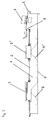
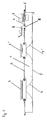
- FIGS. 2-5 each show further examples of the arrangement according to the invention for supplying primary air to atmospheric gas burners 3, 3 ′ over a glass ceramic plate 2.
Landscapes
- Engineering & Computer Science (AREA)
- Chemical & Material Sciences (AREA)
- Combustion & Propulsion (AREA)
- Mechanical Engineering (AREA)
- General Engineering & Computer Science (AREA)
- Gas Burners (AREA)
- Cookers (AREA)
- Baking, Grill, Roasting (AREA)
- Combinations Of Kitchen Furniture (AREA)
Abstract
Description
- Die Erfindung betrifft eine Anordnung für die Zuführung von Primärluft zu einem atmosphärischen Gasbrenner, der über einer durchgehenden, ebenen, nur im Bereich der Brenner- und Bedienungselemente-Durchführung durchbrochenen Kochplatte aus Glaskeramik positioniert ist, die mittels einer Rahmenkonstruktion, als einer Baugruppe gehalten wird, und die zusammen mit weiteren üblichen Baugruppen ein Kochgerät bilden.
- Bei Standherden kann wie bisher die Primärluft-Versorgung über Lüftungsschlitze im Herd- oder Schalterblendenbereich sichergestellt werden.
Bei Einbaukochfeldern ist jedoch eine Luftversorgung von unten über Aussparungen im Bodenblech nicht möglich, da sonst erhebliche Einschränkungen beim Einbau erforderlich wären. - Der Erfindung liegt daher die Aufgabe zugrunde, eine Anordnung für eine Primärluftzuführung für atmosphärische Gasbrenner vorzustellen, die eine genügend große Fläche zur Luftzuführung besitzt und die auch in ein Einbaukochfeld, das eine Luftversorgung, insbesondere von unten durch die Bodengruppe nicht ermöglicht, problemlos integriert werden kann. Dabei soll die Montage der Anordnung für die Luftzuführung einfach und mit geringem Aufwand an Zeit, Material und Kosten möglich sein, ohne sich dabei auf ein spezielles Gerät bzw. auf einen Gasbrennertyp beschränken zu müssen.
- Die Aufgabe nach der Erfindung wird dadurch gelöst, daß in der Ebene der Kochplatte, entlang mindestens einer der Begrenzungsseiten der Kochplatte, ein für eine ausreichende Primärluftzufuhr zum Gasbrenner genügend breiter Abstand zu einer der Kochplatte benachbarten Baugruppe des Kochgerätes gehalten ist, in den eine Vorrichtung eingesetzt ist, die den Luftzutritt ermöglicht, die mit der Kochplatte und/oder mit der benachbarten Baugruppe dicht und elastisch verbunden ist, und die den Zutritt von Flüssigkeit in, unter der Ebene der Kochplatte liegende Teile des Kochgeräts verhindert.
- Wird die Luftzuführung zwischen der Glaskeramik-Kochplatte und einer benachbarten Baugruppe angeordnet, so ergeben sich folgende zusätzlichen Anforderungen:
- es muß eine gegen Flüssigkeiten, z.B. Überkochgut dichte Verbindung zwischen Glaskeramik und der Baugruppe gegeben sein,
- es darf keine mechanisch starre Verbindung zwischen Glaskeramik-Kochplatte und der Anordnung für die Luftzuführung und der benachbarten Baugruppe auftreten,
- es muß ein auf die verwendeten Brenner abgestimmter Mindestquerschnitt für den Lufteintritt vorhanden sein (ca. 700 mm2/Brenner).
- Dabei ist in bevorzugter Ausgestaltung der Erfindung die der Kochplatte benachbarte, im Abstand angeordnete Baugruppe eine, die Schalter- und Kontrollelemente umfassende Platte, die aus Metall, Glaskeramik oder Glas bestehen kann.
- Es hat sich als zusätzlich vorteilhaft erwiesen, wenn die Platte bzw. das Schalterteil in einem Winkel zur Ebene der Kochplatte steht.
Dabei bekommt das Schalterteil z. B. eine leichte Neigung nach vorn, was dem Benutzer eine verbesserte Sicht auf die Reglerstellung ermöglicht. Schließlich kann die Luftzuführung auch mit dem Rahmen zusammen gebildet werden, wenn die der Kochplatte benachbarte, beabstandet angeordnete Baugruppe die metallische Rahmenkonstruktion ist. - Die Vorrichtung, die passgenau, insbesondere mittels Abstandshaltern in den Ausschnitt, der durch den Abstand zwischen Kochplatte und benachbarter Baugruppe gebildet wird, einseitig, beidseitig oder umlaufend eingesetzt wird, besteht aus Metall und der Zugang zur Öffnung des, durch den Abstand gebildeten Ausschnitts ist mittels dieser Vorrichtung über das Niveau der Ebene der Kochplatte erhöht.
- Es ist wichtig, daß ein gewisses Überlaufvolumen aufgefangen werden kann, ohne daß es durch die Luftzuführung in den Muldeninnenraum gelangt, da sonst Verschmutzungen und Schäden an der unterliegenden Elektrik und/oder Elektronik auftreten können.
Auch bei der Pflege und Reinigung der Kochplatte ist es notwendig jeden Durchtritt von flüssigen Medien z. B. von Reinigungsmaterialien zu vermeiden.
Dabei ist es vorteilhaft, den Zugang zur Öffnung ca. 3 - 5 mm, über das Niveau der Kochplattenebene zu erhöhen.
Zusätzlich kann die Vorrichtung eine die Öffnung im Abstand überdeckende haubenförmige einseitige Umbiegung aufweisen.
Dies verhindert oder reduziert den Schmutz- und Staubbefall von oben und bietet auch eine ansprechende Optik. - Als weitere Möglichkeit kann die Vorrichtung als, insbesondere seitlich geschlitztes oder perforiertes Rohr ausgebildet sein, in das ein, mit einem durchgehenden Schlitz oder mit Durchbrechungen versehenes, gegen das Außenrohr drehbares Innenrohr eingebracht ist.
- Hierdurch ist es besonders leicht möglich, die Menge der zuzuführenden Luft und die Ansaugrichtung zu regeln und einzustellen, wobei mittels dieser Vorrichtungen der Ausschnitt, der durch den Abstand zwischen Kochplatte und benachbarter Baugruppe gebildet wird, z. B. bei Reinigungsarbeiten vollkommen verschlossen werden kann.
- Als besonders vorteilhaft hat es sich erwiesen, die Vorrichtung mittels eines Silikonklebers dicht und elastisch zwischen der Kochplatte und/oder der benachbarten Baugruppe zu verkleben und zu positionieren.
- Die folgenden Figuren 1 bis 5 mit den dazugehörigen Ausführungsbeispielen sollen die Erfindung weiter veranschaulichen.
- Es zeigen:
- Fig. 1:
- Primärluftzufuhr nach der Erfindung, zwischen dem Rahmen aus Blech und der Kochplatte aus Glaskeramik
- Fig. 2:
- Primärluftzufuhr zwischen der Glaskeramik-Kochplatte und einem Glaskeramik-Schalterteil, wobei das Schalterteil hier schräggestellt ist
- Fig. 3:
- Primärluftzufuhr zwischen der Glaskeramik-Kochplatte und einem Schalterteil aus Blech, das schräggestellt ist
- Fig. 4:
- Primärluftzufuhr zwischen Glaskeramik-Kochplatte und Glaskeramik-Schalterteil, wobei das Schalterteil in der Ebene der Kochplatte angeordnet ist
- Fig. 5:
- Primärluftzufuhr zwischen Glaskeramik-Kochplatte und einem Schalterteil aus Blech, wobei das Schalterteil in der Ebene der Kochplatte angeordnet ist.
- Figur 1 zeigt eine Einbau-Kochmulde 1 mit einem wannenförmigen Bodenblech 5, einer durchgehenden ebenen Glaskeramik-Kochplatte 2 mit zwei atmosphärischen Gasbrennern 3, 3', die nur im Bereich der Brenner- und Bedienungselement 4-Durchführung durchbrochen ist. Die Gasbrenner 3, 3' stützen sich mittels Federblechen 7, 7' auf dem Bodenblech 5 ab.
- Die Luftzufuhr erfolgt hier zwischen der Rahmenkonstruktion 6 und der Glaskeramikkochfläche 2 wobei hier zum Schutz der Öffnung 8 vor Flüssigkeitseintritt durch überlaufendes Kochgut oder bei der Reinigung eine Vorrichtung 9 aus Edelstahl oder schwarz lackiertem oder eloxiertem Metall vorgesehen ist, die sich haubenförmig im Abstand über die Öffnung 8 zwischen der Kochplatte 2 und dem Rahmen 6 legt.
- Die Figuren 2 - 5 zeigen jeweils weitere Beispiele der erfindungsgemäßen Anordnung zur Primärluftzufuhr an atmosphärische Gasbrenner 3, 3' über einer Glaskeramikplatte 2.
Claims (12)
- Anordnung für die Zuführung von Primärluft zu einem atmosphärischen Gasbrenner, der über einer durchgehenden, ebenen, nur im Bereich der Brenner- und Bedienungselemente-Durchführung durchbrochenen Kochplatte aus Glaskeramik positioniert ist, die mittels einer Rahmenkonstruktion, als einer Baugruppe gehalten wird, und die zusammen mit weiteren üblichen Baugruppen ein Kochgerät bilden,
dadurch gekennzeichnet,
daß in der Ebene der Kochplatte, entlang mindestens einer der Begrenzungsseiten der Kochplatte, ein für eine ausreichende Primärluftzufuhr zum Gasbrenner genügend breiter Abstand zu einer der Kochplatte benachbarten Baugruppe des Kochgerätes gehalten ist, in den eine Vorrichtung eingesetzt ist, die den Luftzutritt ermöglicht, die mit der Kochplatte und/oder mit der benachbarten Baugruppe dicht und elastisch verbunden ist, und die den Zutritt von Flüssigkeit in, unter der Ebene der Kochplatte liegende Teile des Kochgeräts verhindert. - Anordnung nach Anspruch 1,
dadurch gekennzeichnet,
daß die der Kochplatte benachbarte, im Abstand angeordnete Baugruppe eine, die Schalter- und Kontrollelemente umfassende Platte ist. - Anordnung nach Anspruch 2,
dadurch gekennzeichnet,
daß die Platte aus Metall besteht. - Anordnung nach Anspruch 2,
dadurch gekennzeichnet,
daß die Platte aus Glaskeramik oder Glas besteht. - Anordnung nach den Ansprüchen 1 bis 4,
dadurch gekennzeichnet,
daß die Platte in einem Winkel zur Ebene der Kochplatte steht. - Anordnung nach Anspruch 1,
dadurch gekennzeichnet,
daß die der Kochplatte benachbarte, beabstandet angeordnete Baugruppe die metallische Rahmenkonstruktion ist. - Anordnung nach den Ansprüchen 1 bis 6,
dadurch gekennzeichnet,
daß die Vorrichtung, die passgenau, insbesondere auch mittels Abstandshaltern in den Ausschnitt, der durch den Abstand zwischen Kochplatte und benachbarter Baugruppe gebildet wird, einseitig, beidseitig oder umlaufend eingesetzt ist, aus Metall besteht und der Zugang zur Öffnung des, durch den Abstand gebildeten Ausschnitts, mittels dieser Vorrichtung über das Niveau der Ebene der Kochplatte erhöht ist. - Anordnung nach Anspruch 7,
dadurch gekennzeichnet,
daß die Vorrichtung eine die Öffnung im Abstand überdeckende haubenförmige, einseitige Umbiegung aufweist. - Anordnung nach Anspruch 7,
dadurch gekennzeichnet,
daß die Vorrichtung als, insbesondere seitlich geschlitztes oder perforiertes Rohr ausgebildet ist, in das ein, mit einem durchgehenden Schlitz oder mit Durchbrechungen versehenes, gegen das Außenrohr drehbares Innenrohr eingebracht ist. - Anordnung nach dem Anspruch 9,
dadurch gekennzeichnet,
daß die Menge der zuzuführenden Luft und die Ansaugrichtung mittels der Vorrichtung regel- und einstellbar ist. - Anordnung nach dem Anspruch 9,
dadurch gekennzeichnet,
daß mittels der Vorrichtung der Ausschnitt, der durch den Abstand zwischen Kochplatte und benachbarter Baugruppe gebildet wird dicht verschließbar ist. - Anordnung nach den Ansprüchen 1 bis 11,
dadurch gekennzeichnet,
daß die Vorrichtung mittels eines Silikonklebers dicht und elastisch zwischen der Kochplatte und/oder der benachbarten Baugruppe verklebt und positioniert ist.
Applications Claiming Priority (2)
| Application Number | Priority Date | Filing Date | Title |
|---|---|---|---|
| DE19505469A DE19505469C1 (de) | 1995-02-17 | 1995-02-17 | Anordnung für die Zuführung von Primärluft zu einem atmosphärischen Gasbrenner über einer Kochplatte aus Glaskeramik |
| DE19505469 | 1995-02-17 |
Publications (3)
| Publication Number | Publication Date |
|---|---|
| EP0727619A2 true EP0727619A2 (de) | 1996-08-21 |
| EP0727619A3 EP0727619A3 (de) | 1997-05-21 |
| EP0727619B1 EP0727619B1 (de) | 1998-10-21 |
Family
ID=7754297
Family Applications (1)
| Application Number | Title | Priority Date | Filing Date |
|---|---|---|---|
| EP95120532A Expired - Lifetime EP0727619B1 (de) | 1995-02-17 | 1995-12-27 | Anordnung für die Zuführung von Primärluft zu einem atmosphärischen Gasbrenner über einer Kochplatte aus Glaskeramik |
Country Status (6)
| Country | Link |
|---|---|
| US (1) | US5653219A (de) |
| EP (1) | EP0727619B1 (de) |
| JP (1) | JP3605218B2 (de) |
| AT (1) | ATE172529T1 (de) |
| DE (2) | DE19505469C1 (de) |
| ES (1) | ES2123201T3 (de) |
Cited By (1)
| Publication number | Priority date | Publication date | Assignee | Title |
|---|---|---|---|---|
| EP0964203A1 (de) | 1998-06-09 | 1999-12-15 | SABAF S.p.A. | Gasbrenner |
Families Citing this family (25)
| Publication number | Priority date | Publication date | Assignee | Title |
|---|---|---|---|---|
| DE19703301C2 (de) * | 1997-01-30 | 2000-06-08 | Schott Glas | Gaskochgerät |
| DE19733242C1 (de) * | 1997-08-01 | 1998-10-15 | Schott Glas | Gas-Kochfeld mit einem plattenförmigen Formkörper aus sprödbrüchigem Material |
| DE19742792C1 (de) * | 1997-09-27 | 1998-11-19 | Schott Glas | Anordnung eines atmosphärischen Gasbrenners in einer Kochmulde mit einer Kochfläche aus Glaskeramik |
| DE19757731A1 (de) * | 1997-12-23 | 1999-06-24 | Bosch Siemens Hausgeraete | Gasbrenneranordnung für Kochstellen |
| DE19820444A1 (de) * | 1998-05-07 | 1999-11-11 | Bsh Bosch Siemens Hausgeraete | Federnde Gas-Brenner-Lagerung |
| DE19861078C2 (de) | 1998-09-29 | 2001-05-03 | Schott Glas | Gaskochgerät |
| DE19844551C2 (de) | 1998-09-29 | 2001-04-26 | Schott Glas | Gaskochgerät |
| DE19905670A1 (de) | 1998-12-16 | 2000-09-07 | Schott Glas | Kochgerät |
| US6173708B1 (en) | 1999-11-15 | 2001-01-16 | Maytag Corporation | Gas burner mounting assembly for appliance with ceramic based cooktop |
| DE20016145U1 (de) * | 2000-09-18 | 2001-01-18 | Schott Glas, 55122 Mainz | Kochfeld mit mindestens einem atmosphärischen Gasbrenner |
| DE10056987C1 (de) * | 2000-11-17 | 2002-06-20 | Bsh Bosch Siemens Hausgeraete | Gaskochgerät |
| US6410892B1 (en) | 2001-06-19 | 2002-06-25 | Bsh Home Appliances Corporation | Cooktop having a flat glass ceramic cooking surface |
| US6807962B2 (en) * | 2002-01-28 | 2004-10-26 | Schott Glas | Kitchen gas cooking stove with a glass-ceramic, glass, or ceramic top, a gas cooktop with a glass-ceramic, glass, or ceramic top, and a glass-ceramic, glass, or ceramic top of a cooking stove or cooktop with a venting structure thereon |
| DE10211520A1 (de) * | 2002-03-15 | 2003-09-25 | Bsh Bosch Siemens Hausgeraete | Glaskeramik-Kochfläche |
| US6729323B1 (en) | 2003-03-06 | 2004-05-04 | General Electric Company | Air-inlet assembly for a gas cooking appliance |
| ES2304826B1 (es) * | 2005-10-28 | 2009-06-26 | Bsh Electrodomesticos España, S.A. | Fuego de cocina de gas. |
| CN101206040B (zh) * | 2006-12-22 | 2013-05-01 | 博西华电器(江苏)有限公司 | 燃气灶以及用于燃气灶的面板 |
| ES2387152B1 (es) * | 2008-09-22 | 2013-07-17 | Bsh Electrodomesticos España, S.A | Bandeja de coccion a gas |
| DE102008043890A1 (de) * | 2008-11-19 | 2010-05-20 | BSH Bosch und Siemens Hausgeräte GmbH | Gaskochmulde mit versenkbarer Lüftungseinrichtung |
| IT1401158B1 (it) * | 2010-07-28 | 2013-07-12 | Smeg Spa | Piano cottura |
| DE102011081351A1 (de) | 2011-08-23 | 2013-02-28 | BSH Bosch und Siemens Hausgeräte GmbH | Gaskochfeld |
| US9513012B2 (en) | 2013-12-11 | 2016-12-06 | Whirlpool Corporation | Additional primary air access for surface gas burners |
| ES2584918B1 (es) * | 2015-03-31 | 2017-07-11 | Bsh Electrodomésticos España, S.A. | Quemador de gas y campo de cocción a gas |
| US10413124B2 (en) * | 2016-03-08 | 2019-09-17 | Portable Kitchens, Inc. | Barbecue grill and smoker |
| US11287138B2 (en) * | 2018-12-10 | 2022-03-29 | Bsh Home Appliances Corporation | Cooking appliance with top breathing burner having bottom breathing assist through top sheet |
Family Cites Families (5)
| Publication number | Priority date | Publication date | Assignee | Title |
|---|---|---|---|---|
| GB2149089B (en) * | 1983-11-03 | 1987-06-03 | Thorn Emi Domestic Appliances | Gas cooking hob |
| US5046477A (en) * | 1990-12-28 | 1991-09-10 | Amana Refrigeration Inc. | Gas cook-top with glass top |
| DE4233470A1 (de) * | 1992-10-05 | 1994-04-07 | Bosch Siemens Hausgeraete | Kochmulde |
| DE4325168C1 (de) * | 1993-07-27 | 1995-04-06 | Schott Glaswerke | Vorgefertigte Kochflächeneinheit zum verklebungsfreien Einbau in eine Rahmenkonstruktion oder in einen Ausschnitt |
| DE4339877A1 (de) * | 1993-11-23 | 1995-05-24 | Licentia Gmbh | Einbau-Glaskeramikkochplatte mit mehreren induktionsbeheizten Kochstellen |
-
1995
- 1995-02-17 DE DE19505469A patent/DE19505469C1/de not_active Expired - Fee Related
- 1995-12-27 ES ES95120532T patent/ES2123201T3/es not_active Expired - Lifetime
- 1995-12-27 DE DE59503987T patent/DE59503987D1/de not_active Expired - Fee Related
- 1995-12-27 EP EP95120532A patent/EP0727619B1/de not_active Expired - Lifetime
- 1995-12-27 AT AT95120532T patent/ATE172529T1/de not_active IP Right Cessation
-
1996
- 1996-02-19 JP JP03088896A patent/JP3605218B2/ja not_active Expired - Fee Related
- 1996-02-20 US US08/604,011 patent/US5653219A/en not_active Expired - Fee Related
Cited By (1)
| Publication number | Priority date | Publication date | Assignee | Title |
|---|---|---|---|---|
| EP0964203A1 (de) | 1998-06-09 | 1999-12-15 | SABAF S.p.A. | Gasbrenner |
Also Published As
| Publication number | Publication date |
|---|---|
| EP0727619B1 (de) | 1998-10-21 |
| US5653219A (en) | 1997-08-05 |
| DE59503987D1 (de) | 1998-11-26 |
| ATE172529T1 (de) | 1998-11-15 |
| JPH08247463A (ja) | 1996-09-27 |
| EP0727619A3 (de) | 1997-05-21 |
| JP3605218B2 (ja) | 2004-12-22 |
| ES2123201T3 (es) | 1999-01-01 |
| DE19505469C1 (de) | 1996-02-08 |
Similar Documents
| Publication | Publication Date | Title |
|---|---|---|
| EP0727619B1 (de) | Anordnung für die Zuführung von Primärluft zu einem atmosphärischen Gasbrenner über einer Kochplatte aus Glaskeramik | |
| EP0856702B1 (de) | Gaskochgerät | |
| EP0996312A2 (de) | Anordnung eines einstückigen Formteils aus Glaskeramik, Glas oder Keramik | |
| DE19964489B4 (de) | Induktionskochfeld mit Kühlgebläse | |
| EP2147571B1 (de) | Kocheinheitsschutzvorrichtung | |
| EP1188990B1 (de) | Einbaukochmulde | |
| DE102020209243A1 (de) | Tür und Haushaltsgargerät | |
| DE60025033T2 (de) | Kochplatte | |
| EP2156706B1 (de) | Kochfeld | |
| DE19649047C2 (de) | Haushaltsgerät mit einer Bedienblende, die mit von vorne nicht sichtbaren Befestigungselementen befestigt ist | |
| EP0388728A2 (de) | Herdblende. | |
| DE3404199C2 (de) | Backofen | |
| DE19705656C2 (de) | Haushaltsherd | |
| EP0952404B1 (de) | Backofen mit Filtergehäuse | |
| DE29502661U1 (de) | Anordnung für die Zuführung von Primärluft zu einem atmosphärischen Gasbrenner über einer Kochplatte aus Glaskeramik | |
| EP1982116A2 (de) | Gargerät, insbesondere hocheinbau-gargerät, und verfahren zu dessen herstellung | |
| DE8905998U1 (de) | Gargerät | |
| EP1217303B1 (de) | Glaskeramikkochfeld mit verformter Glaskeramik | |
| DE29701494U1 (de) | Gaskochgerät | |
| EP1464898A1 (de) | Gargerät | |
| DE102007004625A1 (de) | Gargerät, insbesondere Hocheinbau-Gargerät, und Verfahren zu dessen Herstellung | |
| DE19903917B4 (de) | Backofen mit frontseitigem Kühlluftspalt | |
| EP1750060A2 (de) | Backofen | |
| DE19622581A1 (de) | Tür mit Befestigungshandgriff zum Verschließen der Ofenmuffel eines Back- und Bratofens | |
| DE19504156A1 (de) | Herdmulde |
Legal Events
| Date | Code | Title | Description |
|---|---|---|---|
| PUAI | Public reference made under article 153(3) epc to a published international application that has entered the european phase |
Free format text: ORIGINAL CODE: 0009012 |
|
| 17P | Request for examination filed |
Effective date: 19951227 |
|
| AK | Designated contracting states |
Kind code of ref document: A2 Designated state(s): AT DE ES FR GB NL |
|
| AX | Request for extension of the european patent |
Free format text: SI PAYMENT 951227 |
|
| RAX | Requested extension states of the european patent have changed |
Free format text: SI PAYMENT 951227 |
|
| PUAL | Search report despatched |
Free format text: ORIGINAL CODE: 0009013 |
|
| AK | Designated contracting states |
Kind code of ref document: A3 Designated state(s): AT DE ES FR GB NL |
|
| AX | Request for extension of the european patent |
Free format text: SI PAYMENT 951227 |
|
| 17Q | First examination report despatched |
Effective date: 19971008 |
|
| GRAG | Despatch of communication of intention to grant |
Free format text: ORIGINAL CODE: EPIDOS AGRA |
|
| GRAG | Despatch of communication of intention to grant |
Free format text: ORIGINAL CODE: EPIDOS AGRA |
|
| GRAH | Despatch of communication of intention to grant a patent |
Free format text: ORIGINAL CODE: EPIDOS IGRA |
|
| RAP1 | Party data changed (applicant data changed or rights of an application transferred) |
Owner name: CARL-ZEISS-STIFTUNG TRADING AS SCHOTT GLASWERKE Owner name: SCHOTT GLAS |
|
| GRAH | Despatch of communication of intention to grant a patent |
Free format text: ORIGINAL CODE: EPIDOS IGRA |
|
| RAP1 | Party data changed (applicant data changed or rights of an application transferred) |
Owner name: CARL-ZEISS-STIFTUNG TRADING AS SCHOTT GLAS Owner name: SCHOTT GLAS |
|
| GRAA | (expected) grant |
Free format text: ORIGINAL CODE: 0009210 |
|
| AK | Designated contracting states |
Kind code of ref document: B1 Designated state(s): AT DE ES FR GB NL |
|
| AX | Request for extension of the european patent |
Free format text: SI PAYMENT 951227 |
|
| REF | Corresponds to: |
Ref document number: 172529 Country of ref document: AT Date of ref document: 19981115 Kind code of ref document: T |
|
| REF | Corresponds to: |
Ref document number: 59503987 Country of ref document: DE Date of ref document: 19981126 |
|
| GBT | Gb: translation of ep patent filed (gb section 77(6)(a)/1977) |
Effective date: 19981118 |
|
| ET | Fr: translation filed | ||
| REG | Reference to a national code |
Ref country code: ES Ref legal event code: FG2A Ref document number: 2123201 Country of ref document: ES Kind code of ref document: T3 |
|
| PLBE | No opposition filed within time limit |
Free format text: ORIGINAL CODE: 0009261 |
|
| STAA | Information on the status of an ep patent application or granted ep patent |
Free format text: STATUS: NO OPPOSITION FILED WITHIN TIME LIMIT |
|
| 26N | No opposition filed | ||
| REG | Reference to a national code |
Ref country code: GB Ref legal event code: IF02 |
|
| PGFP | Annual fee paid to national office [announced via postgrant information from national office to epo] |
Ref country code: NL Payment date: 20041220 Year of fee payment: 10 |
|
| PGFP | Annual fee paid to national office [announced via postgrant information from national office to epo] |
Ref country code: AT Payment date: 20041222 Year of fee payment: 10 |
|
| PGFP | Annual fee paid to national office [announced via postgrant information from national office to epo] |
Ref country code: FR Payment date: 20041223 Year of fee payment: 10 |
|
| PGFP | Annual fee paid to national office [announced via postgrant information from national office to epo] |
Ref country code: GB Payment date: 20050110 Year of fee payment: 10 |
|
| PGFP | Annual fee paid to national office [announced via postgrant information from national office to epo] |
Ref country code: DE Payment date: 20050119 Year of fee payment: 10 |
|
| PGFP | Annual fee paid to national office [announced via postgrant information from national office to epo] |
Ref country code: ES Payment date: 20050128 Year of fee payment: 10 |
|
| PG25 | Lapsed in a contracting state [announced via postgrant information from national office to epo] |
Ref country code: GB Free format text: LAPSE BECAUSE OF NON-PAYMENT OF DUE FEES Effective date: 20051227 Ref country code: AT Free format text: LAPSE BECAUSE OF NON-PAYMENT OF DUE FEES Effective date: 20051227 |
|
| PG25 | Lapsed in a contracting state [announced via postgrant information from national office to epo] |
Ref country code: ES Free format text: LAPSE BECAUSE OF NON-PAYMENT OF DUE FEES Effective date: 20051228 |
|
| PG25 | Lapsed in a contracting state [announced via postgrant information from national office to epo] |
Ref country code: NL Free format text: LAPSE BECAUSE OF NON-PAYMENT OF DUE FEES Effective date: 20060701 Ref country code: DE Free format text: LAPSE BECAUSE OF NON-PAYMENT OF DUE FEES Effective date: 20060701 |
|
| GBPC | Gb: european patent ceased through non-payment of renewal fee |
Effective date: 20051227 |
|
| PG25 | Lapsed in a contracting state [announced via postgrant information from national office to epo] |
Ref country code: FR Free format text: LAPSE BECAUSE OF NON-PAYMENT OF DUE FEES Effective date: 20060831 |
|
| NLS | Nl: assignments of ep-patents |
Owner name: SCHOTT AG Effective date: 20060612 |
|
| NLV4 | Nl: lapsed or anulled due to non-payment of the annual fee |
Effective date: 20060701 |
|
| REG | Reference to a national code |
Ref country code: FR Ref legal event code: ST Effective date: 20060831 |
|
| REG | Reference to a national code |
Ref country code: ES Ref legal event code: FD2A Effective date: 20051228 |