EP0728497A2 - Zweikammer-Herzschrittmacher-System und Verfahren unter Verwendung der Detektion des Zusammenfalls von Reizungpulsen-Klopfen für die Verstellung der AV Verzögerung bei der Therapie von hypertrophischen obstruktiven Kardiomyopathien - Google Patents
Zweikammer-Herzschrittmacher-System und Verfahren unter Verwendung der Detektion des Zusammenfalls von Reizungpulsen-Klopfen für die Verstellung der AV Verzögerung bei der Therapie von hypertrophischen obstruktiven Kardiomyopathien Download PDFInfo
- Publication number
- EP0728497A2 EP0728497A2 EP96102387A EP96102387A EP0728497A2 EP 0728497 A2 EP0728497 A2 EP 0728497A2 EP 96102387 A EP96102387 A EP 96102387A EP 96102387 A EP96102387 A EP 96102387A EP 0728497 A2 EP0728497 A2 EP 0728497A2
- Authority
- EP
- European Patent Office
- Prior art keywords
- ventricular
- fusion
- escape interval
- pacemaker
- wave
- Prior art date
- Legal status (The legal status is an assumption and is not a legal conclusion. Google has not performed a legal analysis and makes no representation as to the accuracy of the status listed.)
- Granted
Links
Images




Classifications
-
- A—HUMAN NECESSITIES
- A61—MEDICAL OR VETERINARY SCIENCE; HYGIENE
- A61N—ELECTROTHERAPY; MAGNETOTHERAPY; RADIATION THERAPY; ULTRASOUND THERAPY
- A61N1/00—Electrotherapy; Circuits therefor
- A61N1/18—Applying electric currents by contact electrodes
- A61N1/32—Applying electric currents by contact electrodes alternating or intermittent currents
- A61N1/36—Applying electric currents by contact electrodes alternating or intermittent currents for stimulation
- A61N1/362—Heart stimulators
- A61N1/3627—Heart stimulators for treating a mechanical deficiency of the heart, e.g. congestive heart failure or cardiomyopathy
-
- A—HUMAN NECESSITIES
- A61—MEDICAL OR VETERINARY SCIENCE; HYGIENE
- A61N—ELECTROTHERAPY; MAGNETOTHERAPY; RADIATION THERAPY; ULTRASOUND THERAPY
- A61N1/00—Electrotherapy; Circuits therefor
- A61N1/18—Applying electric currents by contact electrodes
- A61N1/32—Applying electric currents by contact electrodes alternating or intermittent currents
- A61N1/36—Applying electric currents by contact electrodes alternating or intermittent currents for stimulation
- A61N1/362—Heart stimulators
- A61N1/365—Heart stimulators controlled by a physiological parameter, e.g. heart potential
- A61N1/368—Heart stimulators controlled by a physiological parameter, e.g. heart potential comprising more than one electrode co-operating with different heart regions
- A61N1/3682—Heart stimulators controlled by a physiological parameter, e.g. heart potential comprising more than one electrode co-operating with different heart regions with a variable atrioventricular delay
Definitions
- This invention relates to cardiac pacing systems and methods generally and, in particular, to dual chamber cardiac pacing systems and methods for delivering ventricular pacing pulses synchronized to atrial signals so as to benefit patients with Hypertrophic Obstructive Cardiomyopathy.
- Hypertrophic Obstructive Cardiomyopathy is characterized by a narrowed left ventricular outflow tract (LVOT), which causes a significant increase in the subaortic pressure gradient.
- the narrowed LVOT is caused by an increased thickness of the interventricular septum which obstructs blood flow during systole, or at the time of cardiac output.
- a DDD pacemaker has electrical connections to both the atrium and the ventricle, senses electrical signals in both chambers of the patient's heart, and delivers atrial pacing stimuli in the absence of signals indicative of natural atrial contractions, and ventricular pacing stimuli in the absence of signals indicative of natural ventricular contractions.
- Such a dual chamber pacemaker maintains the AV synchrony of the heart by delivering ventricular pace pulses at a controlled AV interval following each atrial event.
- a ventricular pace pulse is delivered in timed synchrony with the sensed or paced atrial depolarization.
- Pacing the right ventricular apex before spontaneous atrio-ventricular conduction activates the left ventricle is understood to alter the ventricular septal activation pattern. This reduces leftward motion of the septum, thereby reducing the LVOT obstruction and subaortic pressure gradient.
- the literature uniformly acknowledges the potential advantages of synchronized A-V pacing for HOCM patients, stressing the importance of achieving ventricular capture. Causing "complete ventricular capture” is important to obtain the above-described septal movement, while selecting the longest AV delay that results in complete ventricular capture is important in order to maximize the atrial contribution to ventricular filling. See U.S. Application S.N. 08/214,933, filed March 17, 1994, Method and Apparatus For Dual Chamber Cardiac Pacing, assigned to Medtronic, Inc., and the literature articles referenced therein.
- the delivered pace pulse should provide "pre-excitation,” i.e., depolarization of the ventricular apex before the septum.
- the AV escape interval should be set at the longest duration that maintains ventricular capture at different exercise levels. See the above-cited McDonald article. It has been suggested that the AV escape interval which allows for maximal pre-excitation of the ventricle by the pacing pulse can be selected by determining the AV escape interval that produces the widest paced QRS complex duration. See “Impact of Dual Chamber Permanent Pacing in Patients With Obstructive Hypertrophic Cardiomyopathy With Symptoms Refractory to Verapamil and ⁇ -Adrenergic Blocker Therapy," by Fananapazir et al., Circulation , Vol. 8, No. 6, June 1992, pp. 2149-2161.
- the prior art techniques for synchronous pacing of HOCM patients recognize the necessity to periodically evaluate the AV delay, or AV escape interval.
- the patient's spontaneous atrio-ventricular conduction time generally will change with heart rate, i.e., from rest to exercise.
- simultaneous drug treatment such as beta blockers may also modify AV conduction time and require renewed evaluation of the AV delay. If the AV delay is adjusted to a value which is too short, in order to ensure complete ventricular capture, the atrial contribution to ventricular filling is compromised. However, if the AV escape interval is adjusted to too great a value, ventricular capture is compromised, and there may be episodes of no ventricular pacing or the ventricular pace may not contribute the best possible reduction of the LVOT obstruction.
- This invention provides an apparatus and method utilizing ventricular fusion beat detection as the basis for an automatic AV delay algorithm for dual chamber pacing therapy in patients with HOCM.
- the AV interval of a dual chamber pacemaker is set to substantially the same value as the natural conduction time, such that the ventricular pace pulse is generated at about the same time that the R-wave naturally occurs, there results a condition known as "fusion.”
- This condition is not necessarily harmful, but has been viewed as undesired because the energy of the pace pulse is wasted since the cardiac tissue is refractory and does not respond to the pace pulse.
- the resulting R-wave morphology is different from the morphology either of a natural QRS wave or one that results from full capture by the delivered pace pulse.
- This change in morphology includes a change in the frequency content of the R-wave and the T-wave. Further, the amplitude of the T-wave evoked by the pace pulse decreases substantially as fusion is achieved; the amplitude of the T-wave following natural ventricular depolarization (VS) is too low to be sensed by the T-wave sense amplifier.
- VS ventricular depolarization
- a pacemaker which monitors the T-wave response for an indication of when and as the AV delay approaches the value at which fusion occurs (AV fus ), which generally corresponds to the intrinsic PR interval (AVC) minus an offset.
- the pacemaker utilizes this information for adjusting the pacemaker AV escape interval (AV esc ) to deliver ventricular pace pulses at a time within a small range of values just before fusion would occur. Since a ventricular pace pulse that results in a fusion beat does not provide full capture, it is desired to use the onset of fusion as the dynamic upper limit of the range of AV esc used by the pacemaker.
- the pacemaker uses an algorithm which adjusts the AV delay within a range having an upper limit of AV fus , so as to maximize complete ventricular capture.
- the pacemaker is programmed to increase the AV delay until the onset of ventricular fusion is detected.
- AV esc is immediately shortened to a value which assures complete ventricular capture, following which AV esc is increased stepwise every beat until ventricular fusion is again detected.
- ventricular fusion As the control variable for adjusting AV esc , there is provided a continuously automatic adjustment of AV esc , capable of maintaining AV esc within a small dynamic range just less than the intrinsic AV conduction, with continuous capture by pace pulses except for the instance of quasi-complete or semi-complete capture at the onset of fusion.
- the pacemaker of this invention avoids the necessity of incurring sensed ventricular events or even multiple fusion beats, while providing an optimum AV delay for ventricular filling, thereby maximizing benefit of the pacing therapy for the HOCM patient.
- the driving variable for adjusting AV esc is T-wave detection.
- the apparatus of this invention monitors T-wave amplitude, and determines when such T-wave amplitude drops by a sufficient absolute or relative amount to indicate failure of T-wave detection, indicating fusion or onset of fusion.
- the pacemaker first institutes an aggressive decrease in AV esc , e.g., 20 ms, and thereafter follows a program for incrementing AV esc during successive pacemaker cycles, so as to return AV esc toward the prior observed value of AV fus .
- AV esc is increased by even shorter increments, thereby maximizing the number of pace pulses delivered just prior to the timing out of the intrinsic AV conduction interval.
- FIG. 1 is a perspective representation of the pacemaker system of this invention showing an implantable pacemaker connected to a patient's heart.
- FIG. 2 is a block diagram of the primary functional components of the pacemaker system and method of this invention.
- Figure 3A is a generalized flow diagram illustrating steps taken in synchronous pacing in accordance with this invention
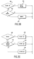
- Figure 3B is a simplified flow diagram illustrating a search step
- Figure 3C is a simplified flow diagram illustrating a specific routine for searching and adjusting AV esc .
- FIG. 4 is a generalized flow diagram for carrying out the adjust step in accordance with the preferred embodiment of this invention.
- Figure 5A is a timing diagram which illustrates the results of an algorithm for AV esc control which is based on the detection of ventricular senses;
- Figures 5B-5E are timing diagrams illustrating different search (scan) routines within the scope of this invention.
- FIG. 1 illustrates the external configuration of a dual chamber pacemaker 6, which is provided with a hermetically sealed enclosure 8, typically fabricated of biocompatible metal such as titanium.
- a connector block assembly 12 which receives electrical connectors located on the proximal ends of leads 14 and 16.
- Lead 16 is an atrial pacing lead, carrying two electrodes 20 and 21. Electrodes 20 and 21 are used both to sense atrial depolarizations and to deliver atrial pacing pulses. Atrial pacing pulses may be delivered between electrode 20 and electrode 21 or between electrode 21 and the housing 8 of the pacemaker 6. Sensing of atrial depolarizations may occur between electrode 20 and electrode 21 or between either of electrode 20 and 21 and the housing 8 of the pacemaker 6.
- lead 14 represents a ventricular bipolar pacing lead, carrying two electrodes 28 and 29.
- electrodes 28 and 29 are used to sense and pace the ventricle.
- Ventricular pacing may be accomplished between electrodes 29 and 28 or between electrode 29 and the conductive housing 8 of pacemaker 6.
- Sensing of ventricular signals, including depolarizations (QRS-waves) and repolarizations (T-waves) may be accomplished between electrodes 29 and 28 or between either of electrodes 29 and 28 and the housing 8 of the pacemaker 6.
- the preferred embodiments of the pacemaker 6 operate in a DDD or DDDR pacing mode, wherein pacing pulses are delivered to both atrium and ventricle and wherein atrial and ventricular depolarizations are both effective to inhibit delivery of the next scheduled pacing pulse in the chamber in which they are detected.
- DDDR may be indicated for patients that have drug-induced chronotropic incompetence.
- DDD or DDDR mode is expected to be the mode most widely used to practice the present invention.
- FIG 2 is a block functional diagram of the pacemaker illustrated in Figure 1, as connected to a human heart 10.
- the circuitry illustrated is all located within the conductive housing or can 8 of the pacemaker, as illustrated in Figure 1, and the bipolar leads 14 and 16 are illustrated schematically as coupled directly to the circuit. However, of course, in the actual device they would be coupled by means of removable electrical connectors inserted in the connector block 12, as illustrated in Figure 1.
- the pacemaker is divided generally into a microcomputer circuit 302 and a pacing circuit 320.
- a pulse generator circuit 340 includes a ventricular pulse generator circuit coupled to the heart 10 by means of electrodes 29 and 28 on lead 14, as well as an atrial pulse generator circuit coupled to the heart 10 by means of atrial electrodes 20 and 21, located on lead 16.
- pacing circuit 320 includes atrial and ventricular sense amplifiers in sense amplifier circuit 360, coupled to the atrium and ventricle by means of leads 14 and 16 as well.
- the ventricular sense amplifier provides for separate detection and identification of QRS-wave and T-wave signals, in a known manner.
- the output circuit 340 and sense amplifier circuit 360 may contain pulse generators and sense amplifiers corresponding to any of those presently employed in commercially marketed cardiac pacemakers.
- Digital controller/timer circuit 300 which includes a set of timers and associated logic.
- Digital controller/timer circuit 330 defines the basic pacing interval of the device, which may take the form of an A-A escape interval initiated on atrial sensing or pacing and triggering atrial pacing at the expiration thereof, or may take the form of a V-V escape interval, initiated on ventricular sensing or pacing and triggering ventricular pulse pacing at the expiration thereof.
- Digital controller/timer circuit 330 similarly defines the A-V escape interval, AV esc , discussed in detail below. The specific values of the intervals defined are controlled by the microcomputer circuit 302 by means of data and control bus 306.
- Sensed atrial depolarizations are communicated to the digital controller/timer circuit 330 on A event line 352; ventricular depolarizations (QRS-waves) are communicated to the digital controller/timer circuit 330 on V event line 354; and ventricular repolarizations (T-waves) are connected to circuit 330 on T-wave line 353.
- digital controller/timer circuit 330 In order to trigger generation of a ventricular pacing pulse, digital controller/timer circuit 330 generates a trigger signal on V trig line 342. Similarly, in order to trigger an atrial pacing pulse, digital controller/timer circuit 330 generates a trigger pulse on a trig line 344.
- Digital controller/timer circuit 330 also defines time intervals for controlling operation of the sense amplifiers in sense amplifier circuit 360.
- digital controller/timer circuit 330 will define an atrial blanking interval following delivery of an atrial pacing pulse, during which atrial sensing is disabled, as well as ventricular blanking intervals following atrial and ventricular pacing pulse delivery, during which ventricular sensing is disabled.
- Digital controller/timer circuit 330 will also define an atrial refractory period during which atrial sensing is disabled, this refractory period extending from the beginning of the A-V escape interval following either a sensed or paced atrial depolarization, and extending until a predetermined time following sensing of a ventricular depolarization or delivery of a ventricular pacing pulse.
- Digital controller/timer circuit 330 similarly defines a ventricular refractory period following ventricular sensing or delivery of a ventricular pacing pulse, which is typically shorter than the portion of the atrial refractory period following ventricular sensing or pacing. Digital controller/timer circuit 330 also controls sensitivity settings of the sense amplifiers 360 by means of sensitivity control 350. This sensitivity control may be utilized to distinguish QRS-waves and T-waves. See U.S. Patent No. 4,665,919, incorporated herein by reference.
- the pacemaker is provided with a piezo electric sensor 316 which is intended to monitor patient activity, in order to allow provision of rate responsive pacing, such that the defined pacing rate (A-A escape interval or V-V escape interval) increases with increased demand for oxygenated blood.
- Sensor 316 generates electrical signals in response to sensed physical activity which are processed by activity circuit 322 and provided to digital controller/timer circuit 330.
- Activity circuit 332 and associated sensor 316 may correspond to the circuitry disclosed in U.S. Patent No. 5,052,388, issued to Betzold et al., and U.S. Patent No. 4,428,378, issued to Anderson et al. incorporated herein by reference in their entireties.
- the present invention may be practiced in conjunction with alternate types of sensors such as oxygenation sensors, pressure sensors, pH sensors and respiration sensors, all well known for use in providing rate responsive pacing capabilities.
- sensors such as oxygenation sensors, pressure sensors, pH sensors and respiration sensors, all well known for use in providing rate responsive pacing capabilities.
- QT time may be used as the rate indicating parameter, in which case no extra sensor is required.
- the present invention may also be practiced in non-rate responsive pacemakers.
- Transmission to and from the external programmer 9 illustrated in Figure 2 is accomplished by means of antenna 334 and associated RF transmitter and receiver 322, which serves both to demodulate received downlink telemetry and to transmit uplink telemetry.
- Crystal oscillator circuit 338 provides the basic timing clock for the circuit, while battery 318 provides power.
- Power on reset circuit 336 responds to initial connection of the circuit to the battery for defining an initial operating condition and similarly, resets the operative state of the device in response to detection of a low battery condition.
- Reference mode circuit 326 generates stable voltage reference and currents for the analog circuits within the pacing circuit 320, while analog to digital converter ADC and multiplexor circuit 328 digitizes analog signals and voltage to provide real time telemetry of cardiac signals from sense amplifiers 360, for uplink transmission via RF transmitter and receiver circuit 332.
- Voltage reference and bias circuit 326, ADC and multiplexor 328, power on reset circuit 336 and crystal oscillator circuit 338 may correspond to any of those presently used in current marketed implantable cardiac pacemakers.
- Microcomputer circuit 302 controls the operational functions of digital controller/timer 330, specifying which timing intervals are employed, and controlling the duration of the various timing intervals, via data and control bus 306.
- Microcomputer circuit 302 contains a microprocessor 304 and associated system clock 308 and on processor RAM circuits 310 and 312, respectively.
- microcomputer circuit 302 includes a separate RAM/ROM chip 314.
- Microprocessor 304 is interrupt driven, operating in a reduced power consumption mode normally, and awakened in response to defined interrupt events, which may include delivery of atrial and ventricular pacing pulses as well as sensed atrial and ventricular depolarizations.
- a timed interrupt e.g., every cycle or every two seconds, may be provided in order to allow the microprocessor to analyze the sensor data and update the basic rate interval (A-A or V-V) of the device.
- the microprocessor 304 may also serve to define variable A-V escape intervals and atrial and ventricular refractory periods which may also decrease in duration along with decreases in duration of the basic rate interval. Specifically, the microprocessor is used to carry out the routines illustrated in Figures 3 and 4.
- the illustrated circuitry of Figure 2 is merely exemplary, and corresponds to the general functional organization of most microprocessor controlled cardiac pacemakers presently commercially available. It is believed that the present invention is most readily practiced in the context of such a device, and that the present invention can therefore readily be practiced using the basic hardware of existing microprocessor controlled dual chamber pacemakers, as presently available, with the invention implemented primarily by means of modifications to the software stored in the ROM 312 of the microprocessor circuit 302. However, the present invention many also be usefully practiced by means of a full custom integrated circuit, or any combination of hardware and software.
- FIG. 3 there is shown a generalized flow diagram of the steps taken by the pacemaker of this invention in performing the method of adjusting AV esc for optimal synchronous pacing of the ventricle to provide HOCM therapy.
- the steps of this flow diagram are suitably carried out by microcomputer circuit 302.
- This is a simplified flow diagram setting forth the steps pertinent to controlling AV esc for purposes of HOCM therapy, and does not include many other steps and responses that occur during each cycle of a typical dual chamber pacemaker.
- the illustrated logic of Figure 3 recognizes that the intrinsic AV conduction time following an atrial pace pulse is greater than following a sensed atrial depolarization, by an amount described as "atrial sense offset", or ASO in referenced U.S. application 08/214,933.
- the routine of Fig. 3 is waiting for what is expected to be an atrial event.
- the routine goes to block 402 and determines whether there has been timeout of the atrial escape interval, A esc . If yes, this indicates that an atrial pace (AP) should be delivered, and this is done at block 404. Then, at block 406, the routine sets AV esc to PAV, and goes to 412 to initiate timeout of AV esc .
- the pacemaker proceeds to 408, and determines whether there has been an early ventricular sense (VS). If yes, the routine branches to block 409 and resets the timing appropriately, whereafter it returns to block 401.
- the routine proceeds to block 410 and sets AV esc to the current value of SAV. Following this, the routine goes to 412 and initiates timeout of the atrial escape interval (A esc ), and timeout of the AV escape interval, AV esc (either SAV or PAV). Then, at 414, the pacer waits for the next event, normally a ventricular event.
- the pacemaker responds to an event by first determining whether the event was a timeout of AV esc . If no, meaning that there was a ventricular sense, the pacemaker proceeds to block 417 and resets PAV and SAV to a shorter value which ensures capture by the next ventricular pace pulse. For example, each of these values can be decremented by 50 ms, to ensure that succeeding timeouts of AV esc occur early enough to ensure ventricular capture. It is to be noted, however, that the algorithm discussed below are designed to avoid an occurrence of VS, such that the pacemaker should rarely take this path.
- the pacemaker proceeds to block 418 and delivers a V pace.
- the routine proceeds to block 420 and monitors AV data.
- this data is preferably T-wave amplitude, or T-wave morphology.
- the pacemaker adjusts the values of PAV and SAV at 422, in accordance with a predetermined algorithm for maximizing AV esc so as to optimize resultant pre-excitation.
- the routine returns to block 401 and waits for the next atrial or ventricular (e.g., PVC) event.
- the pacemaker determines, based upon the monitored data, whether AV should be adjusted. If yes, the routine adjusts PAV and SAV, as shown in 425. However, if no adjustment is in order, the routine goes to 426, and determines whether the pacemaker is programmed to conduct an AV search, or scan. If no, then the routine exits. However, if it is programmed to search, it goes to block 427, and adjusts AV esc in accordance with a predetermined search routine.
- the search routine is designed to take AV esc toward the fusion value.
- the search routine may be any programmed routine, e.g., one of the routines illustrated in Figures 5B, 5C, 5D, and 5E.
- the routine determines whether there has been a V sense. If yes, then the routine branches to 430 and decrements AV by ⁇ 1, e.g. 25 or 50 ms. However, if there has bee no V sense, the routine goes to 432 and determines whether the monitored data indicate that an adjustment should be made. If yes, then the routine goes to 433 and decrements AV by ⁇ 2, which may be the same as or smaller than ⁇ 1. If, at 432, the data do not indicate an adjust, then the routine goes to block 434 to execute a simple scan step, i.e., incrementing AV by ⁇ 3, where ⁇ 3 is preferably a small value such as 5 ms.
- Fig. 4 there is shown a more detailed flow diagram of the apparatus and method of this invention, corresponding to a first embodiment of blocks 420 and 422 of Fig. 3.
- the pacemaker monitors the ventricular sense amplifier response, to see if a T-wave has been detected on line 353. If no, i.e., there has been a significant drop in T-wave amplitude, this indicates that the delivered VP resulted in a fusion beat, or at least a near-fusion or quasi-fusion beat.
- the routine then branches to block 440, and sets a variable designated AV fus to the current value of AV esc which led to the fusion beat. If a T-wave is detected at 435, the routine proceeds to block 437, determines the amplitude of the T-wave (T amp ), and compares it to the prior value of T amp .
- T amp the amplitude of the T-wave
- the present sensitivity of T-wave sensing amplifiers such as used in Q-T rate responsive pacemakers made by Vitatron Medical, B.V., assignee of this invention, can be programmed within a range of 0.5 - 3.0 mV, and comparisons can be made to 0.25 mV.
- the pacemaker compares the change in T amp , to see if there has been a decrement greater than a predetermined threshold indicated as T h .
- This comparison is made because an abrupt and significant drop in T-wave amplitude can reliably indicate the onset of fusion, even though the T-wave is still detected.
- criteria for fusion is either a loss of T-wave sensing, or a decrease of the T-wave amplitude greater than T h , e.g., more than 25%. If such an abrupt drop has occurred, the pacemaker adjusts the value of AV fus at 440. It then decrements AV esc at 442.
- the value of the decrement may be a fixed program value, but more suitably is a value calculated by the pacemaker in accordance with AV fus and the history of AV fus , as discussed in more detail hereinbelow. Generally, however, as indicated at 442, it is desirable to adjust AV esc as a first function of AV fus , f 1 (AV fus ).
- the routine branches to block 443 and increments AV esc , taking the value toward the value corresponding to fusion (AV fus ). The amount of the increment may vary in accordance with different criteria, as discussed hereinbelow.
- AV esc is generally incremented in accordance with a second function of AV fus , f 2 (AV fus ). Thereafter, at 445, data concerning the current scan of V esc is stored for use in changing f 1 and/or f 2 , as discussed below in connection with Figs. 5B-5E.
- characteristics of the T-wave other than amplitude can be used to detect the onset of fusion.
- the frequency characteristics and general morphology of the T-wave change.
- the invention can be practiced by monitoring one or more characteristics of the T-wave, such as duration, slope, etc.
- the stimulus to evoked R-wave duration, and R-wave morphology change significantly at fusion, and can be used as a control variable.
- Fig. 5A there is illustrated the result of a pacemaker algorithm which is based on the detection of sensed ventricular events, and thus does not utilize the advantages of this invention.
- This algorithm scans AV delay through the intrinsic PR interval until a sensed ventricular signal (VS) is obtained, whereafter AV delay is decremented and the search is repeated. As seen, this results in periodic loss of capture, at which point the HOCM patient does not get the benefit of pre-excitation by a pace pulse.
- Fig. 5B shows a scanning algorithm in accordance with this invention, wherein the pacemaker detects fusion at an AV delay just short of the intrinsic PR interval.
- Fig. 5A shows a scanning algorithm in accordance with this invention, wherein the pacemaker detects fusion at an AV delay just short of the intrinsic PR interval.
- AV esc is simply decremented after a fusion beat by the predetermined amount, which can either be a fixed programmed amount or can be a function of the AV delay at which fusion was found, i.e., AV fus .
- a predetermined amount e.g. 20 ms.
- N 20 for an initial decrement of 20 ms at block 442 and a fixed increment of 1 ms at block 443.
- the intrinsic PR interval will not remain a constant, but will vary with exercise and for other reasons.
- Fig. 5C shows a situation with a shortening, or decreasing intrinsic interval, e.g., during exercise
- Fig. 5D shows a situation with an increasing intrinsic PR interval, e.g., following cessation of exercise.
- the pacemaker is programmed to count the scanned cycles during which AV esc is incremented, i.e., count N as part of the operation at block 445. If N remains between 75% and 125% of its nominal value, e.g., between 15 and 25, then the underlying PR interval is considered to be constant. If the underlying PR interval shortens, as illustrated in Fig. 5C, then the number of beats between two fusion detections (N) decreases. For example, if N drops to less than 75% of its nominal value (N 0 ), e.g., 15, this indicates a relatively aggressive shortening and the pacemaker algorithm responds by maintaining a constant AV delay (AV esc ) for a predetermined number of beats.
- f 2 (AV fus ) K .
- the number N of cycles between two fusion beats is seen to increase.
- the algorithm responds by increasing the step size of the AV increment, e.g., from 1 to 2 ms/beat.
- the algorithm reverts to the smaller step size increment.
- the technique of counting cycles between fusion beats is a specific embodiment of tracking AV fus and adjusting the f 2 function for incrementing AV esc at block 443.
- Figure 5E provides an example of an alternate algorithm, embodying a different f 1 for decrementing AV esc following fusion, and a different f 2 for incrementing AV fus after fusion.
- the f 1 function provides for an automatic step reduction of AV esc upon detection of fusion.
- AV esc may be decremented only 10 ms at block 442, instead of 20 ms; following this, AV esc is maintained constant for 50% of the succeeding N beats, and then is incremented at 1 ms per cycle. This would results in a substantially constant value of N between fusion beats, but with the average AV delay being longer and closer to AV fus .
- This invention provides an improved system and method for a dual chamber pacing therapy for HOCM patients.
- the invention comprises an improved manner of detecting the upper limit of the range of AV intervals in which the pacemaker is to be paced so as to optimize complete capture of the patient's heart and efficient dual chamber hemodynamics.
- the invention comprises novel means to detect when the pacemaker AV delay corresponds to a fusion beat, thereby accurately detecting the upper limit of the acceptable range for AV delay without incurring pacemaker cycles where there is no capture due to delivery of a pace pulse.
- the apparatus and method of this invention can detect when a lengthened AV delay reaches a value corresponding to the onset of fusion, providing extra insurance for preventing loss of capture.
- fusion or “fusion beat” includes the situation where the evoked response, including the T-wave amplitude, has changed sufficiently to indicate some characteristics of fusion, or near-fusion.
- the invention also provides an algorithm for optimizing the range of AV esc variation as function of the detected fusion interval, AV fus , which is used as the high limit of the pacemakers AV esc range.
Landscapes
- Health & Medical Sciences (AREA)
- Cardiology (AREA)
- Hospice & Palliative Care (AREA)
- Heart & Thoracic Surgery (AREA)
- Engineering & Computer Science (AREA)
- Biomedical Technology (AREA)
- Nuclear Medicine, Radiotherapy & Molecular Imaging (AREA)
- Radiology & Medical Imaging (AREA)
- Life Sciences & Earth Sciences (AREA)
- Animal Behavior & Ethology (AREA)
- General Health & Medical Sciences (AREA)
- Public Health (AREA)
- Veterinary Medicine (AREA)
- Electrotherapy Devices (AREA)
Applications Claiming Priority (2)
| Application Number | Priority Date | Filing Date | Title |
|---|---|---|---|
| US395372 | 1989-08-17 | ||
| US08/395,372 US5534016A (en) | 1995-02-21 | 1995-02-21 | Dual chamber pacing system and method utilizing detection of ventricular fusion for adjustment of the atrial-ventricular delay as therapy for hypertrophic obstructive cardiomyopathy |
Publications (3)
| Publication Number | Publication Date |
|---|---|
| EP0728497A2 true EP0728497A2 (de) | 1996-08-28 |
| EP0728497A3 EP0728497A3 (de) | 1998-05-20 |
| EP0728497B1 EP0728497B1 (de) | 2002-12-04 |
Family
ID=23562769
Family Applications (1)
| Application Number | Title | Priority Date | Filing Date |
|---|---|---|---|
| EP96102387A Expired - Lifetime EP0728497B1 (de) | 1995-02-21 | 1996-02-16 | Zweikammer-Herzschrittmachersystem unter Verwendung der Detektion ventrikulärer Fusionssystolen für die Verstellung der AV-Verzögerung bei der Therapie von hypertrophischen obstruktiven Kardiomyopathien |
Country Status (4)
| Country | Link |
|---|---|
| US (1) | US5534016A (de) |
| EP (1) | EP0728497B1 (de) |
| JP (1) | JP3763105B2 (de) |
| DE (1) | DE69625103T2 (de) |
Cited By (17)
| Publication number | Priority date | Publication date | Assignee | Title |
|---|---|---|---|---|
| US11058880B2 (en) | 2018-03-23 | 2021-07-13 | Medtronic, Inc. | VFA cardiac therapy for tachycardia |
| US11213676B2 (en) | 2019-04-01 | 2022-01-04 | Medtronic, Inc. | Delivery systems for VfA cardiac therapy |
| US11235159B2 (en) | 2018-03-23 | 2022-02-01 | Medtronic, Inc. | VFA cardiac resynchronization therapy |
| US11235161B2 (en) | 2018-09-26 | 2022-02-01 | Medtronic, Inc. | Capture in ventricle-from-atrium cardiac therapy |
| US11305127B2 (en) | 2019-08-26 | 2022-04-19 | Medtronic Inc. | VfA delivery and implant region detection |
| US11400296B2 (en) | 2018-03-23 | 2022-08-02 | Medtronic, Inc. | AV synchronous VfA cardiac therapy |
| US11679265B2 (en) | 2019-02-14 | 2023-06-20 | Medtronic, Inc. | Lead-in-lead systems and methods for cardiac therapy |
| US11697025B2 (en) | 2019-03-29 | 2023-07-11 | Medtronic, Inc. | Cardiac conduction system capture |
| US11712188B2 (en) | 2019-05-07 | 2023-08-01 | Medtronic, Inc. | Posterior left bundle branch engagement |
| US11813466B2 (en) | 2020-01-27 | 2023-11-14 | Medtronic, Inc. | Atrioventricular nodal stimulation |
| US11813464B2 (en) | 2020-07-31 | 2023-11-14 | Medtronic, Inc. | Cardiac conduction system evaluation |
| US11911168B2 (en) | 2020-04-03 | 2024-02-27 | Medtronic, Inc. | Cardiac conduction system therapy benefit determination |
| US11951313B2 (en) | 2018-11-17 | 2024-04-09 | Medtronic, Inc. | VFA delivery systems and methods |
| US12296177B2 (en) | 2018-12-21 | 2025-05-13 | Medtronic, Inc. | Delivery systems and methods for left ventricular pacing |
| US12465770B2 (en) | 2020-07-31 | 2025-11-11 | Medtronic, Inc. | Coronary sinus conduction system pacing and delivery |
| US12543992B2 (en) | 2020-03-30 | 2026-02-10 | Medtronic, Inc. | Pacing efficacy determination using a representative morphology of external cardiac signals |
| US12605103B2 (en) | 2020-05-21 | 2026-04-21 | Medtronic, Inc. | QRS detection and bracketing |
Families Citing this family (81)
| Publication number | Priority date | Publication date | Assignee | Title |
|---|---|---|---|---|
| US5626620A (en) * | 1995-02-21 | 1997-05-06 | Medtronic, Inc. | Dual chamber pacing system and method with continual adjustment of the AV escape interval so as to maintain optimized ventricular pacing for treating cardiomyopathy |
| WO1997011746A1 (en) * | 1995-09-29 | 1997-04-03 | Medtronic, Inc. | Adaptive search av and auto pvarp adaptation to same with additional benefit |
| US5716383A (en) * | 1996-02-28 | 1998-02-10 | Medtronic, Inc. | Dual chamber pacing system and method with continual adjustment of the AV escape interval so as to maintain optimized ventricular pacing for treating cardiomyopathy |
| US6285908B1 (en) * | 1996-05-14 | 2001-09-04 | Pacesetter, Inc. | Implantable stimulation device and method for determining atrial autocapture using programmable AV delay |
| US5713930A (en) * | 1996-11-06 | 1998-02-03 | Vitatron Medical, B.V. | Dual chamber pacing system and method with control of AV interval |
| SE9700396D0 (sv) | 1997-02-05 | 1997-02-05 | Pacesetter Ab | Heart stimulating device |
| DE19758109A1 (de) | 1997-12-17 | 1999-06-24 | Biotronik Mess & Therapieg | Herzstimulator |
| US7110817B2 (en) * | 1998-05-08 | 2006-09-19 | Cardiac Pacemakers, Inc. | Method and apparatus for optimizing ventricular synchrony during DDD resynchronization therapy using adjustable atrio-ventricular delays |
| US7158830B2 (en) * | 1998-05-08 | 2007-01-02 | Cardiac Pacemakers, Inc. | Method and apparatus for optimizing stroke volume during DDD resynchronization therapy using adjustable atrio-ventricular delays |
| US6324427B1 (en) * | 1999-01-26 | 2001-11-27 | Pacesetter, Inc. | Implantable cardiac stimulation device having T-wave discrimination of fusion events during autocapture/autothreshold assessment |
| US7203535B1 (en) | 1999-04-01 | 2007-04-10 | Cardiac Pacemakers, Inc. | System and method for classifying tachycardia arrhythmias having 1:1 atrial-to-ventricular rhythms |
| US7181278B2 (en) | 1999-05-21 | 2007-02-20 | Cardiac Pacemakers, Inc. | Apparatus and method for ventricular rate regularization |
| US6351669B1 (en) | 1999-05-21 | 2002-02-26 | Cardiac Pacemakers, Inc. | Cardiac rhythm management system promoting atrial pacing |
| US7142918B2 (en) | 2000-12-26 | 2006-11-28 | Cardiac Pacemakers, Inc. | Apparatus and method for pacing mode switching during atrial tachyarrhythmias |
| US6430438B1 (en) | 1999-05-21 | 2002-08-06 | Cardiac Pacemakers, Inc. | Cardiac rhythm management system with atrial shock timing optimization |
| US6285907B1 (en) | 1999-05-21 | 2001-09-04 | Cardiac Pacemakers, Inc. | System providing ventricular pacing and biventricular coordination |
| US7062325B1 (en) | 1999-05-21 | 2006-06-13 | Cardiac Pacemakers Inc | Method and apparatus for treating irregular ventricular contractions such as during atrial arrhythmia |
| US6501988B2 (en) | 2000-12-26 | 2002-12-31 | Cardiac Pacemakers Inc. | Apparatus and method for ventricular rate regularization with biventricular sensing |
| US7212860B2 (en) | 1999-05-21 | 2007-05-01 | Cardiac Pacemakers, Inc. | Apparatus and method for pacing mode switching during atrial tachyarrhythmias |
| US8064997B2 (en) | 1999-05-21 | 2011-11-22 | Cardiac Pacemakers, Inc. | Method and apparatus for treating irregular ventricular contractions such as during atrial arrhythmia |
| SE9903205D0 (sv) | 1999-09-09 | 1999-09-09 | Pacesetter Ab | Hjärtstimulator |
| US6507756B1 (en) | 2000-04-03 | 2003-01-14 | Medtronic, Inc. | Dual chamber pacing system having time-adaptive AV delay |
| US6640135B1 (en) * | 2000-04-06 | 2003-10-28 | Cardiac Pacemakers, Inc. | Apparatus and method for spatially and temporally distributing cardiac electrical stimulation |
| US6363278B1 (en) * | 2000-04-14 | 2002-03-26 | Cardiac Pacemakers, Inc. | Cardiac rhythm management system with staggered pulses for coordination therapy |
| US7239914B2 (en) | 2000-05-13 | 2007-07-03 | Cardiac Pacemakers, Inc. | Rate smoothing control |
| US6501987B1 (en) | 2000-05-26 | 2002-12-31 | Cardiac Pacemakers, Inc. | Rate smoothing control |
| US7039461B1 (en) | 2000-05-13 | 2006-05-02 | Cardiac Pacemakers, Inc. | Cardiac pacing system for prevention of ventricular fibrillation and ventricular tachycardia episode |
| US8512220B2 (en) | 2000-05-26 | 2013-08-20 | Cardiac Pacemakers, Inc. | Rate smoothing control |
| US6424865B1 (en) | 2000-07-13 | 2002-07-23 | Cardiac Pacemakers, Inc. | Ventricular conduction delay trending system and method |
| US6829504B1 (en) * | 2000-09-14 | 2004-12-07 | Cardiac Pacemakers, Inc. | System and method for preventing recurrence of atrial tachyarrhythmia |
| US6512951B1 (en) | 2000-09-14 | 2003-01-28 | Cardiac Pacemakers, Inc. | Delivery of atrial defibrillation shock based on estimated QT interval |
| US6587723B1 (en) * | 2000-10-17 | 2003-07-01 | Pacesetter, Inc. | Method and system for automatically measuring capture threshold in an implantable cardiac stimulation device |
| FR2816218B1 (fr) | 2000-11-08 | 2003-05-09 | Ela Medical Sa | Dispositif medical actif implantable, notamment stimulateur cardiaque, defibrillateur, cardioverteur ou dispositif multisite, comprenant des moyens de detection d'un risque de situation de fusion |
| US20020087198A1 (en) | 2000-12-29 | 2002-07-04 | Kramer Andrew P. | Apparatus and method for ventricular rate regularization |
| US6957100B2 (en) | 2000-12-26 | 2005-10-18 | Cardiac Pacemakers, Inc. | Method and system for display of cardiac event intervals in a resynchronization pacemaker |
| US6597951B2 (en) | 2001-03-16 | 2003-07-22 | Cardiac Pacemakers, Inc. | Automatic selection from multiple cardiac optimization protocols |
| US6643547B2 (en) * | 2001-03-30 | 2003-11-04 | Cardiac Pacemakers, Inc. | Method and device for sensing atrial depolarizations during ventricular tachycardia |
| US6628988B2 (en) * | 2001-04-27 | 2003-09-30 | Cardiac Pacemakers, Inc. | Apparatus and method for reversal of myocardial remodeling with electrical stimulation |
| US6654637B2 (en) | 2001-04-30 | 2003-11-25 | Medtronic, Inc. | Method and system for ventricular fusion prevention |
| FR2829030B1 (fr) * | 2001-08-28 | 2005-04-01 | Ela Medical Sa | Dispositif medical actif implantable, notamment stimulateur cardiaque, defibrillateur, cardiovecteur ou dispositif multisite, comprenant des moyens d'ajustement cycle a cycle de l'amplitude de stimulation |
| US7113823B2 (en) * | 2001-10-26 | 2006-09-26 | Cardiac Pacemakers, Inc. | Morphology-based optimization of cardiac resynchronization therapy |
| US7177689B2 (en) * | 2001-10-26 | 2007-02-13 | Cardiac Pacemakers, Inc. | Method and apparatus for capture verification and threshold determination |
| US7286876B2 (en) * | 2001-10-26 | 2007-10-23 | Cardiac Pacemakers, Inc. | Template-based capture verification for multi-site pacing |
| US6650931B1 (en) | 2001-11-14 | 2003-11-18 | Pacesetter, Inc. | System and method of automatically determining the onsets and ends of cardiac events and far-field signals |
| US6625490B1 (en) | 2001-11-14 | 2003-09-23 | Pacesetter, Inc. | System and method of automatically adjusting sensing parameters based on temporal measurement of cardiac events |
| US6832113B2 (en) | 2001-11-16 | 2004-12-14 | Cardiac Pacemakers, Inc. | Non-invasive method and apparatus for cardiac pacemaker pacing parameter optimization and monitoring of cardiac dysfunction |
| US6810284B1 (en) * | 2001-11-21 | 2004-10-26 | Pacesetter, Inc. | Implantable cardiac stimulation system and method for monitoring diastolic function |
| US6973349B2 (en) * | 2001-12-05 | 2005-12-06 | Cardiac Pacemakers, Inc. | Method and apparatus for minimizing post-infarct ventricular remodeling |
| US6832112B1 (en) | 2001-12-28 | 2004-12-14 | Pacesetter, Inc. | Method of adjusting an AV and/or PV delay to improve hemodynamics and corresponding implantable stimulation device |
| US6915160B2 (en) * | 2002-02-08 | 2005-07-05 | Cardiac Pacemakers, Inc. | Dynamically optimized multisite cardiac resynchronization device |
| US7158827B2 (en) | 2002-04-22 | 2007-01-02 | Medtronic, Inc. | Ventricular rate stabilization |
| US7206634B2 (en) * | 2002-07-26 | 2007-04-17 | Cardiac Pacemakers, Inc. | Method and apparatus for optimizing cardiac pumping performance |
| US6965797B2 (en) | 2002-09-13 | 2005-11-15 | Cardiac Pacemakers, Inc. | Method and apparatus for assessing and treating myocardial wall stress |
| US7215998B2 (en) * | 2003-01-06 | 2007-05-08 | Medtronic, Inc. | Synchronous pacemaker with AV interval optimization |
| US7013176B2 (en) | 2003-01-28 | 2006-03-14 | Cardiac Pacemakers, Inc. | Method and apparatus for setting pacing parameters in cardiac resynchronization therapy |
| US9002452B2 (en) | 2003-11-07 | 2015-04-07 | Cardiac Pacemakers, Inc. | Electrical therapy for diastolic dysfunction |
| US7184835B2 (en) * | 2003-12-12 | 2007-02-27 | Cardiac Pacemakers, Inc. | Method and apparatus for adjustable AVD programming using a table |
| US7215997B2 (en) * | 2003-12-22 | 2007-05-08 | Cardiac Pacemakers, Inc. | Dynamic device therapy control for treating post myocardial infarction patients |
| US7412287B2 (en) * | 2003-12-22 | 2008-08-12 | Cardiac Pacemakers, Inc. | Automatic sensing vector selection for morphology-based capture verification |
| US7123960B2 (en) | 2003-12-22 | 2006-10-17 | Cardiac Pacemakers, Inc. | Method and system for delivering cardiac resynchronization therapy with variable atrio-ventricular delay |
| US7181284B2 (en) * | 2004-03-17 | 2007-02-20 | Medtronic, Inc. | Apparatus and methods of energy efficient, atrial-based Bi-ventricular fusion-pacing |
| US7616994B2 (en) * | 2004-05-24 | 2009-11-10 | Cardiac Pacemakers, Inc. | Fast post-antitachycardia pacing redetection algorithm |
| US7676261B2 (en) * | 2004-09-30 | 2010-03-09 | General Electric Company | Method and system for enhancing pace pulses |
| US7366567B2 (en) | 2005-03-23 | 2008-04-29 | Cardiac Pacemakers, Inc. | Method for treating myocardial infarction |
| US7555340B2 (en) * | 2005-04-01 | 2009-06-30 | Cardiac Pacemakers, Inc. | Electrogram morphology-based CRT optimization |
| US8214041B2 (en) * | 2005-04-19 | 2012-07-03 | Medtronic, Inc. | Optimization of AV intervals in single ventricle fusion pacing through electrogram morphology |
| US7922669B2 (en) | 2005-06-08 | 2011-04-12 | Cardiac Pacemakers, Inc. | Ischemia detection using a heart sound sensor |
| US8108034B2 (en) | 2005-11-28 | 2012-01-31 | Cardiac Pacemakers, Inc. | Systems and methods for valvular regurgitation detection |
| US8046069B2 (en) * | 2005-12-22 | 2011-10-25 | Cardiac Pacemakers, Inc. | Method and apparatus for control of cardiac therapy using non-invasive hemodynamic sensor |
| US7780606B2 (en) | 2006-03-29 | 2010-08-24 | Cardiac Pacemakers, Inc. | Hemodynamic stability assessment based on heart sounds |
| US7869871B2 (en) | 2006-03-31 | 2011-01-11 | Cardiac Pacemakers, Inc. | Pacing therapy for diastolic heart failure |
| US7894897B1 (en) * | 2006-05-03 | 2011-02-22 | Pacesetter, Inc. | Implantable cardiac stimulation device providing enhanced capture threshold management in the presence of fusion beats and method |
| US8046070B2 (en) * | 2006-11-07 | 2011-10-25 | Cardiac Pacemakers, Inc. | Pre-excitation pacing for treatment of hypertension |
| US20090149904A1 (en) | 2007-12-11 | 2009-06-11 | Cardiac Pacemakers, Inc. | Lv unipolar sensing or pacing vector |
| WO2009075725A1 (en) | 2007-12-13 | 2009-06-18 | Cardiac Pacemakers, Inc. | Supraventricular tachy sensing vector |
| WO2009151516A2 (en) * | 2008-05-08 | 2009-12-17 | Cardiac Pacemakers, Inc. | Smart delay for intermittent stress therapy |
| US8204593B2 (en) * | 2009-10-29 | 2012-06-19 | Medtronic, Inc. | Identification and treatment of junctional rhythms |
| US9132275B2 (en) | 2010-11-18 | 2015-09-15 | Cardiac Pacemakers, Inc. | Automatic determination of chronotropic incompetence using atrial pacing at rest |
| US9020596B2 (en) | 2011-07-15 | 2015-04-28 | Cardiac Pacemakers, Inc. | Management of fusion beat detection during capture threshold determination |
| US9511233B2 (en) | 2013-11-21 | 2016-12-06 | Medtronic, Inc. | Systems and methods for leadless cardiac resynchronization therapy |
| US10596383B2 (en) | 2018-04-03 | 2020-03-24 | Medtronic, Inc. | Feature based sensing for leadless pacing therapy |
Family Cites Families (8)
| Publication number | Priority date | Publication date | Assignee | Title |
|---|---|---|---|---|
| EP0237767B1 (de) * | 1986-03-19 | 1993-09-01 | Telectronics N.V. | Taktempfindliche Stimulierung mit Benutzung des ventrikulären Gradienten |
| US4969464A (en) * | 1988-03-25 | 1990-11-13 | Telectronics N.V. | Pacemaker with improved automatic output regulation |
| US4880004A (en) * | 1988-06-07 | 1989-11-14 | Intermedics, Inc. | Implantable cardiac stimulator with automatic gain control and bandpass filtering in feedback loop |
| US5340361A (en) * | 1992-11-13 | 1994-08-23 | Siemens Pacesetter, Inc. | Implantable pacemaker having adaptive AV interval adoptively shortened to assure ventricular pacing |
| US5334220A (en) * | 1992-11-13 | 1994-08-02 | Siemens Pacesetter, Inc. | Dual-chamber implantable pacemaker having an adaptive AV interval that prevents ventricular fusion beats and method of operating same |
| US5507782A (en) * | 1994-03-17 | 1996-04-16 | Medtronic, Inc. | Method and apparatus for dual chamber cardiac pacing |
| US5527347A (en) * | 1995-02-21 | 1996-06-18 | Medtronic, Inc. | Dual chamber pacing system and method with automatic adjustment of the AV escape interval for treating cardiomyopathy |
| US5514163A (en) * | 1995-02-21 | 1996-05-07 | Medtronic, Inc. | Dual chamber pacing system and method with optimized adjustment of the AV escape interval for treating cardiomyopathy |
-
1995
- 1995-02-21 US US08/395,372 patent/US5534016A/en not_active Expired - Lifetime
-
1996
- 1996-02-16 DE DE69625103T patent/DE69625103T2/de not_active Expired - Lifetime
- 1996-02-16 EP EP96102387A patent/EP0728497B1/de not_active Expired - Lifetime
- 1996-02-21 JP JP05702396A patent/JP3763105B2/ja not_active Expired - Fee Related
Cited By (19)
| Publication number | Priority date | Publication date | Assignee | Title |
|---|---|---|---|---|
| US11235159B2 (en) | 2018-03-23 | 2022-02-01 | Medtronic, Inc. | VFA cardiac resynchronization therapy |
| US11058880B2 (en) | 2018-03-23 | 2021-07-13 | Medtronic, Inc. | VFA cardiac therapy for tachycardia |
| US11400296B2 (en) | 2018-03-23 | 2022-08-02 | Medtronic, Inc. | AV synchronous VfA cardiac therapy |
| US11819699B2 (en) | 2018-03-23 | 2023-11-21 | Medtronic, Inc. | VfA cardiac resynchronization therapy |
| US11235161B2 (en) | 2018-09-26 | 2022-02-01 | Medtronic, Inc. | Capture in ventricle-from-atrium cardiac therapy |
| US12172021B2 (en) | 2018-09-26 | 2024-12-24 | Medtronic, Inc. | Capture in ventricle-from-atrium cardiac therapy |
| US11951313B2 (en) | 2018-11-17 | 2024-04-09 | Medtronic, Inc. | VFA delivery systems and methods |
| US12296177B2 (en) | 2018-12-21 | 2025-05-13 | Medtronic, Inc. | Delivery systems and methods for left ventricular pacing |
| US11679265B2 (en) | 2019-02-14 | 2023-06-20 | Medtronic, Inc. | Lead-in-lead systems and methods for cardiac therapy |
| US11697025B2 (en) | 2019-03-29 | 2023-07-11 | Medtronic, Inc. | Cardiac conduction system capture |
| US11213676B2 (en) | 2019-04-01 | 2022-01-04 | Medtronic, Inc. | Delivery systems for VfA cardiac therapy |
| US11712188B2 (en) | 2019-05-07 | 2023-08-01 | Medtronic, Inc. | Posterior left bundle branch engagement |
| US11305127B2 (en) | 2019-08-26 | 2022-04-19 | Medtronic Inc. | VfA delivery and implant region detection |
| US11813466B2 (en) | 2020-01-27 | 2023-11-14 | Medtronic, Inc. | Atrioventricular nodal stimulation |
| US12543992B2 (en) | 2020-03-30 | 2026-02-10 | Medtronic, Inc. | Pacing efficacy determination using a representative morphology of external cardiac signals |
| US11911168B2 (en) | 2020-04-03 | 2024-02-27 | Medtronic, Inc. | Cardiac conduction system therapy benefit determination |
| US12605103B2 (en) | 2020-05-21 | 2026-04-21 | Medtronic, Inc. | QRS detection and bracketing |
| US11813464B2 (en) | 2020-07-31 | 2023-11-14 | Medtronic, Inc. | Cardiac conduction system evaluation |
| US12465770B2 (en) | 2020-07-31 | 2025-11-11 | Medtronic, Inc. | Coronary sinus conduction system pacing and delivery |
Also Published As
| Publication number | Publication date |
|---|---|
| EP0728497B1 (de) | 2002-12-04 |
| US5534016A (en) | 1996-07-09 |
| JP3763105B2 (ja) | 2006-04-05 |
| DE69625103D1 (de) | 2003-01-16 |
| JPH08243177A (ja) | 1996-09-24 |
| EP0728497A3 (de) | 1998-05-20 |
| DE69625103T2 (de) | 2003-11-13 |
Similar Documents
| Publication | Publication Date | Title |
|---|---|---|
| EP0728497B1 (de) | Zweikammer-Herzschrittmachersystem unter Verwendung der Detektion ventrikulärer Fusionssystolen für die Verstellung der AV-Verzögerung bei der Therapie von hypertrophischen obstruktiven Kardiomyopathien | |
| US5527347A (en) | Dual chamber pacing system and method with automatic adjustment of the AV escape interval for treating cardiomyopathy | |
| US5514163A (en) | Dual chamber pacing system and method with optimized adjustment of the AV escape interval for treating cardiomyopathy | |
| US5713930A (en) | Dual chamber pacing system and method with control of AV interval | |
| US5626620A (en) | Dual chamber pacing system and method with continual adjustment of the AV escape interval so as to maintain optimized ventricular pacing for treating cardiomyopathy | |
| US5716383A (en) | Dual chamber pacing system and method with continual adjustment of the AV escape interval so as to maintain optimized ventricular pacing for treating cardiomyopathy | |
| US5507782A (en) | Method and apparatus for dual chamber cardiac pacing | |
| US5814077A (en) | Pacemaker and method of operating same that provides functional atrial cardiac pacing with ventricular support | |
| US6081747A (en) | Dual-chamber implantable pacemaker having negative AV/PV hysteresis and ectopic discrimination | |
| US5800467A (en) | Cardio-synchronous impedance measurement system for an implantable stimulation device | |
| US7831303B2 (en) | Cardiac pacing apparatus and method for continuous capture management | |
| JP4044823B2 (ja) | 心臓における刺激しきい値エネルギーを試験するための装置 | |
| JP3823229B2 (ja) | 動的生理的トラッキングと最適化同期ペーシングを伴う2腔ペーシングシステム | |
| US5824019A (en) | Pacing system with physiologically timed ventricular pacing | |
| US20130030489A1 (en) | Sampling intrinsic av conduction time | |
| CN107750179A (zh) | 用于双腔室起搏的系统和方法 | |
| WO1999010042A1 (en) | Dual chamber implantable pacemaker having negative av/pv hysteresis and ectopic discrimination | |
| EP1954346A2 (de) | Herzschrittmacher mit dynamischer leitungszeitüberwachung | |
| CN121263233A (zh) | 用于递送传导系统起搏的医疗装置系统和方法 |
Legal Events
| Date | Code | Title | Description |
|---|---|---|---|
| PUAI | Public reference made under article 153(3) epc to a published international application that has entered the european phase |
Free format text: ORIGINAL CODE: 0009012 |
|
| AK | Designated contracting states |
Kind code of ref document: A2 Designated state(s): DE FR GB NL |
|
| PUAL | Search report despatched |
Free format text: ORIGINAL CODE: 0009013 |
|
| AK | Designated contracting states |
Kind code of ref document: A3 Designated state(s): DE FR GB NL |
|
| 17P | Request for examination filed |
Effective date: 19980922 |
|
| GRAG | Despatch of communication of intention to grant |
Free format text: ORIGINAL CODE: EPIDOS AGRA |
|
| RTI1 | Title (correction) |
Free format text: DUAL CHAMBER PACING SYSTEM UTILIZING DETECTION OF VENTRICULAR FUSION FOR ADJUSTMENT OF THE ATRIAL-VENTRICULAR DELAY AS THERAPY FOR HYPERTROPHIC OBSTRUCTIVE CARDIOMYOPATHY |
|
| 17Q | First examination report despatched |
Effective date: 20020422 |
|
| GRAG | Despatch of communication of intention to grant |
Free format text: ORIGINAL CODE: EPIDOS AGRA |
|
| GRAH | Despatch of communication of intention to grant a patent |
Free format text: ORIGINAL CODE: EPIDOS IGRA |
|
| GRAH | Despatch of communication of intention to grant a patent |
Free format text: ORIGINAL CODE: EPIDOS IGRA |
|
| GRAA | (expected) grant |
Free format text: ORIGINAL CODE: 0009210 |
|
| AK | Designated contracting states |
Kind code of ref document: B1 Designated state(s): DE FR GB NL |
|
| REG | Reference to a national code |
Ref country code: GB Ref legal event code: FG4D |
|
| REF | Corresponds to: |
Ref document number: 69625103 Country of ref document: DE Date of ref document: 20030116 |
|
| ET | Fr: translation filed | ||
| PLBE | No opposition filed within time limit |
Free format text: ORIGINAL CODE: 0009261 |
|
| STAA | Information on the status of an ep patent application or granted ep patent |
Free format text: STATUS: NO OPPOSITION FILED WITHIN TIME LIMIT |
|
| 26N | No opposition filed |
Effective date: 20030905 |
|
| PGFP | Annual fee paid to national office [announced via postgrant information from national office to epo] |
Ref country code: GB Payment date: 20070105 Year of fee payment: 12 |
|
| PGFP | Annual fee paid to national office [announced via postgrant information from national office to epo] |
Ref country code: NL Payment date: 20070108 Year of fee payment: 12 |
|
| GBPC | Gb: european patent ceased through non-payment of renewal fee |
Effective date: 20080216 |
|
| NLV4 | Nl: lapsed or anulled due to non-payment of the annual fee |
Effective date: 20080901 |
|
| PG25 | Lapsed in a contracting state [announced via postgrant information from national office to epo] |
Ref country code: NL Free format text: LAPSE BECAUSE OF NON-PAYMENT OF DUE FEES Effective date: 20080901 |
|
| PG25 | Lapsed in a contracting state [announced via postgrant information from national office to epo] |
Ref country code: GB Free format text: LAPSE BECAUSE OF NON-PAYMENT OF DUE FEES Effective date: 20080216 |
|
| PGFP | Annual fee paid to national office [announced via postgrant information from national office to epo] |
Ref country code: FR Payment date: 20110201 Year of fee payment: 16 Ref country code: DE Payment date: 20110228 Year of fee payment: 16 |
|
| REG | Reference to a national code |
Ref country code: FR Ref legal event code: ST Effective date: 20121031 |
|
| REG | Reference to a national code |
Ref country code: DE Ref legal event code: R119 Ref document number: 69625103 Country of ref document: DE Effective date: 20120901 |
|
| PG25 | Lapsed in a contracting state [announced via postgrant information from national office to epo] |
Ref country code: FR Free format text: LAPSE BECAUSE OF NON-PAYMENT OF DUE FEES Effective date: 20120229 |
|
| PG25 | Lapsed in a contracting state [announced via postgrant information from national office to epo] |
Ref country code: DE Free format text: LAPSE BECAUSE OF NON-PAYMENT OF DUE FEES Effective date: 20120901 |