EP0728548A2 - Molten metal holding vessel - Google Patents
Molten metal holding vessel Download PDFInfo
- Publication number
- EP0728548A2 EP0728548A2 EP96102233A EP96102233A EP0728548A2 EP 0728548 A2 EP0728548 A2 EP 0728548A2 EP 96102233 A EP96102233 A EP 96102233A EP 96102233 A EP96102233 A EP 96102233A EP 0728548 A2 EP0728548 A2 EP 0728548A2
- Authority
- EP
- European Patent Office
- Prior art keywords
- melting
- melting container
- container
- opening
- drain opening
- Prior art date
- Legal status (The legal status is an assumption and is not a legal conclusion. Google has not performed a legal analysis and makes no representation as to the accuracy of the status listed.)
- Granted
Links
Images

Classifications
-
- B—PERFORMING OPERATIONS; TRANSPORTING
- B22—CASTING; POWDER METALLURGY
- B22D—CASTING OF METALS; CASTING OF OTHER SUBSTANCES BY THE SAME PROCESSES OR DEVICES
- B22D41/00—Casting melt-holding vessels, e.g. ladles, tundishes, cups or the like
- B22D41/14—Closures
- B22D41/16—Closures stopper-rod type, i.e. a stopper-rod being positioned downwardly through the vessel and the metal therein, for selective registry with the pouring opening
- B22D41/20—Stopper-rod operating equipment
-
- B—PERFORMING OPERATIONS; TRANSPORTING
- B22—CASTING; POWDER METALLURGY
- B22D—CASTING OF METALS; CASTING OF OTHER SUBSTANCES BY THE SAME PROCESSES OR DEVICES
- B22D41/00—Casting melt-holding vessels, e.g. ladles, tundishes, cups or the like
- B22D41/50—Pouring-nozzles
Definitions
- the invention relates to a melting container, in particular a melting crucible, which has an inner space delimited by a wall region and a bottom region for receiving melting material, the bottom region of the melting container having a drain opening which can be closed by a closure element of a closure system.
- Such a melting tank is known.
- the drain opening of the melting container is arranged centered in the middle of the bottom.
- the closure element namely a closure rod, which closes this discharge opening during melting of the material to be melted, lies in the central axis of the cylindrical crucible.
- This object is achieved in that the drain opening of the bottom region of the melting tank is arranged off-center.
- the inventive arrangement of the drain opening of the bottom region of the melting container according to the invention off-center and in particular close to the wall region of the melting container advantageously means that the closure element closing the drain opening, in particular a locking rod, can also be guided close to the wall, so that it can be filled filling cross-section available from melting material is significantly enlarged in an advantageous manner. Loading the melting crucible with the melting material can thus be carried out more easily and, above all, faster, since larger feed devices which receive the melting material can be used.
- Another advantage of the construction according to the invention is that the mechanism of the closure system required for moving the closure element advantageously blocks only an extremely small part of the filling opening of the melting container.
- An advantageous development of the invention provides that the bottom area in the vicinity of the discharge opening of the melting tank drops in at least two steps towards the discharge opening.
- Such a procedure has the advantage that even with an asymmetrically arranged drain opening in the bottom region of the melting tank according to the invention, it is reliable and above all essentially complete emptying of the liquefied melt contained therein is ensured. This is of great importance in particular when melting expensive precious metals, since due to the high material costs it must be ensured that no melted precious metal remains in the melting container after the melting process.
- a further advantageous development of the invention provides that the bottom contour of the melting container according to the invention, which has at least two steps descending towards the outflow opening, is formed in that in half the bottom region of the melting container according to the invention, in which the outflow opening is located, a corresponding number of depressions in the Floor area are provided.
- Such a design has the advantage that the design of the floor area according to the invention can also be achieved without the use of special tools.
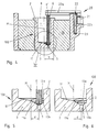
- the melting container 1 shown in FIGS. 1 to 3 is essentially divided into a wall area 2, the outer surface of which is in thermal contact with a melting device 10, which is not shown in detail in the figures, and a bottom area 3.
- a drain opening 5 of the bottom region 3 of the melting container 1 - which will be described in more detail below - can be closed by a closure element which can be moved up and down, in particular a locking rod 6 of a closure system 20, in the melting container 1 described now no longer - as in the known ones Melting containers is the case - in the area of the central axis M, but offset by a distance d from the central axis M, that is to say is arranged off-center. It is particularly advantageous here if the drain opening 5 of the base region 3 of the melting container 1 is arranged close to the wall region 2 of the melting container 1.
- the drain opening 5 of the base region 3 of the melting container 1 is arranged outwards by approximately one third of the radius R of the preferably cylindrical melting container 1, that is to say offset to the wall region 2 on the right in FIG.
- this filling cross section is increased in the radial direction by approximately one third of the radius R of the melting vessel 1.
- Larger feed containers and feed devices can advantageously be used for the melting material to be introduced into the melting container 1, so that significantly more melting material per unit time can be introduced into the interior 1 'of the melting container 1 via the filling opening 8 than with one during each filling operation known container of this type is the case.
- the melting container 100 shown in FIGS. 4 to 6 differs with regard to the arrangement of the sealing rod 6 from the melting container 1 shown in FIG. 1 in that the drain opening 5 of the base region 3 and thus the sealing rod 6 are even more similar to those on the right in FIG Wall area 2 is arranged approximately, which advantageously results in a further enlargement of the effective filling cross section of the filling opening 8 of the melting container 100.
- the person skilled in the art can easily see from the above embodiment that, in principle, the drain opening 5 can be approximated to the wall area 2 to such an extent that a correct up and down movement of the locking rod 6 of the locking system 20 is still guaranteed.
- FIGS. 1 and 4 differ in addition to the arrangement of the drain opening 5 of the floor area 3 and also in the design of the floor area 3 itself, which is shown in detail in FIGS. 2 and 3 or 5 and 6.
- the bottom region 3 is designed to fall off from all sides towards the drain opening 5, in such a way that the one shown in FIG 1 or 4 left part of the base region 3 of the melting container 1, 100 - as in the known melting containers - falls in a known manner from the left wall region 2 via a slope 11 towards the center M, but now in the case of the one in FIGS.
- the bottom area 3 widens a funnel-shaped depression 11a, in which one or two depressions 12 or 13a, 13b can be provided, so that the bottom area 3 of seen right to left is carried out at least in two stages.
- Such a design of the bottom region 3 of the melting tank 1, 100 has the advantage that the described contour of the bottom region 3 is also particularly simple, i.e. without special tools, can be formed if - as in the melting container 100 - the drain opening 5 of the bottom region 3 is arranged close to the wall region 2 of the melting container 100.
- a lifting device is used to move the locking element, in particular the locking rod 6, of the locking system 20, which essentially consists of a boom 22 which can be moved up and down by a lifting mechanism 21, the horizontal bar 22a of which engages the upper end 6 'of the locking rod 6 and its vertical Beam 22b is guided in a receiving bore 23.
Landscapes
- Engineering & Computer Science (AREA)
- Mechanical Engineering (AREA)
- Crucibles And Fluidized-Bed Furnaces (AREA)
- Feeding, Discharge, Calcimining, Fusing, And Gas-Generation Devices (AREA)
- Furnace Housings, Linings, Walls, And Ceilings (AREA)
- Vertical, Hearth, Or Arc Furnaces (AREA)
- Addition Polymer Or Copolymer, Post-Treatments, Or Chemical Modifications (AREA)
- Secondary Cells (AREA)
Abstract
Description
Die Erfindung betrifft einen Schmelzbehälter, insbesondere einen Schmelztiegel, der einen von einem Wandbereich und einem Bodenbereich begrenzten Innenraum zur Aufnahme von Schmelzgut aufweist, wobei der Bodenbereich des Schmelzbehälters eine Abflußöffnung aufweist, die durch ein Verschlußelement eines Verschlußsystems verschließbar ist.The invention relates to a melting container, in particular a melting crucible, which has an inner space delimited by a wall region and a bottom region for receiving melting material, the bottom region of the melting container having a drain opening which can be closed by a closure element of a closure system.
Ein derartiger Schmelzbehälter ist bekannt. Bei diesem ist vorgesehen, daß die Abflußöffnung des Schmelzbehälters zentriert in der Mitte des Bodens angeordnet ist. Diese Konstruktion bedingt, daß auch das diese Abflußöffnung beim Schmelzen des Schmelzgutes verschließende Verschlußelement, nämlich ein Verschlußstab, in der Zentralachse des zylindrischen Schmelztiegels liegt. Dies besitzt den Nachteil, daß durch den Verschlußstab der effektiv zur Verfügung stehende Einfüllquerschnitt der Einfüllöffnung des Schmelztiegels reduziert wird. Dieser Nachteil wird noch durch den am oberen Ende des Verschlußstabs angreifenden Hebemechanismus für eine Auf- und Abbewegung des Verschlußstabs verstärkt.Such a melting tank is known. In this it is provided that the drain opening of the melting container is arranged centered in the middle of the bottom. This construction means that the closure element, namely a closure rod, which closes this discharge opening during melting of the material to be melted, lies in the central axis of the cylindrical crucible. This has the disadvantage that the locking rod is effectively available standing filling cross section of the filling opening of the crucible is reduced. This disadvantage is exacerbated by the lifting mechanism acting on the upper end of the locking rod for an up and down movement of the locking rod.
Es ist daher Aufgabe der vorliegenden Erfindung, einen Schmelzbehälter der eingang genannten Art derart weiterzubilden, daß in besonders einfacher Art und Weise sein effektiv zur Verfügung stehender Einfüllquerschnitt vergrößert wird.It is therefore an object of the present invention to develop a melting tank of the type mentioned at the outset in such a way that its effectively available filler cross section is enlarged in a particularly simple manner.
Diese Aufgabe wird erfindungsgemäß dadurch gelöst, daß die Abflußöffnung des Bodenbereichs des Schmelzbehälters außermittig angeordnet ist.This object is achieved in that the drain opening of the bottom region of the melting tank is arranged off-center.
Durch die erfindungsgemäße Anordnung der Abflußöffnung des Bodenbereichs des erfindungsgemäßen Schmelzbehälters außermittig und insbesondere nahe an dem Wandbereich des Schmelzbehälters wird in vorteilhafter Art und Weise erreicht, daß das die Abflußöffnung verschließende Verschlußelement, insbesondere ein Verschlußstab, ebenfalls wandnah geführt werden kann, so daß der zum Einfüllen von Schmelzgut zur Verfügung stehende Einfüllquerschnitt in vorteilhafter Art und Weise deutlich vergrößert ist. Das Beschicken des Schmelztiegels mit dem Schmelzgut kann somit einfacher und vor allem schneller durchgeführt werden, da größere, das Schmelzgut aufnehmende Zuführeinrichtungen verwendet werden können. Ein weiterer Vorteil der erfindungsgemäßen Konstruktion besteht desweiteren darin, daß in vorteilhafter Art und Weise der zur Bewegung des Verschlußelements erforderliche Mechanismus des Verschlußsystems nur einen äußerst kleinen Teil der Einfüllöffnung des Schmelzbehälters versperrt.The inventive arrangement of the drain opening of the bottom region of the melting container according to the invention off-center and in particular close to the wall region of the melting container advantageously means that the closure element closing the drain opening, in particular a locking rod, can also be guided close to the wall, so that it can be filled filling cross-section available from melting material is significantly enlarged in an advantageous manner. Loading the melting crucible with the melting material can thus be carried out more easily and, above all, faster, since larger feed devices which receive the melting material can be used. Another advantage of the construction according to the invention is that the mechanism of the closure system required for moving the closure element advantageously blocks only an extremely small part of the filling opening of the melting container.
Eine vorteilhafte Weiterbildung der Erfindung sieht vor, daß der Bodenbereich in der Umgebung der Abflußöffnung des Schmelzbehälters in mindestens zwei Stufen zur Abflußöffnung hin abfällt. Eine derartige Vorgangsweise besitzt den Vorteil, daß auch bei einer asymmetrisch angeordneten Abflußöffnung im Bodenbereich des erfindungsgemäßen Schmelzbehälters eine zuverlässige und vor allem im wesentlichen vollständige Entleerung des sich darin befindlichen verflüssigten Schmelzgutes gewährleistet ist. Dies ist insbesondere beim Schmelzen von teuren Edelmetallen von großer Wichtigkeit, da hierbei aufgrund der hohen Materialkosten unbedingt darauf geachtet werden muß, daß nach dem Schmelzvorgang kein geschmolzenes Edelmetall im Schmelzbehälter zurückbleibt.An advantageous development of the invention provides that the bottom area in the vicinity of the discharge opening of the melting tank drops in at least two steps towards the discharge opening. Such a procedure has the advantage that even with an asymmetrically arranged drain opening in the bottom region of the melting tank according to the invention, it is reliable and above all essentially complete emptying of the liquefied melt contained therein is ensured. This is of great importance in particular when melting expensive precious metals, since due to the high material costs it must be ensured that no melted precious metal remains in the melting container after the melting process.
Eine weitere vorteilhafte Weiterbildung der Erfindung sieht vor, daß die mindestens Zwei zur Ausflußöffnung hin abfallende Stufen aufweisende Bodenkontur des erfindungsgemäßen Schmelzbehälters dadurch ausgebildet wird, daß in der Hälfte des Bodenbereichs des erfindungsgemäßen Schmelzbehälters, in der sich die Abflußöffnung befindet, eine entsprechende Anzahl von Senkungen im Bodenbereich vorgesehen sind. Eine derartige Ausbildung besitzt den Vorteil, daß die erfindungsgemäße Gestaltung des Bodenbereichs auch ohne Zuhilfenahme von Spezialwerkzeugen erzielt werden kann.A further advantageous development of the invention provides that the bottom contour of the melting container according to the invention, which has at least two steps descending towards the outflow opening, is formed in that in half the bottom region of the melting container according to the invention, in which the outflow opening is located, a corresponding number of depressions in the Floor area are provided. Such a design has the advantage that the design of the floor area according to the invention can also be achieved without the use of special tools.
Weitere vorteilhafte Weiterbildungen der Erfindung sind Gegenstand der Unteransprüche.Further advantageous developments of the invention are the subject of the dependent claims.
Weitere Einzelheiten der Erfindung sind den Ausführungsbeispielen zu entnehmen, die im folgenden anhand der Figuren beschrieben werden.
Es zeigen:
Figur 1- ein ersten Ausführungsbeispiel eines Schmelzbehälters,
Figur 2- eine ausschnittweise und vergrößerte Darstellung des Bereichs II der
Figur 1, Figur 3- die Darstellung der
Figur 2 ohne Verschlußelement, - Figur 4
- ein zweites Ausführungsbeispiel des Schmelzbehälters,
Figur 5- eine ausschnittsweise und vergrößerte Darstellung des Bereichs IV der Figur 4,
und Figur 6- die Darstellung der
Figur 5 ohne Verschlußelement.
Show it:
- Figure 1
- a first embodiment of a melting tank,
- Figure 2
- 2 shows a detail and enlarged representation of area II of FIG. 1,
- Figure 3
- the representation of Figure 2 without closure element,
- Figure 4
- a second embodiment of the melting tank,
- Figure 5
- 3 shows a detail and enlarged representation of area IV in FIG. 4,
and - Figure 6
- the representation of Figure 5 without closure element.
Der in Figuren 1 bis 3 dargestellte Schmelzbehälter 1 gliedert sich im wesentlichen in einen Wandbereich 2, dessen Außenfläche in thermischem Kontakt mit einer in den Figuren nicht detaillierter dargestellten Schmelzvorrichtung 10 steht, sowie einen Bodenbereich 3. In besonders vorteilhafter Art und Weise ist nun vorgesehen, daß eine Abflußöffnung 5 des Bodenbereichs 3 des Schmelzbehälters 1 - welche weiter unten noch eingehender beschrieben werden wird - durch ein auf- und abbewegbares Verschlußelement, insbesondere einen Verschlußstab 6 eines Verschlußsystems 20 verschließbar ist, beim beschriebenen Schmelzbehälter 1 nun nicht mehr - wie bei den bekannten Schmelzbehältern der Fall ist - im Bereich der Mittelachse M, sondern um einen Abstand d von der Mittelachse M versetzt, also außermittig angeordnet ist. Hierbei ist es insbesondere von Vorteil, wenn die Abflußöffnung 5 des Bodenbereichs 3 des Schmelzbehälters 1 nahe des Wandbereichs 2 des Schmelzbehälters 1 angeordnet ist.The
In dem hier gezeigten Ausführungsbeispiel der Figuren 1 bis 3 ist die Abflußöffnung 5 des Bodenbereichs 3 des Schmelzbehälters 1 etwa um ein Drittel des Radius R des vorzugsweise zylindrisch ausgeführten Schmelzbehälters 1 nach außen, also zum in Figur 1 rechten Wandbereich 2 hin versetzt angeordnet. Dies bewirkt in vorteilhafter Art und Weise, daß auch der Verschlußstab 6 des Verschlußsystems 20 seinerseits von der Mittelachse M des Schmelzbehälters 1 radial nach außen zum Wandbereich 2 hin versetzt angeordnet werden kann, so daß der zum Einfüllen eines Schmelzguts in den Innenraum 1' des Schmelzbehälters 1 zur Verfügung stehende Einfüllquerschnitt einer Einfüllöffnung 8 des Schmelzbehälters 1 nun nicht mehr - wie es bei einem bekannten derartigen Behälter der Fall sein würde - nur vom in Figur 1 linken Wandbereich 2 bis in etwa kurz vor die Mittelachse M reicht, sondern daß beim beschriebenen Schmelzbehälter 1 vielmehr in besonders vorteilhafter Art und Weise dieser Einfüllquerschnitt in radialer Richtung ca. um ein Drittel des Radiuses R des Schmelzbehälters 1 vergrößert wird. Hierdurch können in vorteilhafter Art und Weise größere Zuführbehälter und Zufüreinrichtungen für das in den Schmelzbehälter 1 einzubringende Schmelzgut verwendet werden, so daß bei jedem Füllvorgang deutlich mehr Schmelzgut pro Zeiteinheit über die Einfüllöffnung 8 in den Innenraum 1' des Schmelzbehälters 1 eingebracht werden kann als dies bei einem bekannten Behälter dieser Art der Fall ist.In the exemplary embodiment shown here in FIGS. 1 to 3, the drain opening 5 of the
Der in den Figur 4 bis 6 dargestellte Schmelzbehälter 100 unterscheidet sich im Hinblick auf die Anordnung des Verschlußstabes 6 von dem in Figur 1 dargestellten Schmelzbehälter 1 dadurch, daß die Abflußöffnung 5 des Bodenbereichs 3 und somit der Verschlußstab 6 noch weiter an den in Figur 1 rechten Wandbereich 2 angenähert angeordnet ist, woraus sich in vorteilhafter Art und Weise eine nochmalige Vergrößerung des wirksamen Einfüllquerschnitts der Einfüllöffnung 8 des Schmelzbehälters 100 ergibt. Dem Fachmann ist aus der obigen Ausführung leicht ersichtlich, daß im Prinzip die Abflußöffnung 5 soweit an den Wandbereich 2 angenähert werden kann, daß eine einwandfreie Auf- und Abbewegung des Verschlußstabes 6 des Verschlußsystems 20 noch gewährleistet ist.The
Die beiden Ausführungsbeispiele der Figuren 1 und 4 unterscheiden sich außer der Anordnung der Abflußöffnung 5 des Bodenbereichs 3 noch in der Gestaltung des Bodenbereichs 3 selbst, die in den Figuren 2 und 3 bzw. 5 und 6 detailliert dargestellt ist. Um auch bei einer asymmetrisch angeordneten Abflußöffnung 5 ein im wesentlichen vollständiges Abfließen des verflüssigten Schmelzgutes zu gewährleisten, ist in vorteilhafter Art und Weise vorgesehen, daß der Bodenbereich 3 zur Abflußöffnung 5 von allen Seiten hin abfallend ausgeführt ist, und zwar derart, daß der in Figur 1 bzw. 4 linke Teil des Bodenbereichs 3 des Schmelzbehälters 1, 100 - wie bei den bekannten Schmelzbehältern - in bekannter Art und Weise vom linken Wandbereich 2 über eine Schräge 11 hin zur Mitte M abfällt, während nun aber bei dem in Figuren 1 bzw. 4 rechten Teil des Bodenbereichs 3, also in der Umgebung der Abflußöffnung 5, vorgesehen ist, daß der Bodenbereich 3 eine trichterförmige Vertiefung 11a aufweit, in der noch eine bzw. zwei Senkungen 12 bzw. 13a, 13b vorgesehen sein können, so daß der Bodenbereich 3 von rechts nach links gesehen mindestens zweistufig ausgeführt ist.The two exemplary embodiments of FIGS. 1 and 4 differ in addition to the arrangement of the drain opening 5 of the
Eine derartige Ausbildung des Bodenbereichs 3 des Schmelzbehälters 1, 100 besitzt den Vorteil, daß die beschriebene Kontur des Bodenbereichs 3 auch dann besonders einfach, d.h. ohne Spezialwerkzeuge, ausgebildet werden kann, wenn - wie beim Schmelzbehälter 100 - die Abflußöffnung 5 des Bodenbereichs 3 nahe beim Wandbereich 2 des Schmelzbehälters 100 angeordnet ist.Such a design of the
Zur Bewegung des Verschlußelements, insbesondere des Verschlußstabs 6, des Verschlußsystems 20 dient eine Hubeinrichtung, welche im wesentlichen aus einem von einem Hubmechanismus 21 auf- und abbewegbaren Galgen 22 besteht, dessen waagrechter Balken 22a am oberen Ende 6' des Verschlußstabs 6 angreift und dessen vertikaler Balken 22b in einer Aufnahmebohrung 23 geführt ist.A lifting device is used to move the locking element, in particular the
Claims (11)
Applications Claiming Priority (2)
| Application Number | Priority Date | Filing Date | Title |
|---|---|---|---|
| DE29502809U | 1995-02-21 | ||
| DE29502809U DE29502809U1 (en) | 1995-02-21 | 1995-02-21 | Melting containers, in particular melting pots |
Publications (3)
| Publication Number | Publication Date |
|---|---|
| EP0728548A2 true EP0728548A2 (en) | 1996-08-28 |
| EP0728548A3 EP0728548A3 (en) | 1997-06-18 |
| EP0728548B1 EP0728548B1 (en) | 1999-09-15 |
Family
ID=8004196
Family Applications (1)
| Application Number | Title | Priority Date | Filing Date |
|---|---|---|---|
| EP96102233A Expired - Lifetime EP0728548B1 (en) | 1995-02-21 | 1996-02-15 | Molten metal holding vessel and meeting system using the same |
Country Status (4)
| Country | Link |
|---|---|
| EP (1) | EP0728548B1 (en) |
| AT (1) | ATE184525T1 (en) |
| DE (2) | DE29502809U1 (en) |
| ES (1) | ES2138766T3 (en) |
Cited By (1)
| Publication number | Priority date | Publication date | Assignee | Title |
|---|---|---|---|---|
| GB2351042A (en) * | 1998-05-06 | 2000-12-20 | Eastman Kodak Co | Ink jet printhead with pressure concentrater |
Families Citing this family (1)
| Publication number | Priority date | Publication date | Assignee | Title |
|---|---|---|---|---|
| DE19800853A1 (en) * | 1998-01-13 | 1999-07-15 | Ald Vacuum Techn Gmbh | Closed, evacuable crucible for inductive melting or overheating of metals, alloys or other electrically conductive materials |
Family Cites Families (2)
| Publication number | Priority date | Publication date | Assignee | Title |
|---|---|---|---|---|
| DE1246178B (en) * | 1959-10-29 | 1967-08-03 | Shinko Seiki Kabushiki Kaisha | Method and device for heating a stream of liquid metal |
| DE2934632C1 (en) * | 1979-08-28 | 1983-10-20 | Didier-Werke Ag, 6200 Wiesbaden | Bottom pouring for metallurgical vessels to hold molten steel |
-
1995
- 1995-02-21 DE DE29502809U patent/DE29502809U1/en not_active Expired - Lifetime
-
1996
- 1996-02-15 AT AT96102233T patent/ATE184525T1/en not_active IP Right Cessation
- 1996-02-15 EP EP96102233A patent/EP0728548B1/en not_active Expired - Lifetime
- 1996-02-15 DE DE59603030T patent/DE59603030D1/en not_active Expired - Lifetime
- 1996-02-15 ES ES96102233T patent/ES2138766T3/en not_active Expired - Lifetime
Cited By (2)
| Publication number | Priority date | Publication date | Assignee | Title |
|---|---|---|---|---|
| GB2351042A (en) * | 1998-05-06 | 2000-12-20 | Eastman Kodak Co | Ink jet printhead with pressure concentrater |
| GB2351042B (en) * | 1998-05-06 | 2002-02-20 | Eastman Kodak Co | An ink jet printhead unit |
Also Published As
| Publication number | Publication date |
|---|---|
| ATE184525T1 (en) | 1999-10-15 |
| DE29502809U1 (en) | 1995-04-13 |
| EP0728548B1 (en) | 1999-09-15 |
| EP0728548A3 (en) | 1997-06-18 |
| ES2138766T3 (en) | 2000-01-16 |
| DE59603030D1 (en) | 1999-10-21 |
Similar Documents
| Publication | Publication Date | Title |
|---|---|---|
| EP0385111B1 (en) | Transport and/or storage container | |
| CH642925A5 (en) | BOTTLE WITH SEPARATE DEPARTMENTS. | |
| DE3820428A1 (en) | LOCKABLE DISPENSING PACKAGING FOR LIQUID PRODUCTS | |
| DE4233227A1 (en) | DOUBLE BOTTLE NECK SEAL LID WITH HANDLING INDICATOR | |
| DE3308013A1 (en) | DOSING DEVICE | |
| EP1294508B1 (en) | Refractory pouring spout and channel unit for the arrangement on an outlet of a vessel containing molten metal, especially a tundish of a strip casting installation | |
| DE3514132A1 (en) | Container closure | |
| EP0728548A2 (en) | Molten metal holding vessel | |
| DE69005054T2 (en) | Vertical locking device for various containers. | |
| DE2620073C2 (en) | ||
| EP0287966A2 (en) | Barrel made from thermoplastic plastic | |
| DE8805975U1 (en) | Closing device for the tap hole of a tilting tap converter | |
| DE10211256A1 (en) | Dosing mechanism for dispensing e.g. harvested material from silo comprises base which closes silo and hydraulic cylinder on support frame which raises silo for controlled time away from base | |
| DE2410532C3 (en) | Dispensing and safety valve for whipped cream containers | |
| DE3700189C2 (en) | ||
| EP0342395A1 (en) | Device for introduction of powdery agents into a melting ladle | |
| EP0470097B1 (en) | Can for removing blockages | |
| DE2449516A1 (en) | SECURITY BOTTLE CAP | |
| DE3514624A1 (en) | Receptacle filling machine with a plurality of filling elements connected to a vertically adjustable upper part of the machine | |
| DE3217396A1 (en) | DOSING DEVICE WITH BALL VALVE | |
| DE9306739U1 (en) | Device for the automatic filling of liquids and pasty substances | |
| DE8708695U1 (en) | Bottle with cap | |
| AT250199B (en) | Refill-proof bottle cap | |
| EP0791419B1 (en) | Sliding gate closure for opening and closing the outlet of a casting vessel for molten metals | |
| CH401355A (en) | Container closure made of elastic material |
Legal Events
| Date | Code | Title | Description |
|---|---|---|---|
| PUAI | Public reference made under article 153(3) epc to a published international application that has entered the european phase |
Free format text: ORIGINAL CODE: 0009012 |
|
| AK | Designated contracting states |
Kind code of ref document: A2 Designated state(s): AT DE ES FR GB IT |
|
| PUAL | Search report despatched |
Free format text: ORIGINAL CODE: 0009013 |
|
| AK | Designated contracting states |
Kind code of ref document: A3 Designated state(s): AT DE ES FR GB IT |
|
| 17P | Request for examination filed |
Effective date: 19971218 |
|
| 17Q | First examination report despatched |
Effective date: 19980224 |
|
| GRAG | Despatch of communication of intention to grant |
Free format text: ORIGINAL CODE: EPIDOS AGRA |
|
| GRAG | Despatch of communication of intention to grant |
Free format text: ORIGINAL CODE: EPIDOS AGRA |
|
| GRAH | Despatch of communication of intention to grant a patent |
Free format text: ORIGINAL CODE: EPIDOS IGRA |
|
| GRAH | Despatch of communication of intention to grant a patent |
Free format text: ORIGINAL CODE: EPIDOS IGRA |
|
| GRAA | (expected) grant |
Free format text: ORIGINAL CODE: 0009210 |
|
| AK | Designated contracting states |
Kind code of ref document: B1 Designated state(s): AT DE ES FR GB IT |
|
| REF | Corresponds to: |
Ref document number: 184525 Country of ref document: AT Date of ref document: 19991015 Kind code of ref document: T |
|
| REF | Corresponds to: |
Ref document number: 59603030 Country of ref document: DE Date of ref document: 19991021 |
|
| ET | Fr: translation filed | ||
| ITF | It: translation for a ep patent filed | ||
| GBT | Gb: translation of ep patent filed (gb section 77(6)(a)/1977) |
Effective date: 19991216 |
|
| REG | Reference to a national code |
Ref country code: ES Ref legal event code: FG2A Ref document number: 2138766 Country of ref document: ES Kind code of ref document: T3 |
|
| PLBE | No opposition filed within time limit |
Free format text: ORIGINAL CODE: 0009261 |
|
| STAA | Information on the status of an ep patent application or granted ep patent |
Free format text: STATUS: NO OPPOSITION FILED WITHIN TIME LIMIT |
|
| 26N | No opposition filed | ||
| PGFP | Annual fee paid to national office [announced via postgrant information from national office to epo] |
Ref country code: GB Payment date: 20010207 Year of fee payment: 6 |
|
| PGFP | Annual fee paid to national office [announced via postgrant information from national office to epo] |
Ref country code: FR Payment date: 20010215 Year of fee payment: 6 |
|
| PGFP | Annual fee paid to national office [announced via postgrant information from national office to epo] |
Ref country code: ES Payment date: 20010221 Year of fee payment: 6 Ref country code: AT Payment date: 20010221 Year of fee payment: 6 |
|
| REG | Reference to a national code |
Ref country code: GB Ref legal event code: IF02 |
|
| PG25 | Lapsed in a contracting state [announced via postgrant information from national office to epo] |
Ref country code: GB Free format text: LAPSE BECAUSE OF NON-PAYMENT OF DUE FEES Effective date: 20020215 Ref country code: AT Free format text: LAPSE BECAUSE OF NON-PAYMENT OF DUE FEES Effective date: 20020215 |
|
| PG25 | Lapsed in a contracting state [announced via postgrant information from national office to epo] |
Ref country code: ES Free format text: LAPSE BECAUSE OF NON-PAYMENT OF DUE FEES Effective date: 20020216 |
|
| GBPC | Gb: european patent ceased through non-payment of renewal fee |
Effective date: 20020215 |
|
| PG25 | Lapsed in a contracting state [announced via postgrant information from national office to epo] |
Ref country code: FR Free format text: LAPSE BECAUSE OF NON-PAYMENT OF DUE FEES Effective date: 20021031 |
|
| REG | Reference to a national code |
Ref country code: FR Ref legal event code: ST |
|
| PG25 | Lapsed in a contracting state [announced via postgrant information from national office to epo] |
Ref country code: IT Free format text: LAPSE BECAUSE OF NON-PAYMENT OF DUE FEES;WARNING: LAPSES OF ITALIAN PATENTS WITH EFFECTIVE DATE BEFORE 2007 MAY HAVE OCCURRED AT ANY TIME BEFORE 2007. THE CORRECT EFFECTIVE DATE MAY BE DIFFERENT FROM THE ONE RECORDED. Effective date: 20050215 |
|
| REG | Reference to a national code |
Ref country code: DE Ref legal event code: R082 Ref document number: 59603030 Country of ref document: DE Representative=s name: HOEGER, STELLRECHT & PARTNER PATENTANWAELTE MB, DE |
|
| PGFP | Annual fee paid to national office [announced via postgrant information from national office to epo] |
Ref country code: DE Payment date: 20150327 Year of fee payment: 20 |
|
| REG | Reference to a national code |
Ref country code: DE Ref legal event code: R071 Ref document number: 59603030 Country of ref document: DE |