EP0728548A2 - Récipient pour métal liquide - Google Patents
Récipient pour métal liquide Download PDFInfo
- Publication number
- EP0728548A2 EP0728548A2 EP96102233A EP96102233A EP0728548A2 EP 0728548 A2 EP0728548 A2 EP 0728548A2 EP 96102233 A EP96102233 A EP 96102233A EP 96102233 A EP96102233 A EP 96102233A EP 0728548 A2 EP0728548 A2 EP 0728548A2
- Authority
- EP
- European Patent Office
- Prior art keywords
- melting
- melting container
- container
- opening
- drain opening
- Prior art date
- Legal status (The legal status is an assumption and is not a legal conclusion. Google has not performed a legal analysis and makes no representation as to the accuracy of the status listed.)
- Granted
Links
Images

Classifications
-
- B—PERFORMING OPERATIONS; TRANSPORTING
- B22—CASTING; POWDER METALLURGY
- B22D—CASTING OF METALS; CASTING OF OTHER SUBSTANCES BY THE SAME PROCESSES OR DEVICES
- B22D41/00—Casting melt-holding vessels, e.g. ladles, tundishes, cups or the like
- B22D41/14—Closures
- B22D41/16—Closures stopper-rod type, i.e. a stopper-rod being positioned downwardly through the vessel and the metal therein, for selective registry with the pouring opening
- B22D41/20—Stopper-rod operating equipment
-
- B—PERFORMING OPERATIONS; TRANSPORTING
- B22—CASTING; POWDER METALLURGY
- B22D—CASTING OF METALS; CASTING OF OTHER SUBSTANCES BY THE SAME PROCESSES OR DEVICES
- B22D41/00—Casting melt-holding vessels, e.g. ladles, tundishes, cups or the like
- B22D41/50—Pouring-nozzles
Definitions
- the invention relates to a melting container, in particular a melting crucible, which has an inner space delimited by a wall region and a bottom region for receiving melting material, the bottom region of the melting container having a drain opening which can be closed by a closure element of a closure system.
- Such a melting tank is known.
- the drain opening of the melting container is arranged centered in the middle of the bottom.
- the closure element namely a closure rod, which closes this discharge opening during melting of the material to be melted, lies in the central axis of the cylindrical crucible.
- This object is achieved in that the drain opening of the bottom region of the melting tank is arranged off-center.
- the inventive arrangement of the drain opening of the bottom region of the melting container according to the invention off-center and in particular close to the wall region of the melting container advantageously means that the closure element closing the drain opening, in particular a locking rod, can also be guided close to the wall, so that it can be filled filling cross-section available from melting material is significantly enlarged in an advantageous manner. Loading the melting crucible with the melting material can thus be carried out more easily and, above all, faster, since larger feed devices which receive the melting material can be used.
- Another advantage of the construction according to the invention is that the mechanism of the closure system required for moving the closure element advantageously blocks only an extremely small part of the filling opening of the melting container.
- An advantageous development of the invention provides that the bottom area in the vicinity of the discharge opening of the melting tank drops in at least two steps towards the discharge opening.
- Such a procedure has the advantage that even with an asymmetrically arranged drain opening in the bottom region of the melting tank according to the invention, it is reliable and above all essentially complete emptying of the liquefied melt contained therein is ensured. This is of great importance in particular when melting expensive precious metals, since due to the high material costs it must be ensured that no melted precious metal remains in the melting container after the melting process.
- a further advantageous development of the invention provides that the bottom contour of the melting container according to the invention, which has at least two steps descending towards the outflow opening, is formed in that in half the bottom region of the melting container according to the invention, in which the outflow opening is located, a corresponding number of depressions in the Floor area are provided.
- Such a design has the advantage that the design of the floor area according to the invention can also be achieved without the use of special tools.
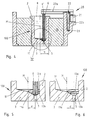
- the melting container 1 shown in FIGS. 1 to 3 is essentially divided into a wall area 2, the outer surface of which is in thermal contact with a melting device 10, which is not shown in detail in the figures, and a bottom area 3.
- a drain opening 5 of the bottom region 3 of the melting container 1 - which will be described in more detail below - can be closed by a closure element which can be moved up and down, in particular a locking rod 6 of a closure system 20, in the melting container 1 described now no longer - as in the known ones Melting containers is the case - in the area of the central axis M, but offset by a distance d from the central axis M, that is to say is arranged off-center. It is particularly advantageous here if the drain opening 5 of the base region 3 of the melting container 1 is arranged close to the wall region 2 of the melting container 1.
- the drain opening 5 of the base region 3 of the melting container 1 is arranged outwards by approximately one third of the radius R of the preferably cylindrical melting container 1, that is to say offset to the wall region 2 on the right in FIG.
- this filling cross section is increased in the radial direction by approximately one third of the radius R of the melting vessel 1.
- Larger feed containers and feed devices can advantageously be used for the melting material to be introduced into the melting container 1, so that significantly more melting material per unit time can be introduced into the interior 1 'of the melting container 1 via the filling opening 8 than with one during each filling operation known container of this type is the case.
- the melting container 100 shown in FIGS. 4 to 6 differs with regard to the arrangement of the sealing rod 6 from the melting container 1 shown in FIG. 1 in that the drain opening 5 of the base region 3 and thus the sealing rod 6 are even more similar to those on the right in FIG Wall area 2 is arranged approximately, which advantageously results in a further enlargement of the effective filling cross section of the filling opening 8 of the melting container 100.
- the person skilled in the art can easily see from the above embodiment that, in principle, the drain opening 5 can be approximated to the wall area 2 to such an extent that a correct up and down movement of the locking rod 6 of the locking system 20 is still guaranteed.
- FIGS. 1 and 4 differ in addition to the arrangement of the drain opening 5 of the floor area 3 and also in the design of the floor area 3 itself, which is shown in detail in FIGS. 2 and 3 or 5 and 6.
- the bottom region 3 is designed to fall off from all sides towards the drain opening 5, in such a way that the one shown in FIG 1 or 4 left part of the base region 3 of the melting container 1, 100 - as in the known melting containers - falls in a known manner from the left wall region 2 via a slope 11 towards the center M, but now in the case of the one in FIGS.
- the bottom area 3 widens a funnel-shaped depression 11a, in which one or two depressions 12 or 13a, 13b can be provided, so that the bottom area 3 of seen right to left is carried out at least in two stages.
- Such a design of the bottom region 3 of the melting tank 1, 100 has the advantage that the described contour of the bottom region 3 is also particularly simple, i.e. without special tools, can be formed if - as in the melting container 100 - the drain opening 5 of the bottom region 3 is arranged close to the wall region 2 of the melting container 100.
- a lifting device is used to move the locking element, in particular the locking rod 6, of the locking system 20, which essentially consists of a boom 22 which can be moved up and down by a lifting mechanism 21, the horizontal bar 22a of which engages the upper end 6 'of the locking rod 6 and its vertical Beam 22b is guided in a receiving bore 23.
Landscapes
- Engineering & Computer Science (AREA)
- Mechanical Engineering (AREA)
- Crucibles And Fluidized-Bed Furnaces (AREA)
- Feeding, Discharge, Calcimining, Fusing, And Gas-Generation Devices (AREA)
- Vertical, Hearth, Or Arc Furnaces (AREA)
- Addition Polymer Or Copolymer, Post-Treatments, Or Chemical Modifications (AREA)
- Furnace Housings, Linings, Walls, And Ceilings (AREA)
- Secondary Cells (AREA)
Applications Claiming Priority (2)
| Application Number | Priority Date | Filing Date | Title |
|---|---|---|---|
| DE29502809U DE29502809U1 (de) | 1995-02-21 | 1995-02-21 | Schmelzbehälter, insbesondere Schmelztiegel |
| DE29502809U | 1995-02-21 |
Publications (3)
| Publication Number | Publication Date |
|---|---|
| EP0728548A2 true EP0728548A2 (fr) | 1996-08-28 |
| EP0728548A3 EP0728548A3 (fr) | 1997-06-18 |
| EP0728548B1 EP0728548B1 (fr) | 1999-09-15 |
Family
ID=8004196
Family Applications (1)
| Application Number | Title | Priority Date | Filing Date |
|---|---|---|---|
| EP96102233A Expired - Lifetime EP0728548B1 (fr) | 1995-02-21 | 1996-02-15 | Récipient pour métal liquide et appareille de fusion utilisant ce récipient |
Country Status (4)
| Country | Link |
|---|---|
| EP (1) | EP0728548B1 (fr) |
| AT (1) | ATE184525T1 (fr) |
| DE (2) | DE29502809U1 (fr) |
| ES (1) | ES2138766T3 (fr) |
Cited By (1)
| Publication number | Priority date | Publication date | Assignee | Title |
|---|---|---|---|---|
| GB2351042A (en) * | 1998-05-06 | 2000-12-20 | Eastman Kodak Co | Ink jet printhead with pressure concentrater |
Families Citing this family (1)
| Publication number | Priority date | Publication date | Assignee | Title |
|---|---|---|---|---|
| DE19800853A1 (de) * | 1998-01-13 | 1999-07-15 | Ald Vacuum Techn Gmbh | Geschlossener, evakuierbarer Tiegel zum induktiven Schmelzen oder Überhitzen von Metallen, Legierungen oder anderen elektrisch leitfähigen Werkstoffen |
Family Cites Families (2)
| Publication number | Priority date | Publication date | Assignee | Title |
|---|---|---|---|---|
| DE1246178B (de) * | 1959-10-29 | 1967-08-03 | Shinko Seiki Kabushiki Kaisha | Verfahren und Vorrichtung zum Aufheizen eines Stromes fluessigen Metalls |
| DE2934632C1 (de) * | 1979-08-28 | 1983-10-20 | Didier-Werke Ag, 6200 Wiesbaden | Bodenausguss fuer metallurgische Gefaesse zur Aufnahme von Stahlschmelze |
-
1995
- 1995-02-21 DE DE29502809U patent/DE29502809U1/de not_active Expired - Lifetime
-
1996
- 1996-02-15 EP EP96102233A patent/EP0728548B1/fr not_active Expired - Lifetime
- 1996-02-15 DE DE59603030T patent/DE59603030D1/de not_active Expired - Lifetime
- 1996-02-15 ES ES96102233T patent/ES2138766T3/es not_active Expired - Lifetime
- 1996-02-15 AT AT96102233T patent/ATE184525T1/de not_active IP Right Cessation
Cited By (2)
| Publication number | Priority date | Publication date | Assignee | Title |
|---|---|---|---|---|
| GB2351042A (en) * | 1998-05-06 | 2000-12-20 | Eastman Kodak Co | Ink jet printhead with pressure concentrater |
| GB2351042B (en) * | 1998-05-06 | 2002-02-20 | Eastman Kodak Co | An ink jet printhead unit |
Also Published As
| Publication number | Publication date |
|---|---|
| DE29502809U1 (de) | 1995-04-13 |
| EP0728548A3 (fr) | 1997-06-18 |
| ES2138766T3 (es) | 2000-01-16 |
| DE59603030D1 (de) | 1999-10-21 |
| EP0728548B1 (fr) | 1999-09-15 |
| ATE184525T1 (de) | 1999-10-15 |
Similar Documents
| Publication | Publication Date | Title |
|---|---|---|
| EP0385111B1 (fr) | Récipient de transport et/ou de stockage | |
| CH642925A5 (de) | Flasche mit getrennten abteilungen. | |
| DE3820428A1 (de) | Verschliessbare dispensierverpackung fuer fluessige produkte | |
| DE4233227A1 (de) | Doppelflaschenhals-siegeldeckel mit handhabungsanzeige | |
| DE3308013A1 (de) | Dosiervorrichtung | |
| EP1294508B1 (fr) | Unite de busette de coulee refractaire a monter sur la goulotte d'une cuve contenant une matiere en fusion, notamment le panier de coulee d'une installation de coulee en bande | |
| DE3514132A1 (de) | Behaelterverschluss | |
| EP0728548A2 (fr) | Récipient pour métal liquide | |
| DE69005054T2 (de) | Senkrecht bewegliche Verschlussvorrichtung für verschiedene Behälter. | |
| DE2620073C2 (fr) | ||
| EP0287966A2 (fr) | Baril en matière thermoplastique | |
| DE8805975U1 (de) | Verschlußvorrichtung für das Abstichloch eines kippbaren Abstichkonverters | |
| DE10211256A1 (de) | Vorrichtung zur dosierten Abgabe von Schüttgut | |
| DE2410532C3 (de) | Abgabe- und Sicherheitsventil für Schlagsahnebehälter | |
| DE3700189C2 (fr) | ||
| EP0342395A1 (fr) | Dispositif pour introduire des réactifs pulvérulents dans une poche de fusion | |
| EP0470097B1 (fr) | Boite de debouchage | |
| DE2449516A1 (de) | Sicherheits-flaschenverschluss | |
| DE3514624A1 (de) | Gefaessfuellmaschine mit mehreren an einem hoehenverstellbaren maschinenoberteil angeschlossenen fuellelementen | |
| DE3217396A1 (de) | Dosiervorrichtung mit kugelventil | |
| DE9306739U1 (de) | Vorrichtung zum automatischen Einfüllen von Flüssigkeiten und pastösen Stoffen | |
| DE8708695U1 (de) | Flasche mit Kappe | |
| AT250199B (de) | Nachfüllsicherer Flaschenverschluß | |
| DE2300951A1 (de) | Verfahren und vorrichtung zum abfuellen einer fluessigkeit in einen behaelter ohne lufteinschluesse | |
| EP0791419B1 (fr) | Dispositif de fermeture coulissante pour ouvrir et fermer le canal d'évacuation d'un récipient de coulée contenant des métaux fondus |
Legal Events
| Date | Code | Title | Description |
|---|---|---|---|
| PUAI | Public reference made under article 153(3) epc to a published international application that has entered the european phase |
Free format text: ORIGINAL CODE: 0009012 |
|
| AK | Designated contracting states |
Kind code of ref document: A2 Designated state(s): AT DE ES FR GB IT |
|
| PUAL | Search report despatched |
Free format text: ORIGINAL CODE: 0009013 |
|
| AK | Designated contracting states |
Kind code of ref document: A3 Designated state(s): AT DE ES FR GB IT |
|
| 17P | Request for examination filed |
Effective date: 19971218 |
|
| 17Q | First examination report despatched |
Effective date: 19980224 |
|
| GRAG | Despatch of communication of intention to grant |
Free format text: ORIGINAL CODE: EPIDOS AGRA |
|
| GRAG | Despatch of communication of intention to grant |
Free format text: ORIGINAL CODE: EPIDOS AGRA |
|
| GRAH | Despatch of communication of intention to grant a patent |
Free format text: ORIGINAL CODE: EPIDOS IGRA |
|
| GRAH | Despatch of communication of intention to grant a patent |
Free format text: ORIGINAL CODE: EPIDOS IGRA |
|
| GRAA | (expected) grant |
Free format text: ORIGINAL CODE: 0009210 |
|
| AK | Designated contracting states |
Kind code of ref document: B1 Designated state(s): AT DE ES FR GB IT |
|
| REF | Corresponds to: |
Ref document number: 184525 Country of ref document: AT Date of ref document: 19991015 Kind code of ref document: T |
|
| REF | Corresponds to: |
Ref document number: 59603030 Country of ref document: DE Date of ref document: 19991021 |
|
| ET | Fr: translation filed | ||
| ITF | It: translation for a ep patent filed | ||
| GBT | Gb: translation of ep patent filed (gb section 77(6)(a)/1977) |
Effective date: 19991216 |
|
| REG | Reference to a national code |
Ref country code: ES Ref legal event code: FG2A Ref document number: 2138766 Country of ref document: ES Kind code of ref document: T3 |
|
| PLBE | No opposition filed within time limit |
Free format text: ORIGINAL CODE: 0009261 |
|
| STAA | Information on the status of an ep patent application or granted ep patent |
Free format text: STATUS: NO OPPOSITION FILED WITHIN TIME LIMIT |
|
| 26N | No opposition filed | ||
| PGFP | Annual fee paid to national office [announced via postgrant information from national office to epo] |
Ref country code: GB Payment date: 20010207 Year of fee payment: 6 |
|
| PGFP | Annual fee paid to national office [announced via postgrant information from national office to epo] |
Ref country code: FR Payment date: 20010215 Year of fee payment: 6 |
|
| PGFP | Annual fee paid to national office [announced via postgrant information from national office to epo] |
Ref country code: ES Payment date: 20010221 Year of fee payment: 6 Ref country code: AT Payment date: 20010221 Year of fee payment: 6 |
|
| REG | Reference to a national code |
Ref country code: GB Ref legal event code: IF02 |
|
| PG25 | Lapsed in a contracting state [announced via postgrant information from national office to epo] |
Ref country code: GB Free format text: LAPSE BECAUSE OF NON-PAYMENT OF DUE FEES Effective date: 20020215 Ref country code: AT Free format text: LAPSE BECAUSE OF NON-PAYMENT OF DUE FEES Effective date: 20020215 |
|
| PG25 | Lapsed in a contracting state [announced via postgrant information from national office to epo] |
Ref country code: ES Free format text: LAPSE BECAUSE OF NON-PAYMENT OF DUE FEES Effective date: 20020216 |
|
| GBPC | Gb: european patent ceased through non-payment of renewal fee |
Effective date: 20020215 |
|
| PG25 | Lapsed in a contracting state [announced via postgrant information from national office to epo] |
Ref country code: FR Free format text: LAPSE BECAUSE OF NON-PAYMENT OF DUE FEES Effective date: 20021031 |
|
| REG | Reference to a national code |
Ref country code: FR Ref legal event code: ST |
|
| PG25 | Lapsed in a contracting state [announced via postgrant information from national office to epo] |
Ref country code: IT Free format text: LAPSE BECAUSE OF NON-PAYMENT OF DUE FEES;WARNING: LAPSES OF ITALIAN PATENTS WITH EFFECTIVE DATE BEFORE 2007 MAY HAVE OCCURRED AT ANY TIME BEFORE 2007. THE CORRECT EFFECTIVE DATE MAY BE DIFFERENT FROM THE ONE RECORDED. Effective date: 20050215 |
|
| REG | Reference to a national code |
Ref country code: DE Ref legal event code: R082 Ref document number: 59603030 Country of ref document: DE Representative=s name: HOEGER, STELLRECHT & PARTNER PATENTANWAELTE MB, DE |
|
| PGFP | Annual fee paid to national office [announced via postgrant information from national office to epo] |
Ref country code: DE Payment date: 20150327 Year of fee payment: 20 |
|
| REG | Reference to a national code |
Ref country code: DE Ref legal event code: R071 Ref document number: 59603030 Country of ref document: DE |