EP0728582A2 - Dispositif pour nettoyer des cylindres de machines à imprimer - Google Patents
Dispositif pour nettoyer des cylindres de machines à imprimer Download PDFInfo
- Publication number
- EP0728582A2 EP0728582A2 EP96101642A EP96101642A EP0728582A2 EP 0728582 A2 EP0728582 A2 EP 0728582A2 EP 96101642 A EP96101642 A EP 96101642A EP 96101642 A EP96101642 A EP 96101642A EP 0728582 A2 EP0728582 A2 EP 0728582A2
- Authority
- EP
- European Patent Office
- Prior art keywords
- cylinder
- cleaning device
- cleaning
- centering
- cylinders
- Prior art date
- Legal status (The legal status is an assumption and is not a legal conclusion. Google has not performed a legal analysis and makes no representation as to the accuracy of the status listed.)
- Granted
Links
Images
Classifications
-
- B—PERFORMING OPERATIONS; TRANSPORTING
- B41—PRINTING; LINING MACHINES; TYPEWRITERS; STAMPS
- B41F—PRINTING MACHINES OR PRESSES
- B41F35/00—Cleaning arrangements or devices
- B41F35/006—Cleaning arrangements or devices for impression cylinders
Definitions
- the invention relates to a device for cleaning cylinders in printing presses with a cleaning device which can be turned on and off the cylinder.
- a device of this type is known from DE 36 14 542 A1.
- This cleaning device is used to clean a plurality of cylinders within a rotary printing press, in that it can be moved in succession to a plurality of cylinders in different printing presses by means of a transport device.
- the transport device can be moved along the printing press by means of conveying means in a guide system.
- the conveying means are in engagement with a drive unit. It is disadvantageous here that the necessary means are very complex and the time required for moving the cleaning device from one printing unit to the next printing unit is high.
- Another printing press cylinder washing device is known from EP 0 591 634 A1.
- This device can be extended and retracted axially parallel to a cylinder in an opening in a machine frame.
- the washing device itself is accommodated in a suspension device having linear guides.
- the suspension device has end connections for coupling or decoupling supply lines in such a way that a connection is automatically generated when the washing device is inserted.
- the suspension device with washing device is pivoted onto or off the cylinder to be cleaned by means of a compressed air cylinder and coupling gear.
- the compressed air cylinders and the suspension device are arranged in the opening and thus considerably restrict the space for service work.
- the linear guides and the coupling gear represent a complex solution.
- the object of the invention is to provide a device for cleaning cylinders, which can be installed and removed in a printing press with little effort, without constantly restricting the space for service work.
- the positioned cleaning device can be pushed in laterally on an industrial conveyor to a cylinder to be cleaned through the opening of a printing press and can be moved out on the industrial conveyor.
- the flow conveyor can be moved so that only one floor conveyor is required for all cleaning devices within a printing press.
- Transverse guides are preferably arranged in an opening on the machine frame (running parallel to the axis of the cylinder), into which the industrial truck with cleaning device can be pushed into and out of an "insertion position". From the "insertion position", the cleaning device leaving the industrial truck is moved longitudinally by means of a first actuating device via longitudinal guides into a "standby position" to the cylinder to be cleaned, i.e. in the direction of sheet travel or against the sheet travel direction. By means of a second actuating device, the cleaning device is then put into the “working position” or put back into the “ready position”.
- the solution according to the invention is particularly suitable for cleaning cylinders, for example impression cylinders in printing machines. These impression cylinders are difficult to access due to their geometrical arrangement within the printing press. If the solution according to the invention is used in a sheet-fed printing press of a higher format class, the cleaning device has a relatively high mass. Such a device can be installed or removed manually only with great effort.
- washing rollers for example washing brushes with a squeegee or a washing machine with a pressure element
- Washing rollers or the washing cloth spindles are mounted in the side walls arranged on the end face and are surrounded by a housing, which is preferably open on one side.
- nozzles for detergent and / or water in the housing are assigned to the washing rollers or the wash cloth.
- a roller drive for. B. an electric motor, arranged on the housing so that a complete cleaning unit is available as an assembly (including the connections for water, detergent and energy).
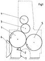
- a printing unit of a sheet-fed offset printing press essentially consists of a printing cylinder 1 which acts as an impression cylinder and which is operatively connected in a known manner to an adjacent blanket cylinder 3 and a plate cylinder 4 assigned to the blanket cylinder 3.
- a transfer drum 5 is arranged upstream of the printing cylinder 1 in the direction of sheet travel and a further transfer drum 6 is arranged downstream.
- a cleaning device 2 is to be arranged, which can be placed on and off the printing cylinder 1.
- the printing unit each has a laterally arranged machine frame 7, in which there is an opening.
- This opening serves in a known manner as a "man hole” for service work.
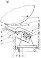
- Cross guides 9 running parallel to the cylinder 1 are arranged on the machine frame 7 within the opening.
- a floor conveyor 8 essentially formed from a base frame with brackets accommodates the cleaning device 2.
- the industrial conveyor 8 has a plurality of steering rollers 18 which are used for moving between the printing units.
- 9 centering rollers 17 are rotatably arranged on the industrial conveyor 8 parallel to the transverse guides.
- the industrial conveyor 8 can also be movable on an air cushion or by means of guide devices arranged, for example, in the floor area.
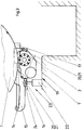
- An actuating device 12 is arranged on the side of each machine frame 7 below the cylinder 1. It consists essentially of a working cylinder 13 with a piston rod, which is received in a pivot joint 14. A lever 15 is also accommodated in the swivel joint 14 and has a cam roller 16 which is in contact with a longitudinal guide 11 fixed to the frame. Each lever 15 has centerings 20, to which centering means 21 arranged on the cleaning device 2 are assigned in the correct position.
- the cleaning device 2 furthermore has connections for detergent, water and energy, which are automatically coupled with corresponding counterparts at the latest in the “ready position” assigned to the cylinder 1 to be cleaned. The cleaning device is thus connected to all the supply lines required.
- the mode of operation is as follows: the cleaning device 2 is positioned on the industrial conveyor 8.
- the industrial conveyor 8 provided with steering rollers 18 is moved from one side into an opening in the machine frame 7 of the printing press into a "insertion position 10".
- the centering rollers 17 which are arranged on the industrial conveyor 8 and which engage with the transverse guides 9 fixed to the frame serve for this purpose.
- the transverse guides 9 are preferably provided on the open side with a bevel so that the industrial conveyor 8 can be accommodated in the transverse guides 9 with little effort on the end face.
- the housing of the cleaning device 2 is brought closer to the levers 15 of the first actuating device 12.
- the levers 15 have centerings which form-fit with the centering means 21 on the housing of the cleaning device 2. If a coupling has taken place between the centerings 20 and the centering means 21, the insertion position 10 has been reached.
- the first actuating device 12 now moves the cleaning device 2 along the longitudinal guides 11 by means of the lever 15 and the working cylinder 13.
- Each cam roller 16 runs on the longitudinal guide 11.
- the law of motion of the longitudinal guide 11 and lever 15 with cam roller 16 is designed such that the cleaning device 2 from the insertion position 10 (and thus also) out of the industrial conveyor 8 during the longitudinal displacement is lifted out. This clears the floor conveyor 8.
- the industrial conveyor 8 can, for example, be removed from the printing press, accommodate a further cleaning device 2 and thus feed a further printing unit.
- the actuating device 12 is activated until the cleaning device 2 has reached a standby position 19. That is, the working cylinders 13 move to a predetermined position (standby position 19) and move the levers 15 with the cleaning device 2 via the longitudinal guides 11.
- the cleaning device 2 is held in the standby position 19 by the actuating device 12. In this position 19, the cleaning device 2 is automatically connected to the connections for water, detergent and energy. If the cleaning device 2 is to clean the printing cylinder, the second actuating device 23 is activated. The working cylinder 22 lifts the cleaning device 2 via the cross member 24 around the swivel joint 14 until the cleaning device 2 rests on the pressure cylinder 1. So that the job is done, the pressure cylinder 1 can be washed in a known manner. If the cleaning device 2 is to be switched off, the rod of the working cylinder 22 is retracted and the cleaning device 2 is thus lowered into the standby position 19.
- the cleaning device 2 If the cleaning device 2 is to be replaced, for example for service purposes, it is moved back from the standby position 19 into the insertion position 10 via the longitudinal guides 11 and placed on a provided floor conveyor 8.
- the industrial truck 8 can then be laterally moved out of the opening in the machine frame 7 again.
- the same cleaning device can also be moved to another printing unit by means of industrial conveyors 8.
- the first actuating device 12 shown can alternatively also be formed by a drive motor which moves the cleaning device 2 from the insertion position 10 into the ready position 19 by means of longitudinal guides 11 by means of a cable pull.
Landscapes
- Inking, Control Or Cleaning Of Printing Machines (AREA)
- Manufacturing Of Printed Wiring (AREA)
Applications Claiming Priority (2)
| Application Number | Priority Date | Filing Date | Title |
|---|---|---|---|
| DE19506640 | 1995-02-25 | ||
| DE19506640A DE19506640C2 (de) | 1995-02-25 | 1995-02-25 | Einrichtung zum Reinigen von Zylindern in Druckmaschinen |
Publications (3)
| Publication Number | Publication Date |
|---|---|
| EP0728582A2 true EP0728582A2 (fr) | 1996-08-28 |
| EP0728582A3 EP0728582A3 (fr) | 1996-11-20 |
| EP0728582B1 EP0728582B1 (fr) | 1998-05-20 |
Family
ID=7755043
Family Applications (1)
| Application Number | Title | Priority Date | Filing Date |
|---|---|---|---|
| EP96101642A Expired - Lifetime EP0728582B1 (fr) | 1995-02-25 | 1996-02-06 | Dispositif pour nettoyer des cylindres de machines à imprimer |
Country Status (5)
| Country | Link |
|---|---|
| US (1) | US5615612A (fr) |
| EP (1) | EP0728582B1 (fr) |
| JP (1) | JP2889172B2 (fr) |
| AT (1) | ATE166289T1 (fr) |
| DE (2) | DE19506640C2 (fr) |
Families Citing this family (10)
| Publication number | Priority date | Publication date | Assignee | Title |
|---|---|---|---|---|
| DE19753231A1 (de) * | 1997-12-01 | 1999-06-02 | Heidelberger Druckmasch Ag | Vorrichtung zur Reinigung eines Zylinders in einer Druckmaschine |
| DE19807505A1 (de) * | 1998-02-21 | 1999-08-26 | Roland Man Druckmasch | Bogenrotationsdruckmaschine mit Druckeinheiten für den Mehrfarbendruck und wenigstens einer Beschichtungseinheit |
| US6951172B2 (en) * | 1998-03-31 | 2005-10-04 | Heidelberger Druckmaschinen Ag | Accessory for a printing unit |
| DE19941943B4 (de) | 1998-10-08 | 2008-11-13 | Heidelberger Druckmaschinen Ag | Verfahren und Vorrichtung zur Entnahme einer Reinigungseinrichtung aus einer Druckmaschine |
| DE19958087B4 (de) | 1998-12-24 | 2008-07-03 | Heidelberger Druckmaschinen Ag | Verfahren zur Entnahme und zum Einsetzen einer Reinigungseinrichtung sowie Druckmaschine |
| DE10040950B4 (de) | 1999-09-15 | 2009-04-02 | Heidelberger Druckmaschinen Ag | Druckmaschine |
| DE10000558A1 (de) * | 2000-01-08 | 2001-07-12 | Baldwin Grafotec Gmbh | Wascheinrichtung für Druckmaschinenzylinder |
| DE10000554A1 (de) * | 2000-01-08 | 2001-07-12 | Baldwin Grafotec Gmbh | Waschanlage für Druckmaschinenzylinder |
| CN1853930A (zh) | 2005-04-20 | 2006-11-01 | 海德堡印刷机械股份公司 | 用于运行印刷机的方法 |
| US20080289364A1 (en) * | 2007-05-23 | 2008-11-27 | Pinkham Jr Daniel | Method and system for preheating glass batch or ingredient(s) |
Family Cites Families (13)
| Publication number | Priority date | Publication date | Assignee | Title |
|---|---|---|---|---|
| US3783782A (en) * | 1972-08-04 | 1974-01-08 | Faustel Inc | Revolving turret for supporting printing press cart |
| US3845713A (en) * | 1973-01-29 | 1974-11-05 | Pitney Bowes Inc | Automatic etcher for offset master |
| JPS5730120Y2 (fr) * | 1980-01-08 | 1982-07-01 | ||
| DD227927A1 (de) * | 1984-11-02 | 1985-10-02 | Polygraph Leipzig | Vorrichtung zur reinigung eines zylinders einer druckmaschine |
| DE3614542A1 (de) * | 1986-04-29 | 1987-11-05 | Roland Man Druckmasch | Einrichtung zum waschen von zylindern in rotationsdruckmaschinen |
| DE3744800A1 (de) * | 1987-10-28 | 1989-06-29 | Spiess Gmbh G | Gummituchwaschvorrichtung |
| EP0364901B1 (fr) * | 1988-10-19 | 1994-04-27 | Dai Nippon Insatsu Kabushiki Kaisha | Système de nettoyage pour presses d'impression offset à feuilles |
| DE3909119C2 (de) * | 1989-03-20 | 1997-01-23 | Heidelberger Druckmasch Ag | Wascheinrichtung für eine Druckmaschine |
| US5060569A (en) * | 1989-06-22 | 1991-10-29 | Didde Web Press Corporation | Apparatus for changeover of cylinders in web fed printing press |
| DE9014229U1 (de) * | 1990-10-13 | 1990-12-20 | Vliesstoff Kasper GmbH, 4050 Mönchengladbach | Umwickelvorrichtung zum Umwickeln einer Großrolle auf eine Saubertuchspindel |
| DE4215355C2 (de) * | 1992-05-13 | 1995-09-21 | Roland Man Druckmasch | Waschvorrichtung für Zylinder in Druckmaschinen, insbesondere Bogenoffsetdruckmaschinen |
| DE4233953A1 (de) * | 1992-10-08 | 1994-04-14 | Baldwin Gegenheimer Gmbh | Druckmaschinenzylinder-Waschvorrichtung |
| DK172546B1 (da) * | 1993-02-03 | 1998-12-21 | Kammann Maschf Werner | Trykkeværk med udskiftelige dele samt anordning og fremgangsmåde til udskiftning af dele i et sådant trykkeværk |
-
1995
- 1995-02-25 DE DE19506640A patent/DE19506640C2/de not_active Expired - Fee Related
-
1996
- 1996-02-06 DE DE59600204T patent/DE59600204D1/de not_active Expired - Lifetime
- 1996-02-06 AT AT96101642T patent/ATE166289T1/de active
- 1996-02-06 EP EP96101642A patent/EP0728582B1/fr not_active Expired - Lifetime
- 1996-02-23 US US08/604,911 patent/US5615612A/en not_active Expired - Fee Related
- 1996-02-26 JP JP8037662A patent/JP2889172B2/ja not_active Expired - Fee Related
Also Published As
| Publication number | Publication date |
|---|---|
| DE59600204D1 (de) | 1998-06-25 |
| ATE166289T1 (de) | 1998-06-15 |
| JP2889172B2 (ja) | 1999-05-10 |
| DE19506640A1 (de) | 1996-08-29 |
| JPH08244215A (ja) | 1996-09-24 |
| US5615612A (en) | 1997-04-01 |
| EP0728582B1 (fr) | 1998-05-20 |
| DE19506640C2 (de) | 1998-09-10 |
| EP0728582A3 (fr) | 1996-11-20 |
Similar Documents
| Publication | Publication Date | Title |
|---|---|---|
| EP0562281B1 (fr) | Dispositif pour nettoyer plusieurs cylindres alternativement | |
| EP0749369B1 (fr) | Groupe imprimant pour rotative a bobines pour impression en couleurs | |
| EP0334173B1 (fr) | Dispositif pour nettoyer les surfaces de travail d'une machine, en particulier d'une machine d'imprimerie | |
| EP1303401B1 (fr) | Unite d'impression d'une machine d'impression offset dotee de modules de bati separables | |
| DE2815388B2 (de) | Vorrichtung zum Waschen von Zylindern an Druckmaschinen, insbesondere Offsetdruckmaschinen | |
| DE4215355C2 (de) | Waschvorrichtung für Zylinder in Druckmaschinen, insbesondere Bogenoffsetdruckmaschinen | |
| DE68914934T2 (de) | Reinigungssystem für Bogenoffsetdruckmaschinen. | |
| DE19506640C2 (de) | Einrichtung zum Reinigen von Zylindern in Druckmaschinen | |
| EP1587682B1 (fr) | Machines imprimer dotees d'au moins un cylindre porte-cliches | |
| EP1497132A1 (fr) | Dispositif de purge et de nettoyage pour cylindre, notamment pour cylindre de forme d'impression et cylindre de blanchet d'une machine a imprimer | |
| DE69710929T2 (de) | Druckgruppe für rotationstiefdruckmaschine | |
| DE4326833B4 (de) | Druckmaschinenzylinder-Waschvorrichtung | |
| CH685380A5 (de) | Rotationsdruckmaschine. | |
| DE4204472C2 (de) | Walzenwechselvorrichtung | |
| EP0711666B1 (fr) | Dispositif de nettoyage pour le dispositif de guidage de feuilles d'une machine d'impression rotative | |
| DE102009058744B4 (de) | Reinigungsvorrichtung für Druck- und Druckplattenzylinder | |
| DD143157B1 (de) | Bogenbremse in bogenauslegern von bogenverarbeitenden maschinen,insbesondere druckmaschinen | |
| DD236052A1 (de) | Einrichtung zur reinigung von zylindern und walzen in druckwerken von druckmaschinen | |
| EP1188559B1 (fr) | Dispositif pour la formation d'images sur des surfaces cylindriques dans des machines d'impression | |
| DE10030027A1 (de) | Waschvorrichtung für Druckmaschinenzylinder | |
| DE19512421C2 (de) | Einrichtung zum Reinigen mehrerer Zylinder | |
| CH693029A5 (de) | Vorrichtung zum Reinigen von Leitwalzen einer Rollenrotationsdruckmaschine. | |
| EP0534929A1 (fr) | Installation de traitement de matière en bande comportant plusieurs éléments de travail utilisables séparement ou en combinaison | |
| WO2008095551A1 (fr) | Groupe d'impression d'une presse rotative et procédé de lavage d'un groupe de mouillage d'un groupe d'impression | |
| DE10005875A1 (de) | Farbvorratsbehälter |
Legal Events
| Date | Code | Title | Description |
|---|---|---|---|
| PUAI | Public reference made under article 153(3) epc to a published international application that has entered the european phase |
Free format text: ORIGINAL CODE: 0009012 |
|
| 17P | Request for examination filed |
Effective date: 19960216 |
|
| AK | Designated contracting states |
Kind code of ref document: A2 Designated state(s): AT BE CH DE FR GB IT LI SE |
|
| PUAL | Search report despatched |
Free format text: ORIGINAL CODE: 0009013 |
|
| AK | Designated contracting states |
Kind code of ref document: A3 Designated state(s): AT BE CH DE FR GB IT LI SE |
|
| 17Q | First examination report despatched |
Effective date: 19970310 |
|
| GRAG | Despatch of communication of intention to grant |
Free format text: ORIGINAL CODE: EPIDOS AGRA |
|
| GRAG | Despatch of communication of intention to grant |
Free format text: ORIGINAL CODE: EPIDOS AGRA |
|
| GRAH | Despatch of communication of intention to grant a patent |
Free format text: ORIGINAL CODE: EPIDOS IGRA |
|
| GRAH | Despatch of communication of intention to grant a patent |
Free format text: ORIGINAL CODE: EPIDOS IGRA |
|
| ITF | It: translation for a ep patent filed | ||
| GRAA | (expected) grant |
Free format text: ORIGINAL CODE: 0009210 |
|
| AK | Designated contracting states |
Kind code of ref document: B1 Designated state(s): AT BE CH DE FR GB IT LI SE |
|
| REF | Corresponds to: |
Ref document number: 166289 Country of ref document: AT Date of ref document: 19980615 Kind code of ref document: T |
|
| REG | Reference to a national code |
Ref country code: CH Ref legal event code: NV Representative=s name: E. BLUM & CO. PATENTANWAELTE Ref country code: CH Ref legal event code: EP |
|
| GBT | Gb: translation of ep patent filed (gb section 77(6)(a)/1977) |
Effective date: 19980520 |
|
| REF | Corresponds to: |
Ref document number: 59600204 Country of ref document: DE Date of ref document: 19980625 |
|
| ET | Fr: translation filed | ||
| PLBE | No opposition filed within time limit |
Free format text: ORIGINAL CODE: 0009261 |
|
| STAA | Information on the status of an ep patent application or granted ep patent |
Free format text: STATUS: NO OPPOSITION FILED WITHIN TIME LIMIT |
|
| 26N | No opposition filed | ||
| PGFP | Annual fee paid to national office [announced via postgrant information from national office to epo] |
Ref country code: GB Payment date: 20010112 Year of fee payment: 6 |
|
| PGFP | Annual fee paid to national office [announced via postgrant information from national office to epo] |
Ref country code: CH Payment date: 20010115 Year of fee payment: 6 |
|
| PGFP | Annual fee paid to national office [announced via postgrant information from national office to epo] |
Ref country code: AT Payment date: 20010124 Year of fee payment: 6 |
|
| PGFP | Annual fee paid to national office [announced via postgrant information from national office to epo] |
Ref country code: BE Payment date: 20010213 Year of fee payment: 6 |
|
| REG | Reference to a national code |
Ref country code: GB Ref legal event code: IF02 |
|
| PGFP | Annual fee paid to national office [announced via postgrant information from national office to epo] |
Ref country code: SE Payment date: 20020204 Year of fee payment: 7 |
|
| PG25 | Lapsed in a contracting state [announced via postgrant information from national office to epo] |
Ref country code: GB Free format text: LAPSE BECAUSE OF NON-PAYMENT OF DUE FEES Effective date: 20020206 Ref country code: AT Free format text: LAPSE BECAUSE OF NON-PAYMENT OF DUE FEES Effective date: 20020206 |
|
| PG25 | Lapsed in a contracting state [announced via postgrant information from national office to epo] |
Ref country code: LI Free format text: LAPSE BECAUSE OF NON-PAYMENT OF DUE FEES Effective date: 20020228 Ref country code: CH Free format text: LAPSE BECAUSE OF NON-PAYMENT OF DUE FEES Effective date: 20020228 Ref country code: BE Free format text: LAPSE BECAUSE OF NON-PAYMENT OF DUE FEES Effective date: 20020228 |
|
| BERE | Be: lapsed |
Owner name: MAN ROLAND DRUCKMASCHINEN A.G. Effective date: 20020228 |
|
| GBPC | Gb: european patent ceased through non-payment of renewal fee |
Effective date: 20020206 |
|
| REG | Reference to a national code |
Ref country code: CH Ref legal event code: PL |
|
| PGFP | Annual fee paid to national office [announced via postgrant information from national office to epo] |
Ref country code: FR Payment date: 20030206 Year of fee payment: 8 |
|
| PG25 | Lapsed in a contracting state [announced via postgrant information from national office to epo] |
Ref country code: SE Free format text: LAPSE BECAUSE OF NON-PAYMENT OF DUE FEES Effective date: 20030207 |
|
| EUG | Se: european patent has lapsed | ||
| PG25 | Lapsed in a contracting state [announced via postgrant information from national office to epo] |
Ref country code: FR Free format text: LAPSE BECAUSE OF NON-PAYMENT OF DUE FEES Effective date: 20041029 |
|
| REG | Reference to a national code |
Ref country code: FR Ref legal event code: ST |
|
| PGFP | Annual fee paid to national office [announced via postgrant information from national office to epo] |
Ref country code: IT Payment date: 20060228 Year of fee payment: 11 |
|
| PG25 | Lapsed in a contracting state [announced via postgrant information from national office to epo] |
Ref country code: IT Free format text: LAPSE BECAUSE OF NON-PAYMENT OF DUE FEES Effective date: 20070206 |
|
| PGFP | Annual fee paid to national office [announced via postgrant information from national office to epo] |
Ref country code: DE Payment date: 20110218 Year of fee payment: 16 |
|
| REG | Reference to a national code |
Ref country code: DE Ref legal event code: R119 Ref document number: 59600204 Country of ref document: DE Effective date: 20120901 |
|
| PG25 | Lapsed in a contracting state [announced via postgrant information from national office to epo] |
Ref country code: DE Free format text: LAPSE BECAUSE OF NON-PAYMENT OF DUE FEES Effective date: 20120901 |