EP0728582A2 - Einrichtung zum Reinigen von Zylindern in Druckmaschinen - Google Patents
Einrichtung zum Reinigen von Zylindern in Druckmaschinen Download PDFInfo
- Publication number
- EP0728582A2 EP0728582A2 EP96101642A EP96101642A EP0728582A2 EP 0728582 A2 EP0728582 A2 EP 0728582A2 EP 96101642 A EP96101642 A EP 96101642A EP 96101642 A EP96101642 A EP 96101642A EP 0728582 A2 EP0728582 A2 EP 0728582A2
- Authority
- EP
- European Patent Office
- Prior art keywords
- cylinder
- cleaning device
- cleaning
- centering
- cylinders
- Prior art date
- Legal status (The legal status is an assumption and is not a legal conclusion. Google has not performed a legal analysis and makes no representation as to the accuracy of the status listed.)
- Granted
Links
Images
Classifications
-
- B—PERFORMING OPERATIONS; TRANSPORTING
- B41—PRINTING; LINING MACHINES; TYPEWRITERS; STAMPS
- B41F—PRINTING MACHINES OR PRESSES
- B41F35/00—Cleaning arrangements or devices
- B41F35/006—Cleaning arrangements or devices for impression cylinders
Definitions
- the invention relates to a device for cleaning cylinders in printing presses with a cleaning device which can be turned on and off the cylinder.
- a device of this type is known from DE 36 14 542 A1.
- This cleaning device is used to clean a plurality of cylinders within a rotary printing press, in that it can be moved in succession to a plurality of cylinders in different printing presses by means of a transport device.
- the transport device can be moved along the printing press by means of conveying means in a guide system.
- the conveying means are in engagement with a drive unit. It is disadvantageous here that the necessary means are very complex and the time required for moving the cleaning device from one printing unit to the next printing unit is high.
- Another printing press cylinder washing device is known from EP 0 591 634 A1.
- This device can be extended and retracted axially parallel to a cylinder in an opening in a machine frame.
- the washing device itself is accommodated in a suspension device having linear guides.
- the suspension device has end connections for coupling or decoupling supply lines in such a way that a connection is automatically generated when the washing device is inserted.
- the suspension device with washing device is pivoted onto or off the cylinder to be cleaned by means of a compressed air cylinder and coupling gear.
- the compressed air cylinders and the suspension device are arranged in the opening and thus considerably restrict the space for service work.
- the linear guides and the coupling gear represent a complex solution.
- the object of the invention is to provide a device for cleaning cylinders, which can be installed and removed in a printing press with little effort, without constantly restricting the space for service work.
- the positioned cleaning device can be pushed in laterally on an industrial conveyor to a cylinder to be cleaned through the opening of a printing press and can be moved out on the industrial conveyor.
- the flow conveyor can be moved so that only one floor conveyor is required for all cleaning devices within a printing press.
- Transverse guides are preferably arranged in an opening on the machine frame (running parallel to the axis of the cylinder), into which the industrial truck with cleaning device can be pushed into and out of an "insertion position". From the "insertion position", the cleaning device leaving the industrial truck is moved longitudinally by means of a first actuating device via longitudinal guides into a "standby position" to the cylinder to be cleaned, i.e. in the direction of sheet travel or against the sheet travel direction. By means of a second actuating device, the cleaning device is then put into the “working position” or put back into the “ready position”.
- the solution according to the invention is particularly suitable for cleaning cylinders, for example impression cylinders in printing machines. These impression cylinders are difficult to access due to their geometrical arrangement within the printing press. If the solution according to the invention is used in a sheet-fed printing press of a higher format class, the cleaning device has a relatively high mass. Such a device can be installed or removed manually only with great effort.
- washing rollers for example washing brushes with a squeegee or a washing machine with a pressure element
- Washing rollers or the washing cloth spindles are mounted in the side walls arranged on the end face and are surrounded by a housing, which is preferably open on one side.
- nozzles for detergent and / or water in the housing are assigned to the washing rollers or the wash cloth.
- a roller drive for. B. an electric motor, arranged on the housing so that a complete cleaning unit is available as an assembly (including the connections for water, detergent and energy).
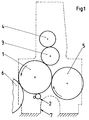
- a printing unit of a sheet-fed offset printing press essentially consists of a printing cylinder 1 which acts as an impression cylinder and which is operatively connected in a known manner to an adjacent blanket cylinder 3 and a plate cylinder 4 assigned to the blanket cylinder 3.
- a transfer drum 5 is arranged upstream of the printing cylinder 1 in the direction of sheet travel and a further transfer drum 6 is arranged downstream.
- a cleaning device 2 is to be arranged, which can be placed on and off the printing cylinder 1.
- the printing unit each has a laterally arranged machine frame 7, in which there is an opening.
- This opening serves in a known manner as a "man hole” for service work.
- Cross guides 9 running parallel to the cylinder 1 are arranged on the machine frame 7 within the opening.
- a floor conveyor 8 essentially formed from a base frame with brackets accommodates the cleaning device 2.
- the industrial conveyor 8 has a plurality of steering rollers 18 which are used for moving between the printing units.
- 9 centering rollers 17 are rotatably arranged on the industrial conveyor 8 parallel to the transverse guides.
- the industrial conveyor 8 can also be movable on an air cushion or by means of guide devices arranged, for example, in the floor area.
- An actuating device 12 is arranged on the side of each machine frame 7 below the cylinder 1. It consists essentially of a working cylinder 13 with a piston rod, which is received in a pivot joint 14. A lever 15 is also accommodated in the swivel joint 14 and has a cam roller 16 which is in contact with a longitudinal guide 11 fixed to the frame. Each lever 15 has centerings 20, to which centering means 21 arranged on the cleaning device 2 are assigned in the correct position.
- the cleaning device 2 furthermore has connections for detergent, water and energy, which are automatically coupled with corresponding counterparts at the latest in the “ready position” assigned to the cylinder 1 to be cleaned. The cleaning device is thus connected to all the supply lines required.
- the mode of operation is as follows: the cleaning device 2 is positioned on the industrial conveyor 8.
- the industrial conveyor 8 provided with steering rollers 18 is moved from one side into an opening in the machine frame 7 of the printing press into a "insertion position 10".
- the centering rollers 17 which are arranged on the industrial conveyor 8 and which engage with the transverse guides 9 fixed to the frame serve for this purpose.
- the transverse guides 9 are preferably provided on the open side with a bevel so that the industrial conveyor 8 can be accommodated in the transverse guides 9 with little effort on the end face.
- the housing of the cleaning device 2 is brought closer to the levers 15 of the first actuating device 12.
- the levers 15 have centerings which form-fit with the centering means 21 on the housing of the cleaning device 2. If a coupling has taken place between the centerings 20 and the centering means 21, the insertion position 10 has been reached.
- the first actuating device 12 now moves the cleaning device 2 along the longitudinal guides 11 by means of the lever 15 and the working cylinder 13.
- Each cam roller 16 runs on the longitudinal guide 11.
- the law of motion of the longitudinal guide 11 and lever 15 with cam roller 16 is designed such that the cleaning device 2 from the insertion position 10 (and thus also) out of the industrial conveyor 8 during the longitudinal displacement is lifted out. This clears the floor conveyor 8.
- the industrial conveyor 8 can, for example, be removed from the printing press, accommodate a further cleaning device 2 and thus feed a further printing unit.
- the actuating device 12 is activated until the cleaning device 2 has reached a standby position 19. That is, the working cylinders 13 move to a predetermined position (standby position 19) and move the levers 15 with the cleaning device 2 via the longitudinal guides 11.
- the cleaning device 2 is held in the standby position 19 by the actuating device 12. In this position 19, the cleaning device 2 is automatically connected to the connections for water, detergent and energy. If the cleaning device 2 is to clean the printing cylinder, the second actuating device 23 is activated. The working cylinder 22 lifts the cleaning device 2 via the cross member 24 around the swivel joint 14 until the cleaning device 2 rests on the pressure cylinder 1. So that the job is done, the pressure cylinder 1 can be washed in a known manner. If the cleaning device 2 is to be switched off, the rod of the working cylinder 22 is retracted and the cleaning device 2 is thus lowered into the standby position 19.
- the cleaning device 2 If the cleaning device 2 is to be replaced, for example for service purposes, it is moved back from the standby position 19 into the insertion position 10 via the longitudinal guides 11 and placed on a provided floor conveyor 8.
- the industrial truck 8 can then be laterally moved out of the opening in the machine frame 7 again.
- the same cleaning device can also be moved to another printing unit by means of industrial conveyors 8.
- the first actuating device 12 shown can alternatively also be formed by a drive motor which moves the cleaning device 2 from the insertion position 10 into the ready position 19 by means of longitudinal guides 11 by means of a cable pull.
Landscapes
- Inking, Control Or Cleaning Of Printing Machines (AREA)
- Manufacturing Of Printed Wiring (AREA)
Abstract
Description
- Die Erfindung betrifft eine Einrichtung zum Reinigen von Zylindern in Druckmaschinen mit einer an den Zylinder an- und abstellbaren Reinigungsvorrichtung.
- Aus der DE 36 14 542 A1 ist eine Einrichtung dieser Art bekannt. Diese Reinigungseinrichtung dient zum Reinigen mehrerer Zylinder innerhalb einer Rotationsdruckmaschine, indem sie mittels einer Transportvorrichtung nacheinander an mehrere Zylinder in verschiedenen Druckmashinen verfahrbar ist.
- Die Transportvorrichtung ist entlang der Druckmaschine mittels Fördermitteln in einem Führungssystem verfahrbar. Die Fördermittel sind dabei mit einer Antriebseinheit in Eingriff Nachteilig ist es dabei, daß die erforderlichen Mittel sehr aufwendig sind und der zeitliche Aufwand zwecks Verfahren der Reinigungseinrichtung von einem Druckwerk zum nächsten Druckwerk hoch ist.
- Aus der EP 0 591 634 A1 ist eine weitere Druckmaschinenzylinder-Waschvorrichtung bekannt. Diese Vorrichtung ist in eine Öffnung in einem Maschinengestell achsparallel zu einem Zylinder ein- und ausfahrbar. Die Waschvorrichtung selbst ist dabei in einer Linearführungen aufweisenden Aufhängevorrichtung aufgenommen. Die Aufhängevorrichtung besitzt stirnseitige Anschlüsse für die Ankoppelung bzw. Entkopplung von Versorgungsleitungen derart, daß bei Einschub der Waschvorrichtung automatisch eine Verbindung erzeugt wird. Die Aufhängevorrichtung mit Waschvorrichtung wird mittels Druckluftzylinder und Koppelgetriebe an den zu reinigenden Zylinder an- bzw. abgeschwenkt. Die Druckluftzylinder sowie die Aufhängevorrichtung sind in der Öffnung angeordnet und engen somit erheblich den Platz für Servicearbeiten ein. Weiterhin stellen die Linearführungen und das Koppelgetriebe eine aufwendige Lösung dar.
- Aufgabe der Erfindung ist es, eine Einrichtung zum Reinigen von Zylindern zu schaffen, die mit wenig Aufwand in eine Druckmaschine eingebaut und ausgebaut werden kann, ohne den Freiraum für Servicearbeiten ständig einzuengen.
- Erfindungsgemäß wird das dadurch gelöst, daß die positionierte Reinigungsvorrichtung auf einem Flurfördermittel seitlich zu einem zu reinigenden Zylinder durch die Öffnung einer Druckmaschine einschiebbar und auf dem Flurfördermittel herausfahrbar ist. Das Flufördermittel ist verfahrbar, so daß lediglich ein Flurfördermittel für alle Reinigungsvorrichtungen innerhalb einer Druckmaschine erforderlich ist. Am Maschinengestell sind in einer Öffnung vorzugsweise Querführungen angeordnet, (achsparallel zum Zylinder verlaufend), in die das Flurfördermittel mit Reinigungsvorrichtung in eine "Einschubposition" einschiebbar und aus dieser herausfahrbar ist. Aus der "Einschubposition" wird die das Flurfördermittel verlassende Reinigungsvorrichtung mittels einer ersten Betätigungseinrichtung über Längsführungen in eine "Bereitsschaftsposition" zum zu reinigenden Zylinder längs verschoben, d.h. in Bogenlaufrichtung oder entgegen der Bogenlaufrichtung. Mittels einer zweiten Betätigungseinrichtung wird die Reinigungsvorrichtung dann in die "Arbeitsposition" angestellt bzw. wieder in die "Bereitschaltsposition" abgestellt.
- Die erfindungsgemäße Lösung eignet sich besonders zum Reinigen von Zylindern, beispielsweise Gegendruckzylindern in Druckmaschinen. Diese Gegendruckzylinder sind aufgrund ihrer geometrischen Anordnung innerhalb der Druckmaschine schwer zugänglich. Ist die erfindungsgemäße Lösung in einer Bogendruckmaschine höherer Formatklasse eingesetzt, so weist die Reinigungsvorrichtung eine relativ hohe Masse auf. Eine solche Vorrichtung läßt sich manuell nur mit hohem Aufwand ein- oder ausbauen.
- Je nach Reinigungsprinzip eignen sich vorzugsweise Waschwalzer, z.B. Waschbürsten mit Rakel oder ein Waschtusch mit Andruckelement als Reinigungsvorrichtung. Waschwalzen oder die Waschtuchspindeln sind in stirnseitig angeordneten Seitenwänden gelagert und von einem vorzugsweise einseitig offenem Gehäuse umgeben. Den Waschwalzen bzw. dem Waschtuch sind in bekannter Weise Düsen für Waschmittel und/oder Wasser in dem Gehäuse zugeordnet. Ebenso ist vorzugsweise ein Walzenantrieb, z. B. ein Elektromotor, an dem Gehäuse angeordnet, so daß eine komplette Reinigungseinheit als Baugruppe vorliegt (einschließlich der Anschlüsse für Wasser, Waschmittel und Energie).
- Die Erfindung soll an einem Ausführungsbeispiel näher erläutert werden. Dabei zeigen schematisch:
- Fig. 1
- eine Druckeinheit einer Rotationsdruckmaschine,
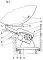
- Fig. 2
- eine Reinigungsvorrichtung in Einschubposition,
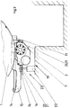
- Fig. 3
- eine Reinigungsvorrichtung in Bereitschaftsposition.
- Eine Druckeinheit einer Bogenoffsetdruckmaschine besteht im wesentlichen aus einem als Gegendruckzylinder wirkenden Druckzylinder 1, der in bekannter Weise mit einem benachbarten Gummituchzylinder 3 und einem dem Gummituchzylinder 3 zugeordneten Plattenzylinder 4 in Wirkverbindung steht. Auf die Zuordnung von Farbwerk und Feuchtwerk zum Plattenzylinder 4 soll hier nicht weiter eingegangen werden. Dem Druckzylinder 1 ist in Bogenlaufrichtung eine Transfertrommel 5 vorgeordnet und eine weitere Transfertrommel 6 nachgeordnet. Unterhalb des Druckzylinders 1 soll eine Reinigungsvorrichtung 2 angeordnet werden, die an den Druckzylinder 1 angestellt und von diesem abgestellt werden kann. Die Druckeinheit weist in bekannter Weise je ein seitlich angeordnetes Maschinengestell 7 auf, in dem eine Öffnung vorhanden ist. Diese Öffnung dient in bekannter Weise als "Mann-Loch" für Servicearbeiten. Innerhalb der Öffnung sind am Maschinengestell 7 achsparallel zum Zylinder 1 verlaufende Querführungen 9 angeordnet. Ein im wesentlichen aus einem Grundrahmen mit Halterungen gebildetes Flurfördermittel 8 nimmt die Reinigungsvorrichtung 2 auf. Das Flurfördermittel 8 besitzt mehrere Lenkrollen 18, die zum Verfahren zwischen den Druckeinheiten dienen. An dem Flurfördermittel 8 sind parallel zu den Querführungen 9 Zentrierrollen 17 drehbar angeordnet. In einer weiteren Ausbildung kann das Flurfördermittel 8 auch auf einem Luftkissen oder mittels beispielsweise im Bodenbereich angeordneten Leiteinrichtungen verfahrbar sein.
- Unterhalb des Zylinders 1 ist seitlich an jedem Maschinengestell 7 eine Betätigungsvorrichtung 12 angeordnet. Sie besteht im wesentlichen aus einem Arbeitszylinder 13 mit Kolbenstange, die in einem Drehgelenk 14 aufgenommen ist. Im Drehgelenk 14 ist ferner ein Hebel 15 aufgenommen, der eine mit einer gestellfesten Längsführung 11 in Kontakt stehende Kurvenrolle 16 aufweist. Jeder Hebel 15 weist Zentrierungen 20 auf, denen an der Reinigungsvorrichtung 2 angeordnete Zentriermittel 21 positionsgerecht zugeordnet sind. Ebenfalls unterhalb des Druckzylinders ist eine weitere gestellfeste Betätigungseinrichtung 23, bestehend aus mindestens einem Arbeitszylinder 22, der mit einer an der Reinigungsvorrichtung 2 angeordneten Traverse 24 in Eingriff steht installiert. Die Reinigungsvorrichtung 2 weist weiterhin Anschlüsse für Waschmittel, Wasser sowie Energie auf, die spätestens in der den zu reinigenden Zylinder 1 zugeordneten "Bereitschaftsposition" mit entsprechenden Gegenstücken automatisch gekuppelt werden. Damit ist die Reinigungsvorrichtung mit allen erforderlich Zuführleitungen verbunden.
- Die Wirkungsweise ist wie folgt: Auf dem Flurfördermittel 8 ist die Reinigungsvorrichtung 2 positioniert. Das mit Lenkrollen 18 versehenene Flurfördermittel 8 wird von einer Seite in eine Öffnung im Maschinengestell 7 der Druckmaschine in eine "Einschubposition 10" verfahren. Dazu dienen die an dem Flurfördermittel 8 angeordneten Zentrierrollen 17, die mit den gestellfesten Querführungen 9 in Eingriff sind. Die Querführungen 9 sind an der offenen Seite vorzugsweise mit einer Anfahrschräge versehen, so daß das Flurfördermittel 8 stirnseitig mit wenig Aufwand in die Querführungen 9 aufgenommen werden kann. Zum Erlangen der Einschubposition 10 wird das Gehäuse der Reinigungsvorrichtung 2 den Hebeln 15 der ersten Betätigungseinrichtung 12 angenähert. Die Hebel 15 weisen Zentrierungen auf, die mit Zentriermitteln 21 am Gehäuse der Reinigungsvorrichtung 2 formschlüssig übereinstimmen. Ist zwischen den Zentrierungen 20 und den Zentriermitteln 21 eine Koppelung erfolgt, so ist die Einschubposition 10 erreicht.
- Die erste Betätigungseinrichtung 12 verfährt nun mittels Hebel 15 und Arbeitszylinder 13 die Reinigungsvorrichtung 2 längs entlang auf den Langsführungen 11. Dabei läuft jede Kurvenrolle 16 auf der Längsführung 11 ab. Das Bewegungsgesetz von Längsführung 11 und Hebel 15 mit Kurvenrolle 16 ist derart ausgeführt, daß die Reinigungsvorrichtung 2 aus der Einschubposition 10 (und somit auch) aus dem Flurfördermittel 8 heraus während der Längsverschiebung herausgehoben wird. Damit wird das Flurfördermittel 8 frei. Das Flurfördermittel 8 kann beispielsweise aus der Druckmaschine entfernt werden, eine weitere Reinigungsvorrichtung 2 aufnehmen und damit eine weitere Druckeinheit beschicken. Die Betätigungsvorrichtung 12 ist bis die Reinigungsvorrichtung 2 eine Bereitschaftsposition 19 erreicht hat aktiviert. D.h. die Arbeitszylinder 13 fahren bis zu einer vorbestimmten Position (Bereitschaftsposition 19) und verschieben die Hebel 15 mit der Reinigungsvorrichtung 2 über die Längsführungen 11. Werden mehrere Betätigungsvorrichtungen 12 eingesetzt, so arbeiten diese synchron. Die Reinigungsvorrichtung 2 wird in der Bereitschaftsposition 19 durch die Betätigungseinrichtung 12 gehalten. In dieser Position 19 wird die Reinigungsvorrichtung 2 mit den Anschlüssen für Wasser, Waschmittel und Energie automatisch verbunden. Soll nun die Reinigungsvorrichtung 2 den Druckzylinder reinigen, so wird die zweite Betätigungsvorrichtung 23 aktiviert. Der Arbeitszylinder 22 hebt die Reinigungsvorrichtung 2 über die Traverse 24 um das Drehgelenk 14 aus, bis die Reinigungsvorrichtung 2 am Druckzylinder 1 anliegt. Damit ist die Anstellung erfolgt, der Druckzylinder 1 kann in bekannter Weise gewaschen werden. Soll die Reinigungsvorrichtung 2 abgestellt werden, so wird die Stange des Arbeitszylinders 22 wieder eingefahren und somit die Reinigungsvorrichtung 2 in die Bereitschaftsposition 19 abgesenkt. Soll die Reinigungsvorrichtung 2, beispielsweise zu Servicezwecken, ausgetauscht werden, wird diese aus der Bereitschaftsposition 19 in die Einschubposition 10 über die Längsführungen 11 zurückgefahren und aufein bereitgestelltes Flurfördermittel 8 abgesetzt. Das Flurfördermittel 8 kann dann seitlich aus der Öffnung am Maschinengestell 7 wieder herausgefahren werden. Die gleiche Reinigungsvorrichtung kann alternativ auch mittels Flurfördermittel 8 an eine andere Druckeinheit verfahren werden. Die dargestellte erste Betätigungsvorrichtung 12 kann alternativ auch durch einen Antriebsmotor gebildet werden, der mittels Seilzug die Reinigungsvorrichtung 2 aus der Einschubposition 10 in die Bereitschaftsposition 19 mittels Längsführungen 11 verfährt.
-
- 1
- Druckzylinder
- 2
- Reinigungsvorrichtung
- 3
- Gummituchzylinder
- 4
- Plattenzylinder
- 5
- Transfertrommel
- 6
- Transfertrommel
- 7
- Maschinengestell
- 8
- Flurfördermittel
- 9
- Querführung
- 10
- Einschubposition
- 11
- Längsführung
- 12
- Betätigungsvorrichtung
- 13
- Arbeitszylinder
- 14
- Drehgelenk
- 15
- Hebel
- 16
- Kurvenrolle
- 17
- Zentrierrolle
- 18
- Lenkrolle
- 19
- Bereitschaftsposition
- 20
- Zentrierung
- 21
- Zentriermittel
- 22
- Arbeitszylinder
- 23
- Betätigungsvorrichtung
- 24
- Traverse
Claims (4)
- Einrichtung zum Reinigen von Zylindern in Druckmaschinen, mit einer zum zu reinigenden Zylinder achsparallel ein- und ausfahrbaren sowie an diesen Zylinder an- und abstellbaren Reinigungsvorrichtung,
dadurch gekennzeichnet,
daß die auf einem Flurfördermittel (8) positionierte, achsparallel zum Zylinder in die Einschubposition (10) einer Druckmaschine einfahrbare und ausfahrbare Reinigungsvorrichtung (2) mittels gekoppelter erster Betätigungsvorrichtungen (12) über zwei gestellfeste Längsführungen (11) in eine dem Zylinder (1) zugeordnete Bereitschaftsposition (19) längsverschiebbar ist und in der Bereitschaftsposition (19) mittels mindestens einer zweiten Betätigungsvorrichtung (23) zum Zylinder (1) an- und abstellbar ist. - Einrichtung nach Anspruch 1,
dadurch gekennzeichnet,
daß am Flurfördermittel (8) Lenkrollen (18) und Zentrierrollen (17) angeordnet sind, wobei die Zentrierrollen (17) mit am Maschinengestell (7) fixierten Querführungen (9) korrespondieren. - Einrichtung nach Anspruch 1,
dadurch gekennzeichnet,
daß die erste Betätigungsvorrichtung (12) durch seitlich an jedem Maschinengestell (7) angeordnete Arbeitszylinder (13), deren Kolbenstange über ein Drehgelenk (14) mit einem Hebel (15) gekoppelt sind, gebildet ist, wobei jeder Hebel (15) Zentrierungen (20) aufweist, die mit Zentriermitteln (21) der Reinigungsvorrichtung (22) korrespondieren und mindestens eine mit einer Längsführung (11) in Eingriff stehende Kurvenrolle (16) aufweist. - Einrichtung nach Anspruch 1,
dadurch gekennzeichnet,
daß die zweite Betätigungsvorrichtung (23) durch mindestens einen am Maschinengestell (7) angeordneten mit der Reinigungsvorrichtung (2) in Eingriff bringbaren Arbeitszylinder (22) gebildet ist, der die Reinigungsvorrichtung zum Zylinder (1) an- und abstellt.
Applications Claiming Priority (2)
| Application Number | Priority Date | Filing Date | Title |
|---|---|---|---|
| DE19506640 | 1995-02-25 | ||
| DE19506640A DE19506640C2 (de) | 1995-02-25 | 1995-02-25 | Einrichtung zum Reinigen von Zylindern in Druckmaschinen |
Publications (3)
| Publication Number | Publication Date |
|---|---|
| EP0728582A2 true EP0728582A2 (de) | 1996-08-28 |
| EP0728582A3 EP0728582A3 (de) | 1996-11-20 |
| EP0728582B1 EP0728582B1 (de) | 1998-05-20 |
Family
ID=7755043
Family Applications (1)
| Application Number | Title | Priority Date | Filing Date |
|---|---|---|---|
| EP96101642A Expired - Lifetime EP0728582B1 (de) | 1995-02-25 | 1996-02-06 | Einrichtung zum Reinigen von Zylindern in Druckmaschinen |
Country Status (5)
| Country | Link |
|---|---|
| US (1) | US5615612A (de) |
| EP (1) | EP0728582B1 (de) |
| JP (1) | JP2889172B2 (de) |
| AT (1) | ATE166289T1 (de) |
| DE (2) | DE19506640C2 (de) |
Families Citing this family (10)
| Publication number | Priority date | Publication date | Assignee | Title |
|---|---|---|---|---|
| DE19753231A1 (de) * | 1997-12-01 | 1999-06-02 | Heidelberger Druckmasch Ag | Vorrichtung zur Reinigung eines Zylinders in einer Druckmaschine |
| DE19807505A1 (de) * | 1998-02-21 | 1999-08-26 | Roland Man Druckmasch | Bogenrotationsdruckmaschine mit Druckeinheiten für den Mehrfarbendruck und wenigstens einer Beschichtungseinheit |
| US6951172B2 (en) * | 1998-03-31 | 2005-10-04 | Heidelberger Druckmaschinen Ag | Accessory for a printing unit |
| DE19941943B4 (de) | 1998-10-08 | 2008-11-13 | Heidelberger Druckmaschinen Ag | Verfahren und Vorrichtung zur Entnahme einer Reinigungseinrichtung aus einer Druckmaschine |
| DE19958087B4 (de) | 1998-12-24 | 2008-07-03 | Heidelberger Druckmaschinen Ag | Verfahren zur Entnahme und zum Einsetzen einer Reinigungseinrichtung sowie Druckmaschine |
| DE10040950B4 (de) | 1999-09-15 | 2009-04-02 | Heidelberger Druckmaschinen Ag | Druckmaschine |
| DE10000558A1 (de) * | 2000-01-08 | 2001-07-12 | Baldwin Grafotec Gmbh | Wascheinrichtung für Druckmaschinenzylinder |
| DE10000554A1 (de) * | 2000-01-08 | 2001-07-12 | Baldwin Grafotec Gmbh | Waschanlage für Druckmaschinenzylinder |
| CN1853930A (zh) | 2005-04-20 | 2006-11-01 | 海德堡印刷机械股份公司 | 用于运行印刷机的方法 |
| US20080289364A1 (en) * | 2007-05-23 | 2008-11-27 | Pinkham Jr Daniel | Method and system for preheating glass batch or ingredient(s) |
Family Cites Families (13)
| Publication number | Priority date | Publication date | Assignee | Title |
|---|---|---|---|---|
| US3783782A (en) * | 1972-08-04 | 1974-01-08 | Faustel Inc | Revolving turret for supporting printing press cart |
| US3845713A (en) * | 1973-01-29 | 1974-11-05 | Pitney Bowes Inc | Automatic etcher for offset master |
| JPS5730120Y2 (de) * | 1980-01-08 | 1982-07-01 | ||
| DD227927A1 (de) * | 1984-11-02 | 1985-10-02 | Polygraph Leipzig | Vorrichtung zur reinigung eines zylinders einer druckmaschine |
| DE3614542A1 (de) * | 1986-04-29 | 1987-11-05 | Roland Man Druckmasch | Einrichtung zum waschen von zylindern in rotationsdruckmaschinen |
| DE3744800A1 (de) * | 1987-10-28 | 1989-06-29 | Spiess Gmbh G | Gummituchwaschvorrichtung |
| EP0364901B1 (de) * | 1988-10-19 | 1994-04-27 | Dai Nippon Insatsu Kabushiki Kaisha | Reinigungssystem für Bogenoffsetdruckmaschinen |
| DE3909119C2 (de) * | 1989-03-20 | 1997-01-23 | Heidelberger Druckmasch Ag | Wascheinrichtung für eine Druckmaschine |
| US5060569A (en) * | 1989-06-22 | 1991-10-29 | Didde Web Press Corporation | Apparatus for changeover of cylinders in web fed printing press |
| DE9014229U1 (de) * | 1990-10-13 | 1990-12-20 | Vliesstoff Kasper GmbH, 4050 Mönchengladbach | Umwickelvorrichtung zum Umwickeln einer Großrolle auf eine Saubertuchspindel |
| DE4215355C2 (de) * | 1992-05-13 | 1995-09-21 | Roland Man Druckmasch | Waschvorrichtung für Zylinder in Druckmaschinen, insbesondere Bogenoffsetdruckmaschinen |
| DE4233953A1 (de) * | 1992-10-08 | 1994-04-14 | Baldwin Gegenheimer Gmbh | Druckmaschinenzylinder-Waschvorrichtung |
| DK172546B1 (da) * | 1993-02-03 | 1998-12-21 | Kammann Maschf Werner | Trykkeværk med udskiftelige dele samt anordning og fremgangsmåde til udskiftning af dele i et sådant trykkeværk |
-
1995
- 1995-02-25 DE DE19506640A patent/DE19506640C2/de not_active Expired - Fee Related
-
1996
- 1996-02-06 DE DE59600204T patent/DE59600204D1/de not_active Expired - Lifetime
- 1996-02-06 AT AT96101642T patent/ATE166289T1/de active
- 1996-02-06 EP EP96101642A patent/EP0728582B1/de not_active Expired - Lifetime
- 1996-02-23 US US08/604,911 patent/US5615612A/en not_active Expired - Fee Related
- 1996-02-26 JP JP8037662A patent/JP2889172B2/ja not_active Expired - Fee Related
Also Published As
| Publication number | Publication date |
|---|---|
| DE59600204D1 (de) | 1998-06-25 |
| ATE166289T1 (de) | 1998-06-15 |
| JP2889172B2 (ja) | 1999-05-10 |
| DE19506640A1 (de) | 1996-08-29 |
| JPH08244215A (ja) | 1996-09-24 |
| US5615612A (en) | 1997-04-01 |
| EP0728582B1 (de) | 1998-05-20 |
| DE19506640C2 (de) | 1998-09-10 |
| EP0728582A3 (de) | 1996-11-20 |
Similar Documents
| Publication | Publication Date | Title |
|---|---|---|
| EP0562281B1 (de) | Vorrichtung zur wahlweisen Reinigung mehrerer Zylinder | |
| EP0749369B1 (de) | Druckwerk für eine mehrfarbenrollenrotationsdruckmaschine | |
| EP0334173B1 (de) | Vorrichtung zum Reinigen der Arbeitsflächen einer Arbeitsmaschine, insbesondere in einer Druckmaschine | |
| EP1303401B1 (de) | Druckeinheit einer offsetdruckmaschine mit trennbaren gestellmodulen | |
| DE2815388B2 (de) | Vorrichtung zum Waschen von Zylindern an Druckmaschinen, insbesondere Offsetdruckmaschinen | |
| DE4215355C2 (de) | Waschvorrichtung für Zylinder in Druckmaschinen, insbesondere Bogenoffsetdruckmaschinen | |
| DE68914934T2 (de) | Reinigungssystem für Bogenoffsetdruckmaschinen. | |
| DE19506640C2 (de) | Einrichtung zum Reinigen von Zylindern in Druckmaschinen | |
| EP1587682B1 (de) | Druckmaschinen mit mindestens einem formzylinder | |
| EP1497132A1 (de) | Lösch- und reinigungsvorrichtung für zylinder, insbesondere druckform- und gummituchzylinder einer druckmaschine | |
| DE69710929T2 (de) | Druckgruppe für rotationstiefdruckmaschine | |
| DE4326833B4 (de) | Druckmaschinenzylinder-Waschvorrichtung | |
| CH685380A5 (de) | Rotationsdruckmaschine. | |
| DE4204472C2 (de) | Walzenwechselvorrichtung | |
| EP0711666B1 (de) | Reinigungseinrichtung für eine Bogenleiteinrichtung einer Rotationsdruckmaschine | |
| DE102009058744B4 (de) | Reinigungsvorrichtung für Druck- und Druckplattenzylinder | |
| DD143157B1 (de) | Bogenbremse in bogenauslegern von bogenverarbeitenden maschinen,insbesondere druckmaschinen | |
| DD236052A1 (de) | Einrichtung zur reinigung von zylindern und walzen in druckwerken von druckmaschinen | |
| EP1188559B1 (de) | Einrichtung zum Bebildern von zylindrischen Oberflächen in Druckmaschinen | |
| DE10030027A1 (de) | Waschvorrichtung für Druckmaschinenzylinder | |
| DE19512421C2 (de) | Einrichtung zum Reinigen mehrerer Zylinder | |
| CH693029A5 (de) | Vorrichtung zum Reinigen von Leitwalzen einer Rollenrotationsdruckmaschine. | |
| EP0534929A1 (de) | Arbeitsvorrichtung mit mehreren wahlweise oder kombinierbar einzusetzenden Bearbeitungseinheiten für Bahnmaterial | |
| WO2008095551A1 (de) | Druckwerk einer rotationsdruckmaschine und ein verfahren zum waschen eines feuchtwerks eines druckwerks | |
| DE10005875A1 (de) | Farbvorratsbehälter |
Legal Events
| Date | Code | Title | Description |
|---|---|---|---|
| PUAI | Public reference made under article 153(3) epc to a published international application that has entered the european phase |
Free format text: ORIGINAL CODE: 0009012 |
|
| 17P | Request for examination filed |
Effective date: 19960216 |
|
| AK | Designated contracting states |
Kind code of ref document: A2 Designated state(s): AT BE CH DE FR GB IT LI SE |
|
| PUAL | Search report despatched |
Free format text: ORIGINAL CODE: 0009013 |
|
| AK | Designated contracting states |
Kind code of ref document: A3 Designated state(s): AT BE CH DE FR GB IT LI SE |
|
| 17Q | First examination report despatched |
Effective date: 19970310 |
|
| GRAG | Despatch of communication of intention to grant |
Free format text: ORIGINAL CODE: EPIDOS AGRA |
|
| GRAG | Despatch of communication of intention to grant |
Free format text: ORIGINAL CODE: EPIDOS AGRA |
|
| GRAH | Despatch of communication of intention to grant a patent |
Free format text: ORIGINAL CODE: EPIDOS IGRA |
|
| GRAH | Despatch of communication of intention to grant a patent |
Free format text: ORIGINAL CODE: EPIDOS IGRA |
|
| ITF | It: translation for a ep patent filed | ||
| GRAA | (expected) grant |
Free format text: ORIGINAL CODE: 0009210 |
|
| AK | Designated contracting states |
Kind code of ref document: B1 Designated state(s): AT BE CH DE FR GB IT LI SE |
|
| REF | Corresponds to: |
Ref document number: 166289 Country of ref document: AT Date of ref document: 19980615 Kind code of ref document: T |
|
| REG | Reference to a national code |
Ref country code: CH Ref legal event code: NV Representative=s name: E. BLUM & CO. PATENTANWAELTE Ref country code: CH Ref legal event code: EP |
|
| GBT | Gb: translation of ep patent filed (gb section 77(6)(a)/1977) |
Effective date: 19980520 |
|
| REF | Corresponds to: |
Ref document number: 59600204 Country of ref document: DE Date of ref document: 19980625 |
|
| ET | Fr: translation filed | ||
| PLBE | No opposition filed within time limit |
Free format text: ORIGINAL CODE: 0009261 |
|
| STAA | Information on the status of an ep patent application or granted ep patent |
Free format text: STATUS: NO OPPOSITION FILED WITHIN TIME LIMIT |
|
| 26N | No opposition filed | ||
| PGFP | Annual fee paid to national office [announced via postgrant information from national office to epo] |
Ref country code: GB Payment date: 20010112 Year of fee payment: 6 |
|
| PGFP | Annual fee paid to national office [announced via postgrant information from national office to epo] |
Ref country code: CH Payment date: 20010115 Year of fee payment: 6 |
|
| PGFP | Annual fee paid to national office [announced via postgrant information from national office to epo] |
Ref country code: AT Payment date: 20010124 Year of fee payment: 6 |
|
| PGFP | Annual fee paid to national office [announced via postgrant information from national office to epo] |
Ref country code: BE Payment date: 20010213 Year of fee payment: 6 |
|
| REG | Reference to a national code |
Ref country code: GB Ref legal event code: IF02 |
|
| PGFP | Annual fee paid to national office [announced via postgrant information from national office to epo] |
Ref country code: SE Payment date: 20020204 Year of fee payment: 7 |
|
| PG25 | Lapsed in a contracting state [announced via postgrant information from national office to epo] |
Ref country code: GB Free format text: LAPSE BECAUSE OF NON-PAYMENT OF DUE FEES Effective date: 20020206 Ref country code: AT Free format text: LAPSE BECAUSE OF NON-PAYMENT OF DUE FEES Effective date: 20020206 |
|
| PG25 | Lapsed in a contracting state [announced via postgrant information from national office to epo] |
Ref country code: LI Free format text: LAPSE BECAUSE OF NON-PAYMENT OF DUE FEES Effective date: 20020228 Ref country code: CH Free format text: LAPSE BECAUSE OF NON-PAYMENT OF DUE FEES Effective date: 20020228 Ref country code: BE Free format text: LAPSE BECAUSE OF NON-PAYMENT OF DUE FEES Effective date: 20020228 |
|
| BERE | Be: lapsed |
Owner name: MAN ROLAND DRUCKMASCHINEN A.G. Effective date: 20020228 |
|
| GBPC | Gb: european patent ceased through non-payment of renewal fee |
Effective date: 20020206 |
|
| REG | Reference to a national code |
Ref country code: CH Ref legal event code: PL |
|
| PGFP | Annual fee paid to national office [announced via postgrant information from national office to epo] |
Ref country code: FR Payment date: 20030206 Year of fee payment: 8 |
|
| PG25 | Lapsed in a contracting state [announced via postgrant information from national office to epo] |
Ref country code: SE Free format text: LAPSE BECAUSE OF NON-PAYMENT OF DUE FEES Effective date: 20030207 |
|
| EUG | Se: european patent has lapsed | ||
| PG25 | Lapsed in a contracting state [announced via postgrant information from national office to epo] |
Ref country code: FR Free format text: LAPSE BECAUSE OF NON-PAYMENT OF DUE FEES Effective date: 20041029 |
|
| REG | Reference to a national code |
Ref country code: FR Ref legal event code: ST |
|
| PGFP | Annual fee paid to national office [announced via postgrant information from national office to epo] |
Ref country code: IT Payment date: 20060228 Year of fee payment: 11 |
|
| PG25 | Lapsed in a contracting state [announced via postgrant information from national office to epo] |
Ref country code: IT Free format text: LAPSE BECAUSE OF NON-PAYMENT OF DUE FEES Effective date: 20070206 |
|
| PGFP | Annual fee paid to national office [announced via postgrant information from national office to epo] |
Ref country code: DE Payment date: 20110218 Year of fee payment: 16 |
|
| REG | Reference to a national code |
Ref country code: DE Ref legal event code: R119 Ref document number: 59600204 Country of ref document: DE Effective date: 20120901 |
|
| PG25 | Lapsed in a contracting state [announced via postgrant information from national office to epo] |
Ref country code: DE Free format text: LAPSE BECAUSE OF NON-PAYMENT OF DUE FEES Effective date: 20120901 |