EP0728596A1 - Fahrradsschnellspannvorrichtung - Google Patents
Fahrradsschnellspannvorrichtung Download PDFInfo
- Publication number
- EP0728596A1 EP0728596A1 EP95500021A EP95500021A EP0728596A1 EP 0728596 A1 EP0728596 A1 EP 0728596A1 EP 95500021 A EP95500021 A EP 95500021A EP 95500021 A EP95500021 A EP 95500021A EP 0728596 A1 EP0728596 A1 EP 0728596A1
- Authority
- EP
- European Patent Office
- Prior art keywords
- hub
- clamping
- wheel
- bicycle
- balls
- Prior art date
- Legal status (The legal status is an assumption and is not a legal conclusion. Google has not performed a legal analysis and makes no representation as to the accuracy of the status listed.)
- Withdrawn
Links
Images

Classifications
-
- B—PERFORMING OPERATIONS; TRANSPORTING
- B60—VEHICLES IN GENERAL
- B60B—VEHICLE WHEELS; CASTORS; AXLES FOR WHEELS OR CASTORS; INCREASING WHEEL ADHESION
- B60B27/00—Hubs
- B60B27/02—Hubs adapted to be rotatably arranged on axle
- B60B27/023—Hubs adapted to be rotatably arranged on axle specially adapted for bicycles
-
- B—PERFORMING OPERATIONS; TRANSPORTING
- B62—LAND VEHICLES FOR TRAVELLING OTHERWISE THAN ON RAILS
- B62K—CYCLES; CYCLE FRAMES; CYCLE STEERING DEVICES; RIDER-OPERATED TERMINAL CONTROLS SPECIALLY ADAPTED FOR CYCLES; CYCLE AXLE SUSPENSIONS; CYCLE SIDECARS, FORECARS, OR THE LIKE
- B62K25/00—Axle suspensions
- B62K25/005—Axle suspensions characterised by the axle being supported at one end only
Definitions
- Mechanisms for mounting are well known, such as the association of the hubs with the axis of the bicycle wheel.
- the object of the invention is to develop a clamping device making it possible to adjust without any play, and at the whim of the user, the clamping elements, either during assembly, or subsequently, in the event of adjustment from use, by manual adjustment by slight axial displacement between the clamping system relative to the wheel axle.
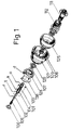
- Figure 1 consists of an isometric breakdown of all the parts making up a practical embodiment of the rapid clamping mechanism, the subject of the invention.
- Figure 2 consists of an exploded view of another practical embodiment of the mechanism which is the subject of the invention.
- the device (104) is housed inside the hub (127) to which it is retained by the washer (108) in the base (a).
- the axis (102) is housed inside the device, the function of the first being to bring out or not the balls (101) through the tightening holes (0) (104), depending on their relative position.
- the axis in question (102) comprises a flap (r) intended to accommodate the balls (101).
- the balls (101) are forced to come out of their housing in the flap (r) in order to be placed on the largest diameter of the axis, in front, so, come out through the tightening holes (0) (104).
- the push button (106) is screwed at the end of the clamping pin (102). Its function is to move the clamping axis (102) in axial direction relative to the device (104) in order to make the flaps (r) of the axis coincide with the holes (0) of the closure. So that the balls (101) go to lodge in said flaps (r) while remaining flush with the tightening holes (0).
- the clamping axis (102) returns to the normal position due to the action of the spring (105). The balls (101), in this position, are forced out of the flaps (r), and appear through the holes (0) of the device (104).
- the axis (102), its flaps (r), balls (101), tightening holes (0) (104), housing of the device (104) on the axle (111) of the bicycle, etc., is identical to that already explained for the variant of FIG. 1.
- Threaded at one end of the clamping axis (102) is the butterfly (106). Its function is to rotate the device (104) relative to the adjustment system (B1) so that all of these tightenings can lengthen or shorten as the user wishes, in order to avoid d 'possible play in the wheel. To do this, the outer surface (s) of the locking pin (102) fits into the inner surface of the device (104), without it being possible to rotate it, for example, the two surfaces having in this respect a polygonal section.
- This butterfly (E) can, moreover, move in the axial direction the locking axis (102) relative to the devices (104) and (B1) where it will be housed. It thus displaces the flaps (r) of the axis (102) with respect to the tightening holes (0) (104) by ensuring that the balls (c) come out or not through these holes depending on their position.
- the springs (105) located on both sides of the axis (102) ensure that the balls, in the rest position, always come out through the tightening holes (0) (104) in a similar way to that described previously.
- This mechanism is identical for the front and rear wheels, except that for the latter the rear axle (111) is mounted.
- This axle has a thread on its rear part, in order to place the toothed plates of the bicycle there.
- the drum (125) is screwed to the front and rear axles (111). It is he who is responsible for transmitting the rotation to the wheel and serving as a braking surface. For this purpose, it internally houses the drum brakes.
Landscapes
- Engineering & Computer Science (AREA)
- Mechanical Engineering (AREA)
- Axle Suspensions And Sidecars For Cycles (AREA)
Priority Applications (1)
| Application Number | Priority Date | Filing Date | Title |
|---|---|---|---|
| EP95500021A EP0728596A1 (de) | 1995-02-24 | 1995-02-24 | Fahrradsschnellspannvorrichtung |
Applications Claiming Priority (1)
| Application Number | Priority Date | Filing Date | Title |
|---|---|---|---|
| EP95500021A EP0728596A1 (de) | 1995-02-24 | 1995-02-24 | Fahrradsschnellspannvorrichtung |
Publications (1)
| Publication Number | Publication Date |
|---|---|
| EP0728596A1 true EP0728596A1 (de) | 1996-08-28 |
Family
ID=8221645
Family Applications (1)
| Application Number | Title | Priority Date | Filing Date |
|---|---|---|---|
| EP95500021A Withdrawn EP0728596A1 (de) | 1995-02-24 | 1995-02-24 | Fahrradsschnellspannvorrichtung |
Country Status (1)
| Country | Link |
|---|---|
| EP (1) | EP0728596A1 (de) |
Citations (2)
| Publication number | Priority date | Publication date | Assignee | Title |
|---|---|---|---|---|
| FR2588513A1 (fr) * | 1985-10-14 | 1987-04-17 | Rousson Chamoux Sa | Moyeu perfectionne a demontage rapide, notamment pour fauteuils pour handicapes physiques |
| EP0612629A2 (de) * | 1993-02-23 | 1994-08-31 | Antonio Guerra Navas | Fahrradnocke |
-
1995
- 1995-02-24 EP EP95500021A patent/EP0728596A1/de not_active Withdrawn
Patent Citations (2)
| Publication number | Priority date | Publication date | Assignee | Title |
|---|---|---|---|---|
| FR2588513A1 (fr) * | 1985-10-14 | 1987-04-17 | Rousson Chamoux Sa | Moyeu perfectionne a demontage rapide, notamment pour fauteuils pour handicapes physiques |
| EP0612629A2 (de) * | 1993-02-23 | 1994-08-31 | Antonio Guerra Navas | Fahrradnocke |
Similar Documents
| Publication | Publication Date | Title |
|---|---|---|
| FR2597058A1 (fr) | Dispositif de serrage a liberation rapide pour moyeu de bicyclette | |
| CA2109988C (fr) | Procede et dispositif de freinage notamment pour cycles | |
| US4079958A (en) | Hub anti-escape device for a bicycle | |
| FR2624452A1 (fr) | Organe de fixation et d'articulation notamment pour dispositif de reglage d'un element optique en particulier pour projecteur de vehicule automobile | |
| EP0417265B1 (de) | Tragbares datenverarbeitungsgerät mit einem schwenkbaren bildschirm | |
| FR2485657A1 (fr) | Dispositif de verrouillage d'un ecrou sur un arbre | |
| EP0703376A2 (de) | Fahrradnabe mit Freilauf | |
| FR2614596A1 (fr) | Pedale de bicyclette | |
| EP1241072A1 (de) | Verbindung eines Lenksäulenbügels mit einem Kraftfahrzeuglenkungsritzel | |
| FR2736033A1 (fr) | Dispositif d'entrainement a roue libre, notamment pour une bicyclette | |
| FR2716422A1 (fr) | Dispositif de fixation d'un cycle pour un porte-cycle et porte-cycle comprenant un tel dispositif. | |
| FR2720537A1 (fr) | Système de montage réglable de roue de machine à sous. | |
| FR2518461A1 (fr) | Nouveau montage de la roue motrice d'un cycle ou d'un motocycle entre les branches de la fourche arriere dudit cycle | |
| EP0612629B1 (de) | Fahrradnocke | |
| FR2680746A1 (fr) | Moyeu arriere en plusieurs parties pour bicyclettes. | |
| EP1556243A1 (de) | Vorrichtung zum verriegeln der konfiguration einer einrichtung,wie zum beispiel eines fahrzeugsitzes | |
| FR2679173A1 (fr) | Dispositif pour la commande de l'echappement d'une enceinte pneumatique sous pression. | |
| FR2671312A1 (fr) | Moyeu de roue a demontage rapide perfectionne pour vehicules legers. | |
| CH690985A5 (fr) | Dispositif de freinage. | |
| EP0993402B1 (de) | Nabenmontagevorrichtung für zweirad | |
| FR2493441A1 (fr) | Frein a disque a selle coulissante a commande mecanique | |
| FR2525536A1 (de) | ||
| BE435289A (de) | ||
| FR2772329A1 (fr) | Dispositif mecanique de desserrage de secours pour la commande a distance d'etriers de freins hydrauliques | |
| FR2547247A1 (fr) | Dispositif de guidage pour la mise en place d'une roue sur l'essieu d'un vehicule automobile |
Legal Events
| Date | Code | Title | Description |
|---|---|---|---|
| PUAI | Public reference made under article 153(3) epc to a published international application that has entered the european phase |
Free format text: ORIGINAL CODE: 0009012 |
|
| AK | Designated contracting states |
Kind code of ref document: A1 Designated state(s): AT BE CH DE DK FR GB GR IE IT LI LU MC NL PT SE |
|
| 17P | Request for examination filed |
Effective date: 19961022 |
|
| GRAG | Despatch of communication of intention to grant |
Free format text: ORIGINAL CODE: EPIDOS AGRA |
|
| 17Q | First examination report despatched |
Effective date: 19971211 |
|
| GRAG | Despatch of communication of intention to grant |
Free format text: ORIGINAL CODE: EPIDOS AGRA |
|
| GRAH | Despatch of communication of intention to grant a patent |
Free format text: ORIGINAL CODE: EPIDOS IGRA |
|
| STAA | Information on the status of an ep patent application or granted ep patent |
Free format text: STATUS: THE APPLICATION IS DEEMED TO BE WITHDRAWN |
|
| 18D | Application deemed to be withdrawn |
Effective date: 19980514 |