EP0728689A2 - Blattzuführvorrichtung - Google Patents
Blattzuführvorrichtung Download PDFInfo
- Publication number
- EP0728689A2 EP0728689A2 EP96102489A EP96102489A EP0728689A2 EP 0728689 A2 EP0728689 A2 EP 0728689A2 EP 96102489 A EP96102489 A EP 96102489A EP 96102489 A EP96102489 A EP 96102489A EP 0728689 A2 EP0728689 A2 EP 0728689A2
- Authority
- EP
- European Patent Office
- Prior art keywords
- sheet
- sheet supply
- separation pad
- sheets
- supply apparatus
- Prior art date
- Legal status (The legal status is an assumption and is not a legal conclusion. Google has not performed a legal analysis and makes no representation as to the accuracy of the status listed.)
- Granted
Links
- 238000000926 separation method Methods 0.000 claims abstract description 86
- 238000011144 upstream manufacturing Methods 0.000 claims abstract description 9
- 238000000034 method Methods 0.000 claims description 11
- 238000005452 bending Methods 0.000 claims description 2
- 238000009835 boiling Methods 0.000 claims description 2
- 238000010438 heat treatment Methods 0.000 claims description 2
- 238000007667 floating Methods 0.000 description 6
- 238000001514 detection method Methods 0.000 description 5
- 238000010276 construction Methods 0.000 description 2
- 239000002649 leather substitute Substances 0.000 description 2
- 238000007639 printing Methods 0.000 description 2
- 230000001105 regulatory effect Effects 0.000 description 2
- 239000005060 rubber Substances 0.000 description 2
- 239000000853 adhesive Substances 0.000 description 1
- 230000001070 adhesive effect Effects 0.000 description 1
- 230000001276 controlling effect Effects 0.000 description 1
- 239000007799 cork Substances 0.000 description 1
- 238000007599 discharging Methods 0.000 description 1
- 239000006185 dispersion Substances 0.000 description 1
- 239000013013 elastic material Substances 0.000 description 1
- 239000000463 material Substances 0.000 description 1
- 230000002093 peripheral effect Effects 0.000 description 1
- 239000002985 plastic film Substances 0.000 description 1
- 229920006255 plastic film Polymers 0.000 description 1
- 229920003002 synthetic resin Polymers 0.000 description 1
- 239000000057 synthetic resin Substances 0.000 description 1
Images






Classifications
-
- B—PERFORMING OPERATIONS; TRANSPORTING
- B65—CONVEYING; PACKING; STORING; HANDLING THIN OR FILAMENTARY MATERIAL
- B65H—HANDLING THIN OR FILAMENTARY MATERIAL, e.g. SHEETS, WEBS, CABLES
- B65H3/00—Separating articles from piles
- B65H3/02—Separating articles from piles using friction forces between articles and separator
- B65H3/06—Rollers or like rotary separators
- B65H3/0607—Rollers or like rotary separators cooperating with means for automatically separating the pile from roller or rotary separator after a separation step
-
- B—PERFORMING OPERATIONS; TRANSPORTING
- B65—CONVEYING; PACKING; STORING; HANDLING THIN OR FILAMENTARY MATERIAL
- B65H—HANDLING THIN OR FILAMENTARY MATERIAL, e.g. SHEETS, WEBS, CABLES
- B65H1/00—Supports or magazines for piles from which articles are to be separated
- B65H1/04—Supports or magazines for piles from which articles are to be separated adapted to support articles substantially horizontally, e.g. for separation from top of pile
-
- B—PERFORMING OPERATIONS; TRANSPORTING
- B65—CONVEYING; PACKING; STORING; HANDLING THIN OR FILAMENTARY MATERIAL
- B65H—HANDLING THIN OR FILAMENTARY MATERIAL, e.g. SHEETS, WEBS, CABLES
- B65H3/00—Separating articles from piles
- B65H3/46—Supplementary devices or measures to assist separation or prevent double feed
- B65H3/52—Friction retainers acting on under or rear side of article being separated
- B65H3/5207—Non-driven retainers, e.g. movable retainers being moved by the motion of the article
- B65H3/5215—Non-driven retainers, e.g. movable retainers being moved by the motion of the article the retainers positioned under articles separated from the top of the pile
- B65H3/5223—Retainers of the pad-type, e.g. friction pads
-
- B—PERFORMING OPERATIONS; TRANSPORTING
- B65—CONVEYING; PACKING; STORING; HANDLING THIN OR FILAMENTARY MATERIAL
- B65H—HANDLING THIN OR FILAMENTARY MATERIAL, e.g. SHEETS, WEBS, CABLES
- B65H2405/00—Parts for holding the handled material
- B65H2405/10—Cassettes, holders, bins, decks, trays, supports or magazines for sheets stacked substantially horizontally
- B65H2405/11—Parts and details thereof
- B65H2405/111—Bottom
- B65H2405/1118—Areas with particular friction properties, e.g. friction pad arrangement
Definitions
- the present invention relates to a sheet supply apparatus for supplying a sheet (for example, printing sheet, transfer sheet, photosensitive sheet, electrostatic recording sheet, print sheet, OHP sheet, envelope, post card, sheet original and the like) from a sheet stacking portion to a sheet treating portion (for example, recording portion, reading portion, working portion and the like) in an image forming apparatus such as a recording device, i.e., a printer (as an information output device of a word processor, a personal computer and the like), a copying machine, a facsimile machine and the like, and a recording apparatus having such a sheet supply apparatus.
- a recording device i.e., a printer (as an information output device of a word processor, a personal computer and the like), a copying machine, a facsimile machine and the like, and a recording apparatus having such a sheet supply apparatus.
- a sheet stacking plate 201 for stacking sheets thereon is biased upwardly by a spring member 203.
- a free roller 204 for regulating an upper surface of the sheet stack is contacted with an upper surface of the sheet stack on the sheet stacking plate 201 to maintain the upper surface of the sheet stack below a guide surface 205.
- an inclined surface 207 for separating sheets is disposed at a downstream side of the sheet stacking plate 201.
- a sheet supply roller 206 is constituted by a semi-circular roller having a large diameter portion and a small diameter portion (cut-out portion) so that, when the large diameter portion of the sheet supply roller is urged against an upper surface of the sheet stack on the sheet stacking plate 201, one or several sheets are fed out.
- the sheets fed out by the sheet supply roller 206 abut against the inclined surface 207.
- an uppermost sheet rides over the inclined surface 207 while being flexed, thereby separating the uppermost sheet from the other sheet(s). Since tip ends of second and other sheets are pressed downwardly by an elastic force of the flexed uppermost sheet, these sheets cannot ride over the inclined surface 207. In this way, the sheets are positively separated one by one.
- the inclination of the inclined surface when the sheets having great flexural rigidity are separated, the inclination of the inclined surface must be set smaller so that the fed out sheet is not deformed or folded; whereas, when the sheets having small flexural rigidity are separated, the inclination of the inclined surface must be set greater so that the second and other sheets can be fully held by the elastic force of the flexed uppermost sheet.
- the inclination of the inclined surface 207 is set greater to separate the sheets (for example, envelopes, post cards and the like) having great flexural rigidity, for example, when copying sheets having a weight of 60 - 100 g/m 2 try to be separated, the second and other sheets cannot be adequately held by the elastic force of the flexed uppermost sheet, with the result that the double-feed of sheets may occur.
- the sheet having small flexural rigidity such as plain sheet.
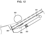
- a sheet stacking plate 301 on which sheets are stacked as a sheet stack is biased upwardly by a spring 302 so that, when a sheet supply roller 303 is contacted with an uppermost sheet in the sheet stack, several sheets are fed out by rotation of the sheet supply roller.
- An elastically deformable plate member 305 is disposed at a position where tip ends of the stacked sheets is regulated.
- the plate member 305 is formed from a plastic film or a metallic spring plate having predetermined flexural rigidity and can be elastically deformed when the sheets fed out by the sheet supply roller 303 abuts against the plate member.
- separation pads 306 for generating a double-feed preventing force by contacting with a last sheet are provided on a sheet stacking surface of the sheet stacking plate 302.
- the separation pads 306 are normally formed from elastic material such as rubber, artificial leather or the like.
- the separation pads 306 may be elastically deformed to float. If the separation pads are deformed in this way, as shown in Fig. 13, the tip ends of the sheets are lifted, with the result that the deforming start position of the plate member 305 is elevated.
- the deforming start position is elevated, an amount of deformation of the plate member 305 is increased, with the result that two or more sheets may ride over the plate member simultaneously, thereby causing the double-feed.
- the separation pads 306 are formed from material which is hard to be elastically deformed, due to inaccurate parallelism of the sheet stacking surface of the sheet stacking plate 302 and/or dispersion in thickness of the separation pads 306, the above-mentioned phenomenon (floating of the separation pad or pads) may occur, thereby causing the double-feed. Thus, this attempt is still unsatisfactory.
- the present invention aims to eliminate the above-mentioned conventional drawbacks, and an object of the present invention is to positively prevent double-feed of sheets due to deformation of separation pad or pads provided on a sheet stacking plate.
- a sheet supply apparatus comprising a sheet stacking means for stacking sheets, a sheet supply means for feeding out the sheets stacked on the sheet stacking means, a separation means for separating the sheets fed out by the sheet supply means one by one, and a friction separation pad means provided on a sheet stacking surface of the sheet stacking means in a confronting relation to the sheet supply means.
- the separation pad means is so shaped that a surface of the separation pad means opposed to the sheet supply means has an upstream side high level surface portion and a downstream side low level portion in a sheet supplying direction.
- the present invention further provides a recording apparatus comprising a sheet stacking means for stacking sheets, a sheet supply means for feeding out the sheets stacked on the sheet stacking means, a separation means for separating the sheets fed out by the sheet supply means one by one, a recording means for executing recording on the sheet separated by the separation means, and a friction separation pad means provided on a sheet stacking surface of the sheet stacking means in a confronting relation to the sheet supply means.
- the separation pad means is so shaped that a surface of the separation pad means opposed to the sheet supply means has an upstream side high level surface portion and a downstream side low level portion in a sheet supplying direction.
- the apparatus can be made compact and cheaper without reducing the separating ability of the separation pad means.
- Fig. 1 is a perspective view of the entire recording apparatus A having a sheet supply apparatus B according to the present invention.
- a paper tray 1 also acts as a cover of the recording apparatus A and can be rotated around a rotary shaft (not shown) in a direction shown by the double-headed arrow. In use, the paper tray 1 is opened as shown in Fig. 1. One or more sheets are set on the paper tray 1 with tip ends of the sheets being inserted into sheet supply opening 7. In this condition, the sheets are separated one by one by the sheet supply apparatus B disposed within the recording apparatus and the separated sheet is supplied to a recording portion C.
- a paper guide 2 can be slid left and right with predetermined friction to regulate side edges of the sheets stacked on the paper tray 1, thereby aligning the sheets.
- Key-tops 3 for handling the recording apparatus A include tact-switches for effecting ON/OFF of a power source, a sheet supplying operation, a sheet discharging operation and the like.
- a display 4 serves to display a sheet operating condition, a sheet setting condition, an error mode and the like.
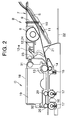
- Fig. 2 is a sectional view of the recording apparatus A.
- a sheet stacking means for stacking the sheets S is constituted by a pressure plate 10 which is biased upwardly (Fig. 2) by pressure springs 9.
- a pick-up roller (sheet supply means) 8 is disposed in a confronting relation to an uppermost sheet in the sheet stack S.
- the pick-up roller 8 is a so-called semi-circular roller having a cut-out portion, and, by waiting the pick-up roller in a condition as shown in Fig. 2, the sheet setting ability is improved.
- a separation pad 11 having predetermined coefficient of friction is attached to a sheet stacking surface of the pressure plate 10 by adhesive and the like so that the separation pad is contacted with a lowermost sheet in the sheet stack.
- the coefficient of friction of the separation pad is so selected that friction coefficient ⁇ SS between the sheets becomes smaller than friction coefficient ⁇ SP between the separation pad 11 and the sheet and friction coefficient ⁇ SR between the pick-up roller 8 and the sheet becomes greater than the friction coefficient ⁇ SP. Namely, ⁇ SS ⁇ ⁇ SP ⁇ SR
- the number of sheets stacked on the pressure plate becomes few, it is possible to prevent the double-feed phenomenon that the lowermost sheet is fed out together with the sheet being fed by the pick-up roller 8.
- a separation means for separating the sheets one by one is constituted by a plate member 21.
- the plate member 21 is elastically deformed when it is urged by the sheets fed by the pick-up roller 8, with the result that, when the uppermost sheet ridges over the deformed plate member 21, the uppermost sheet is separated from the other sheets.
- the plate member 21 is formed from synthetic resin film such as Myler.
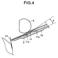
- the separation pad 11 has an inverted V-shaped section including a central portion protruded above the sheet stacking surface of the pressure plate 10 and is attached to the pressure plate 10 in such a manner that a surface 11a of a front portion of the separation pad 11 is inclined with respect to the sheet stacking surface of the pressure plate 10 by an angle of ⁇ . Further, the pick-up roller 8 is disposed in a confronting relation to the front surface 11a of the separation pad 11 inclined by the angle of ⁇ .
- the sheet urged against the rotating pick-up roller 8 by the biasing forces of the pressure springs 9 and fed out by the pick-up roller is guided along the front surface 11a by the angle of ⁇ .
- the fed sheet is not floating and abuts against the plate member 21 at a substantially constant position along the sheet stack. Accordingly, the deformed amount of the plate member 21 is stabilized, thereby preventing the poor sheet supply such as double-feed.
- a surface 11b of a rear (i.e. downstream) portion of the separation pad 11 is inclined in an direction opposite to the inclining direction of the front surface 11a, so that, when sheets are loaded on the pressure plate 10, even if the sheets are inserted along the sheet stacking surface of the pressure plate 10, the tip ends of the sheets cannot be caught by the rear end of the separation pad 11, and the sheets are surely loaded on the pressure plate since the tip ends of the sheets can easily ride over the separation pad 11 along the rear surface 11b.
- a width of the separation pad 11 is set to be smaller than a width of the pick-up roller 8, due to the compactness of the separation pad, the apparatus can be made cheaper, and the coefficient of friction of the separation pad 11 and the sheet can be made optimum and side edges of the separation pad 11 can contribute to separate the sheets, thereby obtaining the stable sheet separating ability.
- the separation pad 11 is formed from a plate-shaped elastic member made of rubber, artificial leather, cork or the like and is attached to the pressure plate while bending the plate-shaped elastic member, the plate-shaped elastic member may be previously bent.
- a pair of discharge rollers 20 arranged along a sheet conveying direction, and a pair of discharge pinch rollers 16 disposed below the respective discharge rollers 20 and urged against the respective discharge rollers by corresponding discharge coil springs 17.
- a panel board 23 positioned near an operation surface.
- the panel board 23 is disposed immediately below the key-tops 3 so that force applied to the key-tops 3 are converted into electrical signals by detectors (not shown) on the panel board 23 for commanding the respective operations.
- a paper sensor 12 is attached to the panel board 23, which paper sensor 12 serves to emit a detection signal in response to rotation of a paper sensor lever 12a protruded into a sheet path. Now, a relation between the paper sensor 12 and the LF roller 13.
- the sheet fed out by the pick-up roller 8 and separated by the plate member 21 rotates the paper sensor lever 12a, with the result that the detection signal (for sheet) is outputted from the paper sensor 12.
- the sheet On the basis of this detection signal, by rotating the pick-up roller 8 by a predetermined amount, the sheet reaches the LF roller 13. In this case, by stopping the LF roller 13 or by rotating the LF roller in a reverse direction, the tip end of the fed sheet abuts against a nip between the LF roller 13 and the pinch roller 14 to form a loop in the sheet, thereby correcting the skew-feed of the sheet (registration operation).
- the sheet When the sheet is conveyed on the basis of the detection signal of the paper sensor 12 in this way, the sheet can be fed out with a correct distance between the LF roller and the pick-up roller, thereby avoiding a danger that the sheet does not reach the LF roller (and, thus, the skew-feed cannot be corrected) or the sheet is execessively penetrated into the nip to fold the sheet.
- a carriage 19 on which the print head 18 is mounted is slidably supported on a guide shaft 31 disposed on a chassis 24 along a longitudinal direction thereof and is driven by a carriage motor (not shown) and a carriage belt (not shown) in response to a recording signal.
- An HP sensor 28 for positioning the carriage 19 is attached to a carrier running portion of the chassis 24.
- the HP sensor comprises a photo-interrupter of permeable type which serves to detect the passing of a light shield plate of the carriage 19, thereby detecting the position of the carriage 19.
- the print head 18 is electrically connected to a controller board 22 (Fig. 2) through a carriage flexible cable 32 so that the recording operation of the print head 18 is effected in response to a signal from the controller board 22.
- the recording method of the print head 18 is an ink jet recording method in which a selected electro-thermal converter is energized in response to the recording signal and, by growing a bubble in ink by heating the ink to exceed film boiling by means of the energized electro-thermal converter, the ink is discharged from a discharge opening, thereby executing the recording.
- the sheets stacked on the pressure plate 10 are fed out by the pick-up roller 8 to reach the plate member 21.
- the plate member is deformed and the uppermost sheet rides over the plate member, the uppermost sheet is Separated from the other sheets.
- the separated and conveyed sheet is detected by the paper sensor 12, and, after detection, the sheet is conveyed by the predetermined amount, thereby correcting the skew-feed of the sheet by the LF roller 13.
- the sheet After the sheet is conveyed toward the discharge roller 16 and the registration of the sheet is completed, the sheet is further conveyed; meanwhile, the recording is effected on the sheet by means of the print head 18. After recording, the sheet is discharged out of the recording apparatus through the discharge opening 6 by means of the discharge rollers 16.
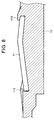
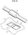
- the separation pad 11 is secured to the pressure plate 10 while deforming a plate-shaped member into an inverted V-shape. If the separation pad 11 is merely adhered to the sheet stacking surface of the pressure plate 10, when the sheet is fed out by the pick-up roller 8, the end of the sheet will be floating to float the entire sheet and/or the separation pad 18 itself will be peeled from the pressure plate. To avoid this, in the second embodiment, front and rear ends of the separation pad 11 are held by shelves 111, 112 formed on the pressure plate 10.
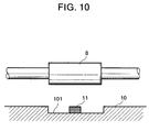
- a recess 101 is formed in the pressure plate 10 in a confronting relation to the pick-up roller 8.
- the separation pad 11 is secured within the recess 101 while deforming it into an inverted V-shaped as is in the second embodiment.
- the front and rear ends of the separation pad 11 is held by the shelves 111, 112 formed on the pressure plate 10, thereby preventing the peeling of the separation pad.
- the pick-up roller 8 Since the recess 101 has a dimension capable of receiving the pick-up roller 8, the pick-up roller 8 is not contacted with the sheet stacking surface of the pressure plate 10. Accordingly, when the sheets are urged against the pick-up roller 8 by the pressure springs 9, the load from the pressure springs 9 positively acts on the separation pad 11, with the result that the adequate friction force can be applied to the last sheet, thereby surely preventing the double-feed.
- the front end of the sheet can be prevented from floating.
- the sheet can reach the proper position on the separation means to reduce the occurrence of the poor separation of the separation means, the stable sheet supply can be realized and the reliable sheet supply apparatus can be provided.
- the present invention provides a sheet supply apparatus comprising sheet stacking means for stacking sheets, sheet supply means for feeding out the sheets stacked on the sheet stacking means, separation means for separating the sheets fed out by the sheet supply means one by one, and friction separation pad means provided on a sheet stacking surface of the sheet stacking means in a confronting relation to the sheet supply means.
- the separation pad means is so constructed that a surface of the separation pad means opposed to the sheet supply means has an upstream side high level surface portion and a downstream side low level portion in a sheet supplying direction.
Landscapes
- Engineering & Computer Science (AREA)
- Mechanical Engineering (AREA)
- Sheets, Magazines, And Separation Thereof (AREA)
- Handling Of Cut Paper (AREA)
Applications Claiming Priority (3)
| Application Number | Priority Date | Filing Date | Title |
|---|---|---|---|
| JP03219395A JP3313927B2 (ja) | 1995-02-21 | 1995-02-21 | シート材給送装置及び記録装置 |
| JP3219395 | 1995-02-21 | ||
| JP32193/95 | 1995-02-21 |
Publications (3)
| Publication Number | Publication Date |
|---|---|
| EP0728689A2 true EP0728689A2 (de) | 1996-08-28 |
| EP0728689A3 EP0728689A3 (de) | 1997-04-16 |
| EP0728689B1 EP0728689B1 (de) | 2002-06-05 |
Family
ID=12352075
Family Applications (1)
| Application Number | Title | Priority Date | Filing Date |
|---|---|---|---|
| EP96102489A Expired - Lifetime EP0728689B1 (de) | 1995-02-21 | 1996-02-19 | Blattzuführvorrichtung |
Country Status (4)
| Country | Link |
|---|---|
| US (1) | US5951003A (de) |
| EP (1) | EP0728689B1 (de) |
| JP (1) | JP3313927B2 (de) |
| DE (1) | DE69621487T2 (de) |
Cited By (1)
| Publication number | Priority date | Publication date | Assignee | Title |
|---|---|---|---|---|
| US6550991B2 (en) | 2001-03-22 | 2003-04-22 | Electronics For Imaging, Inc. | Paper tray adjustment page |
Families Citing this family (13)
| Publication number | Priority date | Publication date | Assignee | Title |
|---|---|---|---|---|
| US6105954A (en) * | 1997-10-15 | 2000-08-22 | Howtek, Inc. | Sheet feeder for digitizing scanner |
| CN1200863C (zh) * | 2000-04-06 | 2005-05-11 | 株式会社理光 | 送纸装置及图像形成装置 |
| US6932529B2 (en) * | 2002-08-13 | 2005-08-23 | Hewlett-Packard Development Company, L.P. | Method and systems for accessing a separation pad in a printing device |
| TWI302518B (en) * | 2006-06-26 | 2008-11-01 | Lite On Technology Corp | Object-feeding system |
| JP4306738B2 (ja) * | 2007-02-14 | 2009-08-05 | コニカミノルタビジネステクノロジーズ株式会社 | 給紙装置およびそれに用いられる給紙カセット,画像形成装置 |
| US7866658B2 (en) * | 2007-09-24 | 2011-01-11 | Hewlett-Packard Development Company, L.P. | Media pick system and method |
| JP2010013208A (ja) * | 2008-07-01 | 2010-01-21 | Ricoh Co Ltd | 給紙装置、及び画像形成装置 |
| CN101659358B (zh) * | 2008-08-27 | 2012-03-28 | 鸿富锦精密工业(深圳)有限公司 | 压纸装置 |
| TWM363391U (en) * | 2009-03-19 | 2009-08-21 | Cal Comp Electronics & Comm Co | Paper feeding module and multi-function peripheral having the same |
| TWI408097B (zh) * | 2010-01-08 | 2013-09-11 | Primax Electronics Ltd | 自動饋紙裝置 |
| JP5821423B2 (ja) * | 2011-08-31 | 2015-11-24 | ブラザー工業株式会社 | シート搬送装置及び画像形成装置 |
| JP7225365B2 (ja) * | 2017-08-31 | 2023-02-20 | キヤノン株式会社 | シート給送装置及び画像形成装置 |
| JP7005234B2 (ja) * | 2017-08-31 | 2022-01-21 | キヤノン株式会社 | シート給送装置及び画像形成装置 |
Family Cites Families (15)
| Publication number | Priority date | Publication date | Assignee | Title |
|---|---|---|---|---|
| US3687448A (en) * | 1970-12-28 | 1972-08-29 | Xerox Corp | Sheet feeding apparatus |
| US4089516A (en) * | 1977-04-18 | 1978-05-16 | International Business Machines Corporation | Multibin, cut-sheet xerographic copier |
| JPS6155038A (ja) * | 1984-08-24 | 1986-03-19 | Canon Inc | シ−ト状材料給送装置 |
| US4635922A (en) * | 1984-10-29 | 1987-01-13 | Pitney Bowes Inc. | Envelope feeding apparatus |
| JPS62140041U (de) * | 1986-02-28 | 1987-09-03 | ||
| JPS62249841A (ja) * | 1986-04-23 | 1987-10-30 | Matsushita Graphic Commun Syst Inc | 自動給紙装置 |
| JPS644537A (en) * | 1987-06-25 | 1989-01-09 | Toyota Motor Corp | Differential motion control device |
| JPH01321230A (ja) * | 1988-06-23 | 1989-12-27 | Canon Inc | シート材1枚分離供給装置 |
| US5088715A (en) * | 1989-07-18 | 1992-02-18 | Konica Corporation | Manual paper feed apparatus having a yieldable separating member |
| US5183248A (en) * | 1989-08-28 | 1993-02-02 | Mita Industrial Co., Ltd. | Sheet feeding device |
| US5026042A (en) * | 1990-01-22 | 1991-06-25 | Xerox Corporation | Sheet feeder for copiers and printers |
| JPH04256638A (ja) * | 1991-02-06 | 1992-09-11 | Canon Inc | 給紙装置 |
| US5437444A (en) * | 1992-03-12 | 1995-08-01 | Canon Kabushiki Kaisha | Sheet supplying apparatus |
| JPH05278883A (ja) * | 1992-03-31 | 1993-10-26 | Canon Inc | シート分離装置 |
| US5316285A (en) * | 1993-04-30 | 1994-05-31 | Hewlett-Packard Company | Sheet media realignment mechanism |
-
1995
- 1995-02-21 JP JP03219395A patent/JP3313927B2/ja not_active Expired - Fee Related
-
1996
- 1996-02-19 EP EP96102489A patent/EP0728689B1/de not_active Expired - Lifetime
- 1996-02-19 DE DE69621487T patent/DE69621487T2/de not_active Expired - Fee Related
-
1997
- 1997-11-28 US US08/980,209 patent/US5951003A/en not_active Expired - Fee Related
Cited By (1)
| Publication number | Priority date | Publication date | Assignee | Title |
|---|---|---|---|---|
| US6550991B2 (en) | 2001-03-22 | 2003-04-22 | Electronics For Imaging, Inc. | Paper tray adjustment page |
Also Published As
| Publication number | Publication date |
|---|---|
| JPH08225172A (ja) | 1996-09-03 |
| JP3313927B2 (ja) | 2002-08-12 |
| EP0728689A3 (de) | 1997-04-16 |
| DE69621487T2 (de) | 2003-03-27 |
| EP0728689B1 (de) | 2002-06-05 |
| DE69621487D1 (de) | 2002-07-11 |
| US5951003A (en) | 1999-09-14 |
Similar Documents
| Publication | Publication Date | Title |
|---|---|---|
| US5951003A (en) | Sheet supply apparatus having an inverted V-shaped separation pad | |
| US5253854A (en) | Sheet feeding apparatus | |
| US5580042A (en) | Sheet conveying apparatus | |
| US7055818B2 (en) | Sheet treating apparatus and image forming apparatus | |
| US5648808A (en) | Automatic sheet feeding apparatus | |
| EP0595321B1 (de) | Apparat zum Fördern von Blättern | |
| US5886729A (en) | Sheet supplying apparatus using a flexible elastic pawl member for separating sheets one by one | |
| US6824131B2 (en) | Method and apparatus for image forming and effectively performing sheet feeding using a sheet feed roller and a tilt member | |
| JPH09267952A (ja) | 画像記録装置 | |
| JPH11222328A (ja) | 給紙装置 | |
| EP0734874A2 (de) | Blatttransportgerät | |
| US6168150B1 (en) | Sheet feeder unit | |
| EP0667563B1 (de) | Blattzuführvorrichtung | |
| EP0367201B1 (de) | Bogenzuführvorrichtung | |
| JPH07196186A (ja) | シート材給送装置 | |
| JP3316398B2 (ja) | シート給送装置 | |
| JP3639693B2 (ja) | シート材給送装置及び画像処理装置 | |
| JPH10120241A (ja) | 用紙搬送装置およびそれを備えた印字装置 | |
| JPH08301473A (ja) | シート給送装置及び該シート給送装置を備えた画像形成装置 | |
| JPH0356333A (ja) | 2段給紙装置 | |
| JPH10316265A (ja) | シート給送装置及び画像読取装置 | |
| JP3376313B2 (ja) | 給送装置 | |
| JP3268328B2 (ja) | シート給送装置及び記録装置 | |
| JPH1035939A (ja) | シート搬送装置及び画像形成装置 | |
| JP2001002265A (ja) | シート積載カセットとこのカセットを備えた画像形成装置 |
Legal Events
| Date | Code | Title | Description |
|---|---|---|---|
| PUAI | Public reference made under article 153(3) epc to a published international application that has entered the european phase |
Free format text: ORIGINAL CODE: 0009012 |
|
| AK | Designated contracting states |
Kind code of ref document: A2 Designated state(s): DE FR GB IT |
|
| PUAL | Search report despatched |
Free format text: ORIGINAL CODE: 0009013 |
|
| AK | Designated contracting states |
Kind code of ref document: A3 Designated state(s): DE FR GB IT |
|
| 17P | Request for examination filed |
Effective date: 19970902 |
|
| 17Q | First examination report despatched |
Effective date: 19971125 |
|
| GRAG | Despatch of communication of intention to grant |
Free format text: ORIGINAL CODE: EPIDOS AGRA |
|
| GRAG | Despatch of communication of intention to grant |
Free format text: ORIGINAL CODE: EPIDOS AGRA |
|
| GRAG | Despatch of communication of intention to grant |
Free format text: ORIGINAL CODE: EPIDOS AGRA |
|
| GRAG | Despatch of communication of intention to grant |
Free format text: ORIGINAL CODE: EPIDOS AGRA |
|
| GRAH | Despatch of communication of intention to grant a patent |
Free format text: ORIGINAL CODE: EPIDOS IGRA |
|
| GRAH | Despatch of communication of intention to grant a patent |
Free format text: ORIGINAL CODE: EPIDOS IGRA |
|
| GRAA | (expected) grant |
Free format text: ORIGINAL CODE: 0009210 |
|
| AK | Designated contracting states |
Kind code of ref document: B1 Designated state(s): DE FR GB IT |
|
| REG | Reference to a national code |
Ref country code: GB Ref legal event code: FG4D |
|
| REF | Corresponds to: |
Ref document number: 69621487 Country of ref document: DE Date of ref document: 20020711 |
|
| ET | Fr: translation filed | ||
| PLBE | No opposition filed within time limit |
Free format text: ORIGINAL CODE: 0009261 |
|
| STAA | Information on the status of an ep patent application or granted ep patent |
Free format text: STATUS: NO OPPOSITION FILED WITHIN TIME LIMIT |
|
| 26N | No opposition filed |
Effective date: 20030306 |
|
| PGFP | Annual fee paid to national office [announced via postgrant information from national office to epo] |
Ref country code: DE Payment date: 20090228 Year of fee payment: 14 |
|
| PGFP | Annual fee paid to national office [announced via postgrant information from national office to epo] |
Ref country code: GB Payment date: 20090218 Year of fee payment: 14 |
|
| PGFP | Annual fee paid to national office [announced via postgrant information from national office to epo] |
Ref country code: IT Payment date: 20090205 Year of fee payment: 14 |
|
| PGFP | Annual fee paid to national office [announced via postgrant information from national office to epo] |
Ref country code: FR Payment date: 20090223 Year of fee payment: 14 |
|
| GBPC | Gb: european patent ceased through non-payment of renewal fee |
Effective date: 20100219 |
|
| REG | Reference to a national code |
Ref country code: FR Ref legal event code: ST Effective date: 20101029 |
|
| PG25 | Lapsed in a contracting state [announced via postgrant information from national office to epo] |
Ref country code: FR Free format text: LAPSE BECAUSE OF NON-PAYMENT OF DUE FEES Effective date: 20100301 |
|
| PG25 | Lapsed in a contracting state [announced via postgrant information from national office to epo] |
Ref country code: DE Free format text: LAPSE BECAUSE OF NON-PAYMENT OF DUE FEES Effective date: 20100901 |
|
| PG25 | Lapsed in a contracting state [announced via postgrant information from national office to epo] |
Ref country code: IT Free format text: LAPSE BECAUSE OF NON-PAYMENT OF DUE FEES Effective date: 20100219 Ref country code: GB Free format text: LAPSE BECAUSE OF NON-PAYMENT OF DUE FEES Effective date: 20100219 |