EP0729018A2 - Méthode et appareil pour tester les freins - Google Patents
Méthode et appareil pour tester les freins Download PDFInfo
- Publication number
- EP0729018A2 EP0729018A2 EP96301135A EP96301135A EP0729018A2 EP 0729018 A2 EP0729018 A2 EP 0729018A2 EP 96301135 A EP96301135 A EP 96301135A EP 96301135 A EP96301135 A EP 96301135A EP 0729018 A2 EP0729018 A2 EP 0729018A2
- Authority
- EP
- European Patent Office
- Prior art keywords
- temperature
- data
- machine
- sensing
- brake
- Prior art date
- Legal status (The legal status is an assumption and is not a legal conclusion. Google has not performed a legal analysis and makes no representation as to the accuracy of the status listed.)
- Granted
Links
- 238000000034 method Methods 0.000 title claims abstract description 34
- 238000012360 testing method Methods 0.000 title description 35
- 238000004458 analytical method Methods 0.000 claims abstract description 25
- 238000003745 diagnosis Methods 0.000 claims description 14
- 230000000007 visual effect Effects 0.000 abstract description 4
- 238000001514 detection method Methods 0.000 abstract description 3
- 238000012546 transfer Methods 0.000 abstract description 3
- 238000012423 maintenance Methods 0.000 abstract 1
- 238000012544 monitoring process Methods 0.000 description 13
- 230000005855 radiation Effects 0.000 description 13
- 230000000875 corresponding effect Effects 0.000 description 8
- 230000000694 effects Effects 0.000 description 8
- 230000006870 function Effects 0.000 description 7
- 238000005259 measurement Methods 0.000 description 7
- 238000012545 processing Methods 0.000 description 7
- 230000000712 assembly Effects 0.000 description 6
- 238000000429 assembly Methods 0.000 description 6
- 238000004378 air conditioning Methods 0.000 description 5
- 238000009529 body temperature measurement Methods 0.000 description 5
- 238000010586 diagram Methods 0.000 description 5
- 239000000463 material Substances 0.000 description 4
- 230000008859 change Effects 0.000 description 3
- 238000007796 conventional method Methods 0.000 description 3
- 238000001816 cooling Methods 0.000 description 3
- 230000008901 benefit Effects 0.000 description 2
- 230000009977 dual effect Effects 0.000 description 2
- 230000005670 electromagnetic radiation Effects 0.000 description 2
- 230000014509 gene expression Effects 0.000 description 2
- 238000003384 imaging method Methods 0.000 description 2
- 238000003331 infrared imaging Methods 0.000 description 2
- 238000007689 inspection Methods 0.000 description 2
- 238000013507 mapping Methods 0.000 description 2
- 230000003287 optical effect Effects 0.000 description 2
- BASFCYQUMIYNBI-UHFFFAOYSA-N platinum Chemical compound [Pt] BASFCYQUMIYNBI-UHFFFAOYSA-N 0.000 description 2
- 230000002035 prolonged effect Effects 0.000 description 2
- 230000009467 reduction Effects 0.000 description 2
- 238000002076 thermal analysis method Methods 0.000 description 2
- 201000005947 Carney Complex Diseases 0.000 description 1
- VYZAMTAEIAYCRO-UHFFFAOYSA-N Chromium Chemical compound [Cr] VYZAMTAEIAYCRO-UHFFFAOYSA-N 0.000 description 1
- 235000019687 Lamb Nutrition 0.000 description 1
- 229910000831 Steel Inorganic materials 0.000 description 1
- 229910052787 antimony Inorganic materials 0.000 description 1
- WATWJIUSRGPENY-UHFFFAOYSA-N antimony atom Chemical compound [Sb] WATWJIUSRGPENY-UHFFFAOYSA-N 0.000 description 1
- 238000013459 approach Methods 0.000 description 1
- 238000004364 calculation method Methods 0.000 description 1
- 239000003054 catalyst Substances 0.000 description 1
- 230000003197 catalytic effect Effects 0.000 description 1
- 238000002485 combustion reaction Methods 0.000 description 1
- 238000004891 communication Methods 0.000 description 1
- 230000001143 conditioned effect Effects 0.000 description 1
- 239000002826 coolant Substances 0.000 description 1
- 230000002596 correlated effect Effects 0.000 description 1
- 238000007405 data analysis Methods 0.000 description 1
- 230000007547 defect Effects 0.000 description 1
- 230000001419 dependent effect Effects 0.000 description 1
- 230000005520 electrodynamics Effects 0.000 description 1
- 230000008030 elimination Effects 0.000 description 1
- 238000003379 elimination reaction Methods 0.000 description 1
- 238000000605 extraction Methods 0.000 description 1
- 230000017525 heat dissipation Effects 0.000 description 1
- 229910052738 indium Inorganic materials 0.000 description 1
- APFVFJFRJDLVQX-UHFFFAOYSA-N indium atom Chemical compound [In] APFVFJFRJDLVQX-UHFFFAOYSA-N 0.000 description 1
- 230000000977 initiatory effect Effects 0.000 description 1
- 230000010354 integration Effects 0.000 description 1
- 230000006386 memory function Effects 0.000 description 1
- 230000007595 memory recall Effects 0.000 description 1
- 238000012986 modification Methods 0.000 description 1
- 230000004048 modification Effects 0.000 description 1
- 238000009659 non-destructive testing Methods 0.000 description 1
- 238000013021 overheating Methods 0.000 description 1
- 239000003973 paint Substances 0.000 description 1
- 229910052697 platinum Inorganic materials 0.000 description 1
- 238000003908 quality control method Methods 0.000 description 1
- 238000005057 refrigeration Methods 0.000 description 1
- 230000000246 remedial effect Effects 0.000 description 1
- 238000005096 rolling process Methods 0.000 description 1
- 238000005070 sampling Methods 0.000 description 1
- 238000007789 sealing Methods 0.000 description 1
- 238000000926 separation method Methods 0.000 description 1
- 238000012883 sequential measurement Methods 0.000 description 1
- 238000001228 spectrum Methods 0.000 description 1
- 239000010959 steel Substances 0.000 description 1
- 238000006467 substitution reaction Methods 0.000 description 1
- 238000010998 test method Methods 0.000 description 1
- 238000001931 thermography Methods 0.000 description 1
- 238000004861 thermometry Methods 0.000 description 1
- 238000012795 verification Methods 0.000 description 1
Images




Classifications
-
- G—PHYSICS
- G01—MEASURING; TESTING
- G01L—MEASURING FORCE, STRESS, TORQUE, WORK, MECHANICAL POWER, MECHANICAL EFFICIENCY, OR FLUID PRESSURE
- G01L5/00—Apparatus for, or methods of, measuring force, work, mechanical power, or torque, specially adapted for specific purposes
- G01L5/28—Apparatus for, or methods of, measuring force, work, mechanical power, or torque, specially adapted for specific purposes for testing brakes
-
- B—PERFORMING OPERATIONS; TRANSPORTING
- B60—VEHICLES IN GENERAL
- B60T—VEHICLE BRAKE CONTROL SYSTEMS OR PARTS THEREOF; BRAKE CONTROL SYSTEMS OR PARTS THEREOF, IN GENERAL; ARRANGEMENT OF BRAKING ELEMENTS ON VEHICLES IN GENERAL; PORTABLE DEVICES FOR PREVENTING UNWANTED MOVEMENT OF VEHICLES; VEHICLE MODIFICATIONS TO FACILITATE COOLING OF BRAKES
- B60T17/00—Component parts, details, or accessories of power brake systems not covered by groups B60T8/00, B60T13/00 or B60T15/00, or presenting other characteristic features
- B60T17/18—Safety devices; Monitoring
- B60T17/22—Devices for monitoring or checking brake systems; Signal devices
-
- F—MECHANICAL ENGINEERING; LIGHTING; HEATING; WEAPONS; BLASTING
- F16—ENGINEERING ELEMENTS AND UNITS; GENERAL MEASURES FOR PRODUCING AND MAINTAINING EFFECTIVE FUNCTIONING OF MACHINES OR INSTALLATIONS; THERMAL INSULATION IN GENERAL
- F16D—COUPLINGS FOR TRANSMITTING ROTATION; CLUTCHES; BRAKES
- F16D66/00—Arrangements for monitoring working conditions, e.g. wear, temperature
- F16D2066/001—Temperature
Definitions
- This invention relates to a method and apparatus for brake testing and for machine diagnosis.
- An example of the application of the invention is to vehicle diagnosis, notably automotive applications, particularly braking and engine systems of same, but including also radiator systems, vehicle compartment sealing systems, air conditioning systems, tyre operation monitoring and the monitoring of catalytic systems for the treatment of engine emissions.
- the invention is also expected to have application outside the automotive field.
- a particular but not exclusive application of the invention is to the diagnosis of faults in vehicle engine and braking systems.
- Conventional diagnosis techniques applied in these areas include electrodynamic analytical systems relating to engine operation, and often based upon signals obtained from the engine ignition system. So far as diagnosis of braking systems is concerned, conventional techniques have employed a dynamic approach to assessment by the use of such systems as rollers and rolling roads, and the claims herein directed to analysis of vehicle brake performance take as the precharacterising portion thereof the features of such conventional techniques.
- LAMB LAMB apparatus for monitoring elevator brakes comprising temperature sensors inserted into the brake shoes.
- the apparatus disclosed in the above-mentioned US '311 (Doctor) patent relates, more specifically, to the use of a plurality of infra-red temperature detectors with imaging means for projecting the image of a moving rail road wheel onto the detector array.
- the signals generated by the detector array define a temperature profile for the wheel.
- Such an arrangement may be effective for the specific task confronted by the system of this prior US patent, namely distinguishing between the widely differing temperature profiles of wheel bearings and wheel flanges.
- An object of the present invention is to provide a new and improved method and apparatus for brake testing and/or other machine diagnosis, and/or such a method and apparatus offering improvements in relation to one or more of the matters discussed above, or improvements generally.
- references to carrying out tests in relation to a vehicle's wheels or axles are to be interpreted as follows.
- the relevant test will be between the wheels on opposite sides of the vehicle, these being usually considered as being on a common axle, though (except in the case of rear wheel drive axles and heavy goods vehicle axles) such wheels are usually mounted on individual stub axles rather than a common axle assembly.
- brake imbalance tests will be carried out accordingly either by comparing wheel/axle assemblies on opposite sides of the vehicle for lateral imbalance, or on the same side of the vehicle for front/rear balance, and the use of the terms axle and wheel are to be interpreted accordingly.
- axle and wheel are to be interpreted accordingly.
- a method and apparatus for analysis of brake performance in multi-axle vehicles comprises sensing means to determine dynamic performance and analysing data from the sensing means.
- the sensing means comprises infra-red sensor means adapted to sense remotely the temperature of a defined spot or zone on a brake disc or drum or structure connected thereto.
- the sensing means is caused to sense the temperature after a brake in question has effected a braking operation on a first vehicle wheel or axle, and then this step is repeated in relation to a brake of a second vehicle wheel or axle and the data obtained from the temperature sensing steps is compared to determine the degree of braking imbalance between the brakes of the first and second wheels or axles. Such comparison may be made between wheels or axles on the same or opposite sides of the vehicle.
- thermal emissions of the relevant machine portions are monitored and compared to determine a thermal profile for the relevant machine portion.
- coolant and oil temperatures can be readily determined as a basis for analysis of temperature-dependent faults.
- thermal analysis in accordance with these principles enables a thermal mapping operation to be carried out whereby inconsistencies therein may be used to identify engine faults, either on the basis of a comparison with adjacent areas of the engine, or on the basis of a comparison with known data relating to the engine.
- the temperature sensing steps are carried out utilising a positional guide means to enable the remote infra-red sensor means to be properly aligned with the defined spot or zone on the relevant wheel or axle assembly.
- the positional guide means comprises a laser pointer or an optical (incandescent or vapour-discharge) pointer.
- the data analysis apparatus includes a peak temperature detect-and-hold function which is operative to remove the need for prolonged accurate alignment of the temperature sensor with the relevant location on the wheel, such as a wheel nut. It is only necessary for the sensor to briefly be aligned with the relevant location and it picks and holds the value of the maximum temperature available in the zone, and uses this for analysis purposes.
- the present invention is able to use relatively inexpensive and off-the-shelf infra-red sensor apparatus and such apparatus can be used in a simple and undemanding manner, for example merely by locating a laser pointer on a relevant wheel nut, the temperature of the nut is sensed and this is sufficient for test purposes.
- the relatively inexpensive spot-type infra-red apparatus utilised by the present invention is able to offer a degree of convenience of use and precision in data gathering which is out of all proportion to the low cost of the infra-red apparatus as compared with the sophisticated imaging equipment of the above-discussed US patent to Doctor.
- a particular advantage of the system of the invention resides in its relatively simple and easily-operated and portable form whereby the mere use of relatively well-known equipment such as infra-red temperature sensors, suitably co-ordinated in relation to the extraction of thermal data from the relevant portions of the machine in question, enables the diagnosis of comparatively sophisticated faults in a system, which might well not be easily identifiable by other means. Moreover this can be done on a roadside test basis.
- the temperature sensing means comprises spot or zone-type infra-red sensors, or other remote sensing means adapted to sense emitted radiation from a body being thermally monitored, as a basis for temperature determination.
- thermocouples and other known temperature measurement devices may be employed.
- the infra red sensors are arranged to sense temperature over relatively small areas and the values thus obtained may be averaged as a basis for reducing the effect of local hot spots produced by the geometry of the relevant part of the machine concerned.
- thermographic imaging is known as a means for non-destructive testing of materials in a quality control sense.
- the surface temperature distribution in the article being tested is monitored and examined for anomalies that indicate the presence of defects.
- the surface of the article to be tested is subjected to rapid temperature change by the application of heat from an external source. Temperature change is monitored and the pattern of heat dissipation is used as a basis for identifying and locating faults.
- a temperature gradient produced by operation of a machine itself is used as a basis for monitoring the operation of the machine by comparing the temperature at two locations on the machine with each other or with standard data.
- a machine such as a brake or an engine
- significant temperature differences between the brakes on opposite sides of the vehicle on the front or rear axles are likely to be indicative of a fault.
- significant differences in temperature between adjacent and similar portions of the engine block may be indicative of operational faults as between one cylinder and the next.
- Other applications of the invention include use as means for locating radiator blockages, locating seal leakages, monitoring the operation of air conditioning systems, comparing tyre pressures, and monitoring catalyst operation.
- the thermal sensing step may be carried out in sequence and the data obtained from the first of these stored prior to the step of comparison.
- the data processing system may be adapted to compensate the temperature data obtained in the sensing steps in accordance with the periods of time, in each case, for the heat generated at the relevant locations such as the braking friction surfaces, to be conducted to the respective zones of the brake as sensed by the sensor. In this way there is provided convenience in the carrying out of the testing steps together with enhanced accuracy by way of elimination of or reduction of the effects of thermal conduction over potentially significant time periods.
- the temperature sensing steps may be carried out simultaneously, or substantially so, by means of the provision of two or more sets of temperature sensing apparatus, at the relevant locations.
- infra-red sensors to determine surface temperature of the machine being analysed is applied using the technique of infra-red thermometry wherein infra-red radiation from the surface is detected, and the received electro magnetic signals are electronically conditioned and compared.
- the detection of the radiation is limited to defined spots or locations on the product, and the temperatures at specific spots or locations are compared with each other or with standard data.
- thermographic techniques for machine diagnosis or performance analysis
- infra-red electro magnetic radiation may be detected as a basis for indicating temperature.
- temperatures may be sensed by use of thermocouples, platinum resistance thermometers, or other known temperature measurement or indication technique.
- the invention proposes the use of a comparison of temperature readings as basis for a diagnostic or performance analysis technique.
- positional guide or indication means or radiation focusing or control means is preferably provided to ensure that the radiation sensed emanates from the required zone on the product.
- position indication means may be in the form of visual guide means such as laser or incandescent vapour discharge pointer means.
- the data may be digitised. Microprocessing and other data processing techniques may be applied to edit, display and record the information.
- the method and apparatus is arranged to effect a comparison between the sensed thermometric data and a corresponding predetermined standard in order to establish compliance or otherwise between the two. In this way, by means of a relatively minor modification of the data comparison step, a degree of automatic generation of compliance data can be readily achieved.
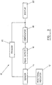
- machine diagnosis apparatus 10 comprising a positional indicator 12 in the form of a laser pointer, a sensor 14, peak detect means 16, a comparator 18, trigger means 20 and a display 22.
- a positional indicator 12 in the form of a laser pointer
- sensor 14 peak detect means 16
- comparator 18 trigger means 20
- display 22 a display 22
- the function of these main parts of apparatus 10 will be described in turn. We consider first the generalities of infra-red emission and the distance of the sensor from the emitter, by reference to Figs 1 and 2.
- the sensor of Fig 3 is adapted to sense infra-red radiation emitted from a defined spot or zone location by the machine under test, for example selected brakes, in turn, of a vehicle braking system.
- the main operating parameters of the sensor are design-determined and set, including distance from the object sensed and the adjusted setting of the means for varying the area from which radiation is received, (to determine D).
- the positional indicator 12 is operatively connected to the sensor to enable visual verification of the zone sensed in terms of its position.
- positional indicator 12 may vary according to requirements. It has been found convenient to employ a laser pointer of the kind which is available as an off-the-shelf device. However, optical or even mechanical devices may be utilised to provide a simple positional relationship between the infra-red sensor and the spot or zone from which it receives I/R energy. The significance of ability to direct the sensor accurately can be appreciated from the fact that in these embodiments it is frequently necessary to direct the sensor at a single wheel-mounting nut and stud assembly. The same need for accuracy of positional alignment arises where it is necessary to obtain temperature samples by use of inspection pit facilities below the level of the vehicle's wheels and chassis. The need to gain access may involve a time delay requiring the application of temperature compensation factors in the thermal comparison step or a repetition of the brake test on the second wheel or axle under conditions identical to the first test.
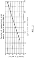
- Fig 2 There is shown in Fig 2 the relationship between the diameter (D) of the measurement area and the sensor to object distance (d). As shown, the size of the zone sensed is unaffected by sensor distance up to approximately 60 centimetres and then increases linearly, as shown.
- the sensor is sensitive to wavelengths between 1 and 14 microns, the exact range of wavelength being determined by the proposed operating environment and function of the device.
- An indium/antimony sensor for example, has a peak detectivity at 5.5 microns and responds to a temperature range of 27 to 1000 degrees celsius.
- Fig 1 shows a typical black body spectrum output for a body at the four temperatures indicated.
- the apparatus 10 includes means for adapting the indicated temperature in accordance with emissivity value of the object under scrutiny, using an emissivity value of from 0.00 to 1.00.
- the infra-red sensor 14 is driven by a voltage supply to produce an analogue voltage signal. This signal is fed to the peak detect circuit 16 which functions to ensure that the maximum signal is indicated. Comparator 18 compares the signal to the previous signal and displays a selected option of the resulting data namely the difference, or both, or the final signals.
- Display 22 is activated by trigger 20 which causes sensor 14 to stop reading.
- Positional indicator 12 (which operates optically or mechanically or electronically) is employed to ensure that sensor 14 is directed onto the required zone of the machine under test. Signal processing, which has been functionally described above, is performed using analogue or digital data.
- Sensor 14 incorporates an emissivity adjustment capability to take account of differences in the emissivity of materials from which temperatures are to be sampled.
- emissivity adjustment capability to take account of differences in the emissivity of materials from which temperatures are to be sampled.
- oxidised steel has an emissivity of 0.80 units
- a thick oil film has an emissivity of 0.83 units
- metallic paint has an emissivity of 0.52 units and chrome a value of 0.08 units.
- Appropriate adjustment to offset emissivity variation factors is needed in order to avoid inappropriate readings.
- the material from which the I/R emission is sampled will be the same for each of a pair of readings, whereby no adjustment is needed because the absolute value of the temperature sampled is of less significance than its relative magnitude as between the two readings.
- the apparatus 10 of Fig 3 is adapted for processing of the data in digital form using an analogue-to-digital convertor 26 (indicated as ADC) which feeds digital data to a processor 28 which is controlled by function keys 30 and is also connected to a recording system 32 and a memory function 34.
- ADC analogue-to-digital convertor
- Fig 4 Among the advantages of the embodiment of Fig 4 is its ability to add processor functions to the output of the apparatus including for example data and time indications, vehicle identification numbers, long time memory recall and integration with pre-stored information.
- infra-red sensing of selected spots or zones in the area of the disc or drum is used to measure the temperature of the disc or drum, or of the surrounding area.
- This temperature data provides an indication of the energy dissipated by the brake, and hence the braking capacity.
- the table below gives an example of a vehicle wheel and disc brake assembly in terms of temperatures generated during use.
- the temperature of the disc is measured, as described previously, by gaining access to the disc by use of inspection pit facilities. Care is taken to ensure that the measurement area is entirely on the disc surface. This is achieved by appropriate alignment of the sensor and control of same by the positional indicator.
- Readings are taken around the circumference of the brake discs to obtain an average value. This lessens the effect of local hot-spots caused by uneven geometry of the braking elements. Readings are taken from the right and left hand side discs of each axle, to determine the degree of imbalance.
- the mathematical expression of the imbalance corresponds to that for side-to-side imbalance with substitution of temperature readings for wheels/axles on the same side of the vehicle as opposed to opposite sides.
- the sensing of the disc temperatures at opposite sides of the axles and on the front and rear axles enables a comparison of the temperature data to identify and diagnose remedial action required, in accordance with the principles of the invention.
- an Agema TPT 50 infra-red spot thermometer was employed as the sensor means, being sensitive to radiation in the wave band 8 to 14 microns, and including an RS 232 interface (communication protocol) to allow transfer of data from the sensor to the data processing apparatus, including a personal computer, for analysis purposes.
- RS 232 interface communication protocol
- a compensation equation is applied utilising an exponential calculated from Newtons' law of cooling, applied to the relevant machine surface.
- the passenger vehicle tests were performed on a SUN VIC 4000 roller tester using passenger vehicles with both disc and drum brakes.
- a constant braking force was applied for a known period of time and then the surface disc temperature was subsequently measured using the infra-red sensor, the maximum temperature being sensed being then used to provide a basis for the imbalance calculation.
- the goods vehicle tests were carried out on an HGV roller test facility of the kind used to test for compliance with legislative requirements.
- the sensor apparatus was provided with a clear view of the target sensed area on the brake.
- a peak algorithm was employed in the sensing system to record only the highest temperature reached during each measurement.
- the angle between the central axis of the sensor and the target was as close to the perpendicular as possible so as to reduce the effect of reflected radiation from other hot sources.
- brake disc temperature was measured directly after braking and from several different points. Where it is desired to monitor wheel nut/stud temperature (meaning the assembly of a wheel-mounting nut and its associated stud) then the thermal changes occur relatively slowly as compared with the adjacent brake disc due to conductivity factors. Where it is desired to monitor nut/stud temperature, the nut temperature should be monitored at intervals for sufficient time until it has reached its maximum value. Existing tests on passenger and heavy goods vehicle wheels show that this could take between 400 and 1000 seconds to occur.
- Test results in the embodiments showed that temperature imbalance correlated well with mechanical brake imbalance.
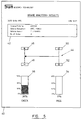
- Fig 5 shows a typical test result obtainable with the apparatus of the invention.
- brake test report sheet 40 sets out vehicle identification data at 42 and a vehicle wheel configuration diagram is provided at 44 with indications provided on the wheels of the test results in terms of the comparability of braking effort provided by the respective brake assemblies of the wheels.
- the vehicle rear wheels 50 and 52 provide braking effort which is substantially balanced, as shown by the balanced diagram 54, which indicates a zero per cent difference in braking effort
- the front wheels 46 and 48 show a 26 per cent braking imbalance in diagram 56, and this is clarified on wheels 46 and 48 by the plus and minus indications provided thereon to indicate which of these provides the higher braking effort.
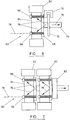
- Figs 6 and 7 show somewhat diagrammatic representations of wheel and brake and stub axle assemblies in an automotive vehicle to which the method and apparatus of the invention is applicable.
- wheel 60 comprises a tyre 62 mounted on a wheel rim and disc assembly 64 secured by threaded studs and nuts, (indicated at 66) to a wheel hub 68 mounted on a stub shaft 70 carrying a brake disc 72, and journalled on the vehicle in the usual way.
- Brake disc 72 has the usual caliper 74 with associated brake pads (not shown).
- a dual wheel assembly 80 is shown, of the kind employed in trucks or heavy goods vehicles. Parts corresponding to those discussed above in relation to Fig 6 are numbered as in Fig 6, for simplicity, and likewise the heat-flow indications 76.
- stub axle 70 is of course longer and, as is usual in heavy goods vehicles, a brake drum 82 is provided with the usual internal shoes.
- the generation of heat corresponds to that of disc 72 and caliper 74, though in this case the heat is generated internally of drum 82 at the friction interface between its inner radial-facing surface and the corresponding faces of the shoes. This heat is nevertheless likewise conducted outwards as indicated at 76 and temperature readings can be taken from nut/stud assemblies 66.
- Fig 8 shows the degree of correlation between temperature readings obtained directly from a brake disc corresponding to disc 72 in Fig 6 and from wheel nut temperatures sensed at nut/stud assembly 66 on the same wheel assembly.
- the disc temperatures are indicated by the group of four plots indicated generally at 90, and the corresponding group of four plots obtained from the nuts 66 are indicated at 92..
- the degree of correlation between these tests is immediately apparent. There is some divergence of the results with increasing time, but the time intervals involved are sufficiently long for this not to raise serious difficulties.
- the absolute values of the temperatures are of less significance than their relative magnitudes.
- the plots shown in Fig 8 indicate that wheel nut temperatures sensed provide a good indication of corresponding brake disc temperatures.
- Fig 9 there is shown a comparison of wheel nut and hub temperatures in an assembly of the kind shown in Figs 7.
- the nut temperatures are sensed at 66 and the wheel hub temperatures are sensed at a suitable location on the main body of the wheel assembly 64.
Landscapes
- Engineering & Computer Science (AREA)
- Physics & Mathematics (AREA)
- General Physics & Mathematics (AREA)
- Transportation (AREA)
- Mechanical Engineering (AREA)
- Braking Arrangements (AREA)
- Diaphragms For Electromechanical Transducers (AREA)
- Analysing Materials By The Use Of Radiation (AREA)
- Investigating Strength Of Materials By Application Of Mechanical Stress (AREA)
- Valves And Accessory Devices For Braking Systems (AREA)
Applications Claiming Priority (2)
| Application Number | Priority Date | Filing Date | Title |
|---|---|---|---|
| GB9503274 | 1995-02-21 | ||
| GBGB9503274.4A GB9503274D0 (en) | 1995-02-21 | 1995-02-21 | Method and apparatus for machine diagnosis |
Publications (3)
| Publication Number | Publication Date |
|---|---|
| EP0729018A2 true EP0729018A2 (fr) | 1996-08-28 |
| EP0729018A3 EP0729018A3 (fr) | 1997-01-29 |
| EP0729018B1 EP0729018B1 (fr) | 2001-07-18 |
Family
ID=10769882
Family Applications (1)
| Application Number | Title | Priority Date | Filing Date |
|---|---|---|---|
| EP96301135A Expired - Lifetime EP0729018B1 (fr) | 1995-02-21 | 1996-02-20 | Méthode et appareil pour tester les freins |
Country Status (5)
| Country | Link |
|---|---|
| US (1) | US5730526A (fr) |
| EP (1) | EP0729018B1 (fr) |
| AT (1) | ATE203325T1 (fr) |
| DE (1) | DE69613870T2 (fr) |
| GB (1) | GB9503274D0 (fr) |
Cited By (6)
| Publication number | Priority date | Publication date | Assignee | Title |
|---|---|---|---|---|
| WO1999004236A1 (fr) * | 1997-07-19 | 1999-01-28 | Snap-On Equipment Limited | Procede et appareil de controle thermique de performances de freinage |
| WO1999008018A1 (fr) * | 1997-08-07 | 1999-02-18 | Meritor Heavy Vehicle Systems, Llc | Procede et appareil de detection d'un dispositif de rattrapage de jeu de freins mal regles |
| AU741091B2 (en) * | 1997-07-31 | 2001-11-22 | Schlumberger Technology B.V. | A method and apparatus for measuring well characteristics and formation properties |
| GB2329943B (en) * | 1997-07-19 | 2002-02-06 | Sun Electric Uk Ltd | Thermal testing method and apparatus |
| US7497305B2 (en) | 2000-08-04 | 2009-03-03 | Meggitt Aerospace Limited | Brake condition monitoring |
| EP1052606B2 (fr) † | 1999-05-14 | 2013-07-17 | TECNOSITAF S.p.A. | Système thermographique pour contrôler et empêcher les incendies dans un véhicule |
Families Citing this family (16)
| Publication number | Priority date | Publication date | Assignee | Title |
|---|---|---|---|---|
| US5833365A (en) * | 1995-03-24 | 1998-11-10 | Interuniversitair Micro-Electronika Centrum Vzw | Method for local temperature sensing for use in performing high resolution in-situ parameter measurements |
| US5942753A (en) * | 1997-03-12 | 1999-08-24 | Remote Sensing Technologies | Infrared remote sensing device and system for checking vehicle brake condition |
| US6311162B1 (en) * | 1998-07-25 | 2001-10-30 | Ernst F. Reichwein | Interactive symptomatic recording system and methods |
| DE19949705A1 (de) * | 1999-10-15 | 2001-05-23 | Bosch Gmbh Robert | Verfahren und Einrichtung zum Prüfen der Bremsanlage eines Fahrzeuges |
| JP2001208860A (ja) * | 1999-12-03 | 2001-08-03 | Novartis Ag | パッケージ中の成形物を検出する方法及び装置 |
| US7001065B2 (en) * | 2003-05-05 | 2006-02-21 | Ray Dishaw | Oilfield thread makeup and breakout verification system and method |
| US7132653B2 (en) * | 2004-01-07 | 2006-11-07 | Robert Carl Faubion | Apparatus for visual comparison of infrared images |
| US7340331B2 (en) * | 2004-08-12 | 2008-03-04 | Snap-On Incorporated | Vehicle data recorder using digital and analog diagnostic data |
| US8985848B2 (en) * | 2006-06-30 | 2015-03-24 | Bdc Capital Inc. | Thermal inspection system |
| US8478480B2 (en) * | 2006-10-27 | 2013-07-02 | International Electronic Machines Corp. | Vehicle evaluation using infrared data |
| AT506109B1 (de) * | 2007-11-20 | 2010-06-15 | Palfinger Systems Gmbh | Verfahren zur untersuchung der oberflächenbeschaffenheit von flächigen strukturen |
| EP2347238B1 (fr) * | 2008-10-22 | 2018-05-16 | International Electronic Machines Corp. | Analyse de véhicules à base d'imagerie thermique |
| EP2459430B1 (fr) * | 2009-07-29 | 2019-11-20 | Wabtec Control Systems Pty Ltd | Procédé pour surveiller l'état de paliers de véhicule ferroviaire |
| GB2509666B (en) | 2011-10-31 | 2017-12-13 | Measurement Ltd | Combination tire temperature, pressure and depth measuring device |
| US10506193B2 (en) | 2016-07-19 | 2019-12-10 | Snap-On Incorporated | Methods and systems for displaying a thermal image and information related to servicing a vehicle |
| US11529979B2 (en) * | 2020-03-10 | 2022-12-20 | Progress Rail Services Corporation | Systems and methods for adjusting train operation |
Family Cites Families (40)
| Publication number | Priority date | Publication date | Assignee | Title |
|---|---|---|---|---|
| US3350702A (en) * | 1965-01-26 | 1967-10-31 | Ruth A Herman | Infrared detection system for fault isolation and failure prediction |
| US3461284A (en) * | 1967-09-05 | 1969-08-12 | Ivan L Joy | Heat detecting system |
| US3686954A (en) * | 1971-04-08 | 1972-08-29 | Allied Power Ind Inc | Automobile air conditioner test and service equipment |
| US4069712A (en) * | 1977-03-25 | 1978-01-24 | United Technologies Corporation | Thermostat setting diagnostics for internal combustion engine |
| US4310003A (en) * | 1978-02-06 | 1982-01-12 | Schlager Kenneth J | Thermographic method of physical examination of patients |
| JPS5853729A (ja) * | 1981-09-25 | 1983-03-30 | Chisso Eng Kk | 管の外周断熱層の性能検査方法 |
| US4584523A (en) * | 1983-10-03 | 1986-04-22 | Rca Corporation | Measurement of the current flow in an electric power transmission line by detection of infrared radiation therefrom |
| DE3502052A1 (de) * | 1985-01-23 | 1986-07-24 | Wabco Westinghouse Fahrzeugbremsen GmbH, 3000 Hannover | Einrichtung zum messen und/oder regeln des verschleisses eines bauteils |
| DE3502050A1 (de) * | 1985-01-23 | 1986-07-24 | Wabco Westinghouse Fahrzeugbremsen GmbH, 3000 Hannover | Einrichtung zum messen und/oder regeln einer bremskraft und/oder eines bremsmomentes |
| US4658936A (en) * | 1985-07-25 | 1987-04-21 | Goodyear Aerospace Corporation | Brake temperature and wear indicator |
| JPS6258893U (fr) * | 1985-09-30 | 1987-04-11 | ||
| JPS62172249A (ja) * | 1986-01-25 | 1987-07-29 | Kajima Corp | 煙突の劣化診断方法及び装置 |
| JPS62200041A (ja) * | 1986-02-28 | 1987-09-03 | Sumitomo Heavy Ind Ltd | 電気制御系の異常検出方法 |
| EP0265538B1 (fr) * | 1986-10-28 | 1990-01-03 | SIGNALTECHNIK GmbH | Dispositif pour la mesure sans contact des températures des freins de voitures de chemin de fer qui passent |
| DE3639664C2 (de) * | 1986-11-20 | 1995-10-19 | Teves Gmbh Alfred | Verfahren und Vorrichtung zur Überwachung des Zustandes oder der Beschaffenheit einer hydraulischen Flüssigkeit |
| JPS63203935A (ja) * | 1987-02-18 | 1988-08-23 | Nissin Kogyo Kk | 車両用ブレ−キにおける制動輪の温度表示装置 |
| US4804237A (en) * | 1987-04-27 | 1989-02-14 | Eaton Corporation | Tractor-trailer brake control system |
| JPS6436564A (en) * | 1987-08-01 | 1989-02-07 | Keio Teito Electric Railway | Wheel temperature detector |
| US4824260A (en) * | 1988-04-13 | 1989-04-25 | Abex Corporation | Brake block temperature and wear measuring device |
| US4854162A (en) * | 1988-06-27 | 1989-08-08 | Ford Motor Company | Method of locating friction generating defects in a multiple bearing assembly |
| NO166424C (no) * | 1989-01-10 | 1991-07-17 | Elkem Technology | Fremgangsmaate for deteksjon av overflatesprekker i metallemner. |
| JPH02200041A (ja) * | 1989-01-30 | 1990-08-08 | Nec Corp | 光受信回路 |
| JPH03182185A (ja) * | 1989-12-11 | 1991-08-08 | Fujitsu Ltd | 赤外線監視システム |
| JP2855734B2 (ja) * | 1989-12-29 | 1999-02-10 | 東洋紡績株式会社 | 熱収縮性フィルム |
| US5032727A (en) * | 1990-09-14 | 1991-07-16 | Digital Equipment Corporation | Product defect detection using thermal ratio analysis |
| US5094544A (en) * | 1990-10-19 | 1992-03-10 | Square D Company | Scanning infrared thermometer with DC offset and emissivity correction |
| DE4035242A1 (de) * | 1990-11-06 | 1992-05-07 | Siemens Ag | Betriebsueberwachung eines rohre aufweisenden kondensators mit messungen an ausgewaehlten rohren |
| US5101106A (en) * | 1991-04-02 | 1992-03-31 | Digital Equipment Corporation | Resonant technique and apparatus for thermal capacitor screening |
| GB9113966D0 (en) * | 1991-06-28 | 1991-08-14 | Ferodo Ltd | Apparatus for temperature detection |
| US5246291A (en) * | 1992-06-01 | 1993-09-21 | Motorola, Inc. | Bond inspection technique for a semiconductor chip |
| US5372221A (en) * | 1992-07-20 | 1994-12-13 | Otis Elevator Company | Active brake sensor |
| US5292195A (en) * | 1992-09-09 | 1994-03-08 | Martin Marietta Corporation | Thermographic evaluation technique |
| US5302940A (en) * | 1992-10-05 | 1994-04-12 | Chen Chi Shan | Motor vehicle brake detector |
| US5331311A (en) * | 1992-12-09 | 1994-07-19 | Servo Corporation Of America | Railroad wheel temperature sensor with infrared array |
| US5419415A (en) * | 1992-12-21 | 1995-05-30 | Inventio Ag | Apparatus for monitoring elevator brakes |
| AT400989B (de) * | 1992-12-21 | 1996-05-28 | Vae Ag | Einrichtung zum erkennen unzulässig erwärmter bauteile bzw. stellen an bewegten objekten |
| DE4319996A1 (de) * | 1993-06-17 | 1994-12-22 | Gerd R Dipl Ing Wetzler | Verfahren zur berührungsfreien Erfassung der Oberflächentemperatur rotierender Scheiben |
| US5381669A (en) * | 1993-07-21 | 1995-01-17 | Copeland Corporation | Overcharge-undercharge diagnostic system for air conditioner controller |
| US5440890A (en) * | 1993-12-10 | 1995-08-15 | Copeland Corporation | Blocked fan detection system for heat pump |
| US5463222A (en) * | 1994-01-24 | 1995-10-31 | Colorado Seminary | Thermal imaging system for internal combustion engines |
-
1995
- 1995-02-21 GB GBGB9503274.4A patent/GB9503274D0/en active Pending
-
1996
- 1996-02-20 EP EP96301135A patent/EP0729018B1/fr not_active Expired - Lifetime
- 1996-02-20 US US08/602,513 patent/US5730526A/en not_active Expired - Lifetime
- 1996-02-20 AT AT96301135T patent/ATE203325T1/de not_active IP Right Cessation
- 1996-02-20 DE DE69613870T patent/DE69613870T2/de not_active Expired - Fee Related
Cited By (11)
| Publication number | Priority date | Publication date | Assignee | Title |
|---|---|---|---|---|
| WO1999004236A1 (fr) * | 1997-07-19 | 1999-01-28 | Snap-On Equipment Limited | Procede et appareil de controle thermique de performances de freinage |
| AU741273B2 (en) * | 1997-07-19 | 2001-11-29 | Snap-On Equipment Limited | Method and apparatus for thermal testing of brake performance |
| GB2329943B (en) * | 1997-07-19 | 2002-02-06 | Sun Electric Uk Ltd | Thermal testing method and apparatus |
| US6442457B1 (en) * | 1997-07-19 | 2002-08-27 | Snap-On Equipment Limited | Method and apparatus for thermal testing of brake performance |
| AU741091B2 (en) * | 1997-07-31 | 2001-11-22 | Schlumberger Technology B.V. | A method and apparatus for measuring well characteristics and formation properties |
| WO1999008018A1 (fr) * | 1997-08-07 | 1999-02-18 | Meritor Heavy Vehicle Systems, Llc | Procede et appareil de detection d'un dispositif de rattrapage de jeu de freins mal regles |
| EP1052606B2 (fr) † | 1999-05-14 | 2013-07-17 | TECNOSITAF S.p.A. | Système thermographique pour contrôler et empêcher les incendies dans un véhicule |
| US7497305B2 (en) | 2000-08-04 | 2009-03-03 | Meggitt Aerospace Limited | Brake condition monitoring |
| US7506941B2 (en) | 2000-08-04 | 2009-03-24 | Meggitt Aerospace Limited | Brake condition monitoring |
| US7901014B2 (en) | 2000-08-04 | 2011-03-08 | Meggitt Aerospace Limited | Brake condition monitoring |
| US8152246B2 (en) * | 2000-08-04 | 2012-04-10 | Meggitt Aerospace Limited | Brake condition monitoring |
Also Published As
| Publication number | Publication date |
|---|---|
| DE69613870T2 (de) | 2001-10-31 |
| ATE203325T1 (de) | 2001-08-15 |
| EP0729018A3 (fr) | 1997-01-29 |
| EP0729018B1 (fr) | 2001-07-18 |
| US5730526A (en) | 1998-03-24 |
| GB9503274D0 (en) | 1995-04-12 |
| DE69613870D1 (de) | 2001-08-23 |
Similar Documents
| Publication | Publication Date | Title |
|---|---|---|
| US5730526A (en) | Method and apparatus for machine diagnosis | |
| Thevenet et al. | Measurements of brake disc surface temperature and emissivity by two-color pyrometry | |
| US6883962B2 (en) | Tire wear forecasting method and apparatus | |
| MX2007006513A (es) | Rueda de tren con deteccion de temperatura. | |
| Kasem et al. | Relationships between surface thermal gradients and disc distortion during stop-braking with high energy dissipation | |
| US3807226A (en) | Non-linear amplification technique for improving signal to noise contrast | |
| US4673298A (en) | Tire temperature measurement apparatus | |
| Kožuch et al. | Dynamic and stationary testing of vehicle braking systems | |
| Segal | Diagnostic method for vehicle brakes | |
| AU741273B2 (en) | Method and apparatus for thermal testing of brake performance | |
| Wetenkamp et al. | Hot spot heating by composition shoes | |
| US3982429A (en) | Computer type brake analyzer | |
| US3974688A (en) | Computer type brake analyzer | |
| Litos et al. | A measuring system for experimental research on the thermomechanical coupling of disc brakes | |
| Sivakov et al. | Improving machine assemblies’ diagnosis with the use of thermal imaging camera | |
| Jones et al. | Novel Contact-Free Brake Tester for Roadside Inspection of Vehicles | |
| JPH0422445B2 (fr) | ||
| US3965732A (en) | Computer type brake analyzer | |
| US20260103178A1 (en) | Vehicle Brake Disc Temperature Monitoring Method and Apparatus | |
| Dubensky | Experimental techniques for rotor performance measurements | |
| Cañás et al. | Badanie termowizyjne hamulca tarczowego spalinowego zespołu trakcyjnego w warunkach poligonowych | |
| Cañás et al. | Thermal imaging test of the disk brake of a diesel multiple unit in field conditions | |
| Wilburn | A temperature study of pneumatic tires during highway operation | |
| Cantoni et al. | Tire and brake interaction-a new test rig to study wheel locking | |
| Wetenkamp et al. | The influence of brake shoes on the temperatures of wheels in railroad service |
Legal Events
| Date | Code | Title | Description |
|---|---|---|---|
| PUAI | Public reference made under article 153(3) epc to a published international application that has entered the european phase |
Free format text: ORIGINAL CODE: 0009012 |
|
| AK | Designated contracting states |
Kind code of ref document: A2 Designated state(s): AT CH DE FR GB IE LI |
|
| PUAL | Search report despatched |
Free format text: ORIGINAL CODE: 0009013 |
|
| 17P | Request for examination filed |
Effective date: 19961024 |
|
| AK | Designated contracting states |
Kind code of ref document: A3 Designated state(s): AT CH DE FR GB IE LI |
|
| 17Q | First examination report despatched |
Effective date: 19990322 |
|
| RAP1 | Party data changed (applicant data changed or rights of an application transferred) |
Owner name: SNAP-ON EQUIPMENT LIMITED |
|
| RAP3 | Party data changed (applicant data changed or rights of an application transferred) |
Owner name: SNAP-ON EQUIPMENT LIMITED |
|
| GRAG | Despatch of communication of intention to grant |
Free format text: ORIGINAL CODE: EPIDOS AGRA |
|
| GRAG | Despatch of communication of intention to grant |
Free format text: ORIGINAL CODE: EPIDOS AGRA |
|
| GRAH | Despatch of communication of intention to grant a patent |
Free format text: ORIGINAL CODE: EPIDOS IGRA |
|
| GRAH | Despatch of communication of intention to grant a patent |
Free format text: ORIGINAL CODE: EPIDOS IGRA |
|
| GRAH | Despatch of communication of intention to grant a patent |
Free format text: ORIGINAL CODE: EPIDOS IGRA |
|
| GRAA | (expected) grant |
Free format text: ORIGINAL CODE: 0009210 |
|
| AK | Designated contracting states |
Kind code of ref document: B1 Designated state(s): AT CH DE FR GB IE LI |
|
| REF | Corresponds to: |
Ref document number: 203325 Country of ref document: AT Date of ref document: 20010815 Kind code of ref document: T |
|
| REG | Reference to a national code |
Ref country code: CH Ref legal event code: EP |
|
| REG | Reference to a national code |
Ref country code: CH Ref legal event code: NV Representative=s name: BRAUN & PARTNER PATENT-, MARKEN-, RECHTSANWAELTE |
|
| REG | Reference to a national code |
Ref country code: IE Ref legal event code: FG4D |
|
| REF | Corresponds to: |
Ref document number: 69613870 Country of ref document: DE Date of ref document: 20010823 |
|
| ET | Fr: translation filed | ||
| REG | Reference to a national code |
Ref country code: GB Ref legal event code: IF02 |
|
| PLBE | No opposition filed within time limit |
Free format text: ORIGINAL CODE: 0009261 |
|
| STAA | Information on the status of an ep patent application or granted ep patent |
Free format text: STATUS: NO OPPOSITION FILED WITHIN TIME LIMIT |
|
| 26N | No opposition filed | ||
| REG | Reference to a national code |
Ref country code: GB Ref legal event code: 732E |
|
| REG | Reference to a national code |
Ref country code: CH Ref legal event code: PUE Owner name: SNAP-ON INCORPORATED Free format text: SNAP-ON EQUIPMENT LIMITED#UNIT12 HORSLEYS FIELDS#KING'S LYNN NORFOLK PE30 5DD (GB) -TRANSFER TO- SNAP-ON INCORPORATED#10801 CORPORATE DRIVE#PLEASANT PRAIRIE, WISCONSIN 53158-1603 (US) |
|
| REG | Reference to a national code |
Ref country code: CH Ref legal event code: NV Representative=s name: BRAUN & PARTNER PATENT-, MARKEN-, RECHTSANWAELTE |
|
| REG | Reference to a national code |
Ref country code: FR Ref legal event code: TP |
|
| PGFP | Annual fee paid to national office [announced via postgrant information from national office to epo] |
Ref country code: AT Payment date: 20070201 Year of fee payment: 12 |
|
| PGFP | Annual fee paid to national office [announced via postgrant information from national office to epo] |
Ref country code: GB Payment date: 20070223 Year of fee payment: 12 |
|
| PGFP | Annual fee paid to national office [announced via postgrant information from national office to epo] |
Ref country code: IE Payment date: 20070227 Year of fee payment: 12 Ref country code: CH Payment date: 20070227 Year of fee payment: 12 |
|
| PGFP | Annual fee paid to national office [announced via postgrant information from national office to epo] |
Ref country code: DE Payment date: 20070330 Year of fee payment: 12 |
|
| PGFP | Annual fee paid to national office [announced via postgrant information from national office to epo] |
Ref country code: FR Payment date: 20070221 Year of fee payment: 12 |
|
| REG | Reference to a national code |
Ref country code: CH Ref legal event code: PL |
|
| GBPC | Gb: european patent ceased through non-payment of renewal fee |
Effective date: 20080220 |
|
| PG25 | Lapsed in a contracting state [announced via postgrant information from national office to epo] |
Ref country code: LI Free format text: LAPSE BECAUSE OF NON-PAYMENT OF DUE FEES Effective date: 20080229 Ref country code: CH Free format text: LAPSE BECAUSE OF NON-PAYMENT OF DUE FEES Effective date: 20080229 |
|
| REG | Reference to a national code |
Ref country code: IE Ref legal event code: MM4A |
|
| PG25 | Lapsed in a contracting state [announced via postgrant information from national office to epo] |
Ref country code: AT Free format text: LAPSE BECAUSE OF NON-PAYMENT OF DUE FEES Effective date: 20080220 |
|
| REG | Reference to a national code |
Ref country code: FR Ref legal event code: ST Effective date: 20081031 |
|
| PG25 | Lapsed in a contracting state [announced via postgrant information from national office to epo] |
Ref country code: IE Free format text: LAPSE BECAUSE OF NON-PAYMENT OF DUE FEES Effective date: 20080220 Ref country code: DE Free format text: LAPSE BECAUSE OF NON-PAYMENT OF DUE FEES Effective date: 20080902 |
|
| PG25 | Lapsed in a contracting state [announced via postgrant information from national office to epo] |
Ref country code: FR Free format text: LAPSE BECAUSE OF NON-PAYMENT OF DUE FEES Effective date: 20080229 |
|
| PG25 | Lapsed in a contracting state [announced via postgrant information from national office to epo] |
Ref country code: GB Free format text: LAPSE BECAUSE OF NON-PAYMENT OF DUE FEES Effective date: 20080220 |