EP0729255A2 - Verfahren zum automatischen Anpassen von Parametern einer Schnittstelle - Google Patents
Verfahren zum automatischen Anpassen von Parametern einer Schnittstelle Download PDFInfo
- Publication number
- EP0729255A2 EP0729255A2 EP96400294A EP96400294A EP0729255A2 EP 0729255 A2 EP0729255 A2 EP 0729255A2 EP 96400294 A EP96400294 A EP 96400294A EP 96400294 A EP96400294 A EP 96400294A EP 0729255 A2 EP0729255 A2 EP 0729255A2
- Authority
- EP
- European Patent Office
- Prior art keywords
- functions
- membership
- bit
- interface
- transmission
- Prior art date
- Legal status (The legal status is an assumption and is not a legal conclusion. Google has not performed a legal analysis and makes no representation as to the accuracy of the status listed.)
- Granted
Links
- 238000000034 method Methods 0.000 title claims abstract description 17
- 230000006978 adaptation Effects 0.000 title description 3
- 230000006870 function Effects 0.000 claims abstract description 60
- 230000005540 biological transmission Effects 0.000 claims abstract description 31
- 230000008054 signal transmission Effects 0.000 claims 1
- 238000005259 measurement Methods 0.000 description 11
- 238000012545 processing Methods 0.000 description 5
- 238000012423 maintenance Methods 0.000 description 3
- 230000000630 rising effect Effects 0.000 description 3
- 238000012935 Averaging Methods 0.000 description 2
- 238000013459 approach Methods 0.000 description 2
- 238000004891 communication Methods 0.000 description 2
- 238000004519 manufacturing process Methods 0.000 description 2
- 238000012546 transfer Methods 0.000 description 2
- RYGMFSIKBFXOCR-UHFFFAOYSA-N Copper Chemical compound [Cu] RYGMFSIKBFXOCR-UHFFFAOYSA-N 0.000 description 1
- 230000001174 ascending effect Effects 0.000 description 1
- 238000006243 chemical reaction Methods 0.000 description 1
- 230000000295 complement effect Effects 0.000 description 1
- 230000003247 decreasing effect Effects 0.000 description 1
- 230000002950 deficient Effects 0.000 description 1
- 230000001934 delay Effects 0.000 description 1
- 238000001514 detection method Methods 0.000 description 1
- 239000000463 material Substances 0.000 description 1
- 238000004377 microelectronic Methods 0.000 description 1
- 210000000056 organ Anatomy 0.000 description 1
- 230000002093 peripheral effect Effects 0.000 description 1
- 239000010453 quartz Substances 0.000 description 1
- 230000000717 retained effect Effects 0.000 description 1
- VYPSYNLAJGMNEJ-UHFFFAOYSA-N silicon dioxide Inorganic materials O=[Si]=O VYPSYNLAJGMNEJ-UHFFFAOYSA-N 0.000 description 1
- 230000007704 transition Effects 0.000 description 1
- 230000001960 triggered effect Effects 0.000 description 1
Images


Classifications
-
- H—ELECTRICITY
- H04—ELECTRIC COMMUNICATION TECHNIQUE
- H04L—TRANSMISSION OF DIGITAL INFORMATION, e.g. TELEGRAPHIC COMMUNICATION
- H04L9/00—Cryptographic mechanisms or cryptographic arrangements for secret or secure communications; Network security protocols
- H04L9/40—Network security protocols
Definitions
- the present invention relates to a method for automatically adapting the parameters of an interface. It can be used in particular in the field of data processing, for the connection between them of computers, microcomputers or peripherals, in the field of home automation for the use in buildings known as intelligent, as well as in the automotive field.
- a message coded in ASCII protocol consists of a first bit called start, data including a parity bit and, at the end, a bit called stop.
- the different messages are sent one after the other in the same order.
- the information Upon receipt, the information must be decapsulated in this order. This means that the start bit and stop bit must be recognized, the data extracted and checked according to the value of the parity bit.
- the nature of the start and stop bit, the number of data bits, the nature of the parity and the bit rate of the different bits are all parameters that differentiate the protocols.
- the transmitter and the receiver In order to be able to exchange information and understand each other, the transmitter and the receiver must therefore be configured so that they can accomplish this recognition and processing.
- These configurations generally involve human intervention. Indeed, these configurations can be controlled by a battery of small switches or switches that can be operated manually. These switches and switches are generally located behind the devices and sometimes it is even necessary to dismantle their rear face. Very often, it is necessary to refer to the instructions for use and / or the instructions for use to carry out the configuration. This configuration is also not so easy, because the switches and switches are often difficult to access.
- This mode of exchange has another drawback.
- you connect to another type of device you have to repeat the same operations. This is the case for example for printers, fax machines, telephones, measurements taken by RS232 link, emulators, etc.
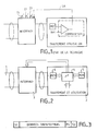
- Figure 1 shows another type of circuit state of the art interface.
- the interface circuit shown comprises manual switch switches I1, I2, I3 as well as an automatic selection link SA connecting a symbolic circuit for comparing the message transmitted with a reference REF to an input for controlling the interface.
- control signals, transmitted by the SA link, of these interface circuits are different. Therefore, it is necessary to multiply the number of control buses for their connection with the microprocessor or microcontroller of the device which processes and uses the received messages.
- the data bus is not a problem.
- the order of the data bits is reversed.
- the weight of the strongest bit is on the left and sometimes the weight of the strongest bit is on the right.
- either the interface circuit performs the inversion function.
- the micro-controller or processor of the device to achieve this type of inversion.
- part of the resources of the microprocessor or controller is used to perform this secondary task, to the detriment of its efficiency.
- VAN is a French protocol
- CAM and ABB are German protocols
- J1850 protocol is from the United States.
- Each equipment manufacturer produces specific interface circuits for his own needs. Here we see four information recognition interface circuits appear.
- a motorist who buys a car of brand Y is obliged for the maintenance of his car to bring it to the dealers of the brand Y. Otherwise, no maintenance operation can be carried out. For example, through its diagnostic device, another dealer cannot detect the defective organ because its device only understands and communicates with one type of protocol which is not the one chosen by the Y brand. .
- the device For the diagnostic device to understand one or the other protocol, the device must be equipped with two interface circuits capable of processing this information and of understanding the message and of transferring this data received to the microprocessor or micro-controller. We can continue to cite examples of this type.
- the idea of the invention is based firstly on the other type of interface circuit shown symbolically in Figure 1, and secondly on fuzzy logic.
- the idea is to treat all the protocols (for example (VAN, CAM ABB, J1850) by the same circuit, with reasoning in human natural language which simplifies at the same time the complexity of the circuit of comparison of figure 1.
- the most advantageous consequence of the invention is to reduce the cost of the material because the number of connectors as well as the number of interface circuits are then reduced.
- a single interface circuit for car applications based on fuzzy logic, will be able to deal with the four types of protocols mentioned above and in particular to adapt the transmission speed. Indeed the speed of information transmission can vary from 75 bits per second to 1 Mbits per second.
- the invention can be applicable to all types of transmission media: radio frequency, infrared, coaxial cable, twisted pair, carrier current, etc.
- FIG. 2 shows a device which can be used to implement the adaptation method of the invention.
- a transmission link 1 is connected to an apparatus 2 for processing and using the signals transmitted via an interface 3.
- the apparatus 2 comprises a fuzzy microprocessor ⁇ F, referenced 4 , usable for implementing selection rules as well as for storing membership functions, in particular in speed.
- These membership functions are, in accordance with FIGS. 5a to 5b, pairs of data addresses and data value, such that the address represents the value of a variable, and such that the value of the data represents a degree (normally understood between 0 and 1) assigned for each value of the variable.
- Rules are a set of combinations of conditions of the SI-THEN type. To simplify, initially concerning the automobile field, we will only study the adaptation to the transfer speed.
- the fuzzy microprocessor is for example a microprocessor of the WARP 1.1 or WARP 2 type. manufactured by SGS THOMSON MICROELECTRONICS.
- the apparatus 2 conventionally comprises a MES measurement circuit 6 for measuring, on the signal received, physically, the characteristics of this signal which reveal its transmission protocol.
- a measurement circuit is moreover already existing in the state of the art.
- a wired home automation interface circuit was provided, calling in particular on a measurement of the characteristics of the signals received, on a conversion into binary of the analog signals measured, and in the production, with a microprocessor of the comparison circuit allowing the remote control of the interface.
- the programming of this microprocessor itself is specific for carrying out this comparison circuit and cannot be easily transposed to multiple situations.
- Figure 3 shows a typical example of a message transmitted over a link.
- a message includes at the start a piece of information, known as the start bit St.
- the start bit St In the ASCII protocol, it is a first bit at 1 whose transition of the rising edge is detected.
- the start bit is detected by the presence of a rising edge on a data bus when the clock, transmitted by one of the wires of a control, is at a high state.
- Other start bit patterns are possible, it is even possible to have a grouping of bits indicating the start of the message.
- the data is then coded with variable numbers of bits: the most frequently used bit lengths are 7.8, 9, 10 and 11 bits.
- a Pa bit known as parity is sent. Either this parity bit is a complement to the content of the message to make it even or odd according to the chosen protocol, or this parity bit is a bit always at zero or always at one according to the chosen protocol.
- an end bit is transmitted, called the stop bit Sp.
- the stop bit can be recognized by its shape, it lasts for example longer than a normal bit, or by its format: it can be itself made up of several bits.
- FIG. 4 shows connected to link 1 a detailed example of a measurement circuit 6.
- This measurement circuit will be used to essentially measure the transfer speed, and moreover the bit format, the value of the parity bit, the value of the stop bit.
- the measurement circuit 6 includes for this purpose a flip-flop D7 receiving as input the signals transmitted by one of the wires of the data bus (in the case of parallel transmission), or by the data transmission wire (in the case of a serial transmission ).
- Flip-flop D7 transmits the rising edge of the signal it receives, its output Q.
- the output Q of flip-flop 7 is connected to the input of an AND gate 8 which also receives the transmitted signal. During the first bit received, the start bit, the AND gate 8 outputs a state 1.
- An output of a clock 9 and the output of AND gate 8 are connected to the input of a second AND gate 10 which therefore outputs a number of pulses depending on the duration of the high slots of the input signal.
- This number of pulses is counted in a counter 11.
- the content of the counter 11 is transmitted to the fuzzy logic microprocessor 4. It serves as an address to represent the bit duration and to deduce therefrom a degree of belonging of the duration measured to a speed membership function.
- This speed membership function is itself implemented in the set of rules stored in memory 5 to determine by a command C intended for the interface how it must be configured.
- the fuzzy microprocessor being a very fast microprocessor (with an internal clock at 50Mhz for example) we can consider that at the transmission speeds mentioned the configuration of the interface as a function of order C is then immediate.
- D 12 flip-flop For the measurement of the other parameters of the received protocol, another example D 12 flip-flop is used in the example shown. This is triggered by a falling edge of the input signal, by connecting the control input of this D12 flip-flop. to the input connection via an inverter 13.
- the output Q of the flip-flop 12 is itself connected as an input to an AND gate 14 which also receives the signal from the clock 9 on another input.
- the output of AND gate 14 is connected to an input of another counter 15 which counts the bits of the message.
- the output of the counter 15 is connected to a decoder 16 which uses the counting result of the counter 15 by decoding to know the nature of the bits and the format of the message.
- the counter 15 counts a certain number of clock pulses 9 which, divided by the first number of clock pulses delivered by the counter 11, gives the number of bits to zero. Then the counter 15 again counts the duration of the one-bit bits of the message. It also appears that we can also gradually, by averaging it, approach the measurement of the bit duration more closely and deduce the speed more precisely, in particular if this must change during a transmission.
- two monostables 17 and 18 are used, connected respectively between the reset input of flip-flop 7 and the output of gate 14 and between the input connection of the received signal. and the reset input of flip-flop 12.
- the commands C transmitted to a microprocessor 19 of the device allow the latter, in particular if it is of the type described in the French patent application cited above, to adapt its various circuits to the protocol thus recognized.
- control signals will essentially comprise a so-called STROBE signal making it possible to inform the microprocessor 19 which manages the interface that the data received is available in accordance with the recognized type of coding and transmission.
- the other signal is an interrupt signal, IRQ. It informs this microprocessor 19 that the decoding of the word, whether it is 8, 9, 10 or 11 bits, is carried out.
- the microprocessor 19 sends to the fuzzy microprocessor 4 an acknowledgment signal ACQ to inform it that the information has been taken into account. Rather than to have a separate clock 9, it is preferable to produce a clock signal from a quartz 20 attached to the microprocessor 19.
- the microprocessor 19 also receives, in particular if it is produced in an integrated circuit at the same time as the interface, the signals available on the link 1. In a preferred variant, the microprocessor 4 and the microprocessor 19 are produced on the same circuit integrated.
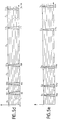
- FIG. 5a shows, with regard to the transmission speed detection, the description of the membership functions stored in the memory 5.
- two axes have been presented symbolically: the time axis and the axis of membership degrees.
- the time axis On the time axis, the different possible values of the bit durations corresponding to the top slots of the transmitted bits have been shown.
- the curve V1 shows that a degree 1 is assigned to any value of the duration of the bit between 50 microseconds and 60 microseconds. This corresponds for example to the normalized limits for bit duration tolerance, around 52 microseconds for transmission at 19,200 bits per second.
- the curve V1 comprises ascending and descending ramps between, respectively 30 microseconds and 40 microseconds and 60 microseconds and 70 microseconds to assign an increasing, or decreasing, degree of belonging. linearly between zero and one if the measured value is outside 40-60.
- the signal measured with the counter 11 delivers information corresponding to 52 microseconds, it will be said that the degree of belonging to the function V1 for the measured value is one. If the measured signal is worth 35 microseconds, we will say that the degree of membership for the function V1 is 0.5.
- bit duration value In V2, V3, V4, V5, etc., nominal values of bit duration have been shown for transmission speeds at 9600, 4800, 2400, 1200, etc., bits per second.
- membership functions We have also included membership functions called X1, X2 etc ... corresponding to greater speeds of V1, or intermediate between the speeds Vi and Vi + 1.
- a bit duration value equal to 52 microseconds will be interpreted as a degree of belonging to the function V1 equal to 1 and a degree of belonging to all the other functions equal to zero.
- FIG. 5b shows under the same conditions the membership functions in number of bits of the message. Normally the number of bits in the message is an integer. However, as indicated above the counter 15 counts bits of the clock 9 and not the bits actually transmitted in the message. Indeed, this is not really possible since the message can contain bits at zero which themselves would not be accountable since the signal would not change state. It is therefore possible that the number of clock bits counted, multiplied by the period of the clock 9 and divided by the bit duration measured by the counter 11 is not exactly an integer. For example, it is possible that the delays involved by the different scales or the different doors cause a loss of counting accuracy. This is not annoying by retaining membership functions, such as that shown in FIG.
- membership functions N1 to N4 are here represented separately, it would however be possible, to take account of poor reception conditions, to tilt the ramps of these membership functions more, so that the functions are no longer separated. So, rather than having a membership degree to all membership functions equal to zero, a bit number value of 8.5 could be assigned a membership degree of 0.25 for the function N1, 0.25 for the N2 function and 0 for the others. This allows, in application of the fuzzy logic rules to remove an ambiguity which is otherwise unacceptable in the case of circuits of the specific type of the state of the art.
- FIG. 5c shows, along an abscissa axis, parity values and an ordinate axis of the degrees of belonging to corresponding functions.
- These membership functions are essentially usable for ASCII type formats.
- the membership function P1 measures the fact that the seventh bit of 8 is equal to one or zero.
- the P2 function measures the fact that the eighth bit of 9 is equal to 1 or zero and so on for the P3 and P4 functions.
- the parity is continuously measured.
- the parity bit is the one preceding the stop bit. Once the latter is recognized, we know the format of the message, the value of the parity bit and the value of the data. We can then determine if the parity of the message is even or odd. For the following message we do the same.
- FIG. 5d shows, in the same way as for FIG. 5a, the taking into account by functions SP1, SP2, SP3 and so on, the duration of the stop bit and the degree of belonging to the various functions allocated.
- the duration of the stop bit provides information on the type of protocol used.
- Figure 5e shows the system output variables by membership functions D1 to D5 when it comes to processing only the speed.
- the result membership functions can be directly interpreted as orders that can be transmitted on the control C bus.
- the function D1 equal to 1 is for example the sign that the speed of 19200 bits per second has been retained.
- the membership functions in result necessarily have steep sides. Indeed, it is a question of giving orders, these cannot be given in half.
- the meaning of the first line is that if the degree of belonging to the function V1 (19200) is equal to 1, if the value of the variable N is equal to N1 (the word received is an 8-bit word), if the value parity P is not equal to 1, and if the value of the stop bit St conforms to the transmission speed, then the output variable D is equal to the output D1 (the word received is at the speed of 19200, the parity is zero and the word is 8 bits).
- a decoder actually contained in the microprocessor 4 produces the signal C from this output D1.
- the word received also conforms to the ASCII standard, the speed is 19,200, the parity is 1 and the word is 8 bits.
- the speed is 9600
- the parity is one
- the words are 8, 9 and 10 bits respectively.
- the output is zero, this means that the message is not recognized and does not conform to one of the expected standards. He is not saved in memory 5: it is not possible to configure the interface of microprocessor 19. We can see that we can easily update the interface if new protocols appear: just increase the set of rules . It may be necessary to create other intermediate membership functions.
- the combination is a combination of product type or minimum type known in the field of fuzzy logic.
Landscapes
- Engineering & Computer Science (AREA)
- Computer Security & Cryptography (AREA)
- Computer Networks & Wireless Communication (AREA)
- Signal Processing (AREA)
- Communication Control (AREA)
- Computer And Data Communications (AREA)
Applications Claiming Priority (2)
| Application Number | Priority Date | Filing Date | Title |
|---|---|---|---|
| FR9501998 | 1995-02-21 | ||
| FR9501998A FR2730835B1 (fr) | 1995-02-21 | 1995-02-21 | Procede d'adaptation automatique des parametres d'une interface |
Publications (3)
| Publication Number | Publication Date |
|---|---|
| EP0729255A2 true EP0729255A2 (de) | 1996-08-28 |
| EP0729255A3 EP0729255A3 (de) | 2005-06-15 |
| EP0729255B1 EP0729255B1 (de) | 2007-04-11 |
Family
ID=9476367
Family Applications (1)
| Application Number | Title | Priority Date | Filing Date |
|---|---|---|---|
| EP96400294A Expired - Lifetime EP0729255B1 (de) | 1995-02-21 | 1996-02-13 | Verfahren zum automatischen Anpassen von Parametern einer Schnittstelle |
Country Status (5)
| Country | Link |
|---|---|
| US (1) | US5809234A (de) |
| EP (1) | EP0729255B1 (de) |
| JP (1) | JP2689402B2 (de) |
| DE (1) | DE69637013T2 (de) |
| FR (1) | FR2730835B1 (de) |
Cited By (1)
| Publication number | Priority date | Publication date | Assignee | Title |
|---|---|---|---|---|
| EP0859312A1 (de) * | 1997-02-18 | 1998-08-19 | STMicroelectronics S.A. | Verfahren zur Benutzung eines Fuzzy-Logic-Prozessors in einem Netzwerk und dafür geeigneter Fuzzy-Logic-Prozessor |
Families Citing this family (11)
| Publication number | Priority date | Publication date | Assignee | Title |
|---|---|---|---|---|
| US6125446A (en) * | 1997-08-29 | 2000-09-26 | Compaq Computer Corporation | Computer architecture with automatic disabling of hardware/software features using satellite positioning data |
| US6804595B1 (en) * | 1999-09-03 | 2004-10-12 | Siemens Vdo Automotive Corporation | Controller for occupant restraint system |
| TWI233141B (en) * | 2001-12-26 | 2005-05-21 | Nat Science Council | Method of equipment management |
| JP2005182624A (ja) * | 2003-12-22 | 2005-07-07 | Sharp Corp | 情報処理装置、情報処理システム、通信速度設定方法、通信速度設定プログラム、およびそのプログラムを記録した記録媒体 |
| US7493482B2 (en) * | 2005-12-21 | 2009-02-17 | Caterpillar Inc. | Self-configurable information management system |
| CA2776890C (en) * | 2009-10-06 | 2018-04-10 | Rfid Mexico S.A. De C.V. | Geographical localization system |
| US20120303533A1 (en) | 2011-05-26 | 2012-11-29 | Michael Collins Pinkus | System and method for securing, distributing and enforcing for-hire vehicle operating parameters |
| US20130060721A1 (en) | 2011-09-02 | 2013-03-07 | Frias Transportation Infrastructure, Llc | Systems and methods for pairing of for-hire vehicle meters and medallions |
| US9037852B2 (en) | 2011-09-02 | 2015-05-19 | Ivsc Ip Llc | System and method for independent control of for-hire vehicles |
| US20130253999A1 (en) | 2012-03-22 | 2013-09-26 | Frias Transportation Infrastructure Llc | Transaction and communication system and method for vendors and promoters |
| DE102013220922A1 (de) * | 2013-10-16 | 2015-04-16 | Zf Friedrichshafen Ag | Telematiksystem, Verfahren und Telematikfahrzeugeinheit |
Family Cites Families (17)
| Publication number | Priority date | Publication date | Assignee | Title |
|---|---|---|---|---|
| US4751634A (en) * | 1985-06-14 | 1988-06-14 | International Business Machines Corporation | Multiple port communications adapter apparatus |
| US5206812A (en) * | 1987-04-03 | 1993-04-27 | Alcatel Business Systems Limited | Franking machine |
| US4972470A (en) * | 1987-08-06 | 1990-11-20 | Steven Farago | Programmable connector |
| FR2619234B1 (fr) * | 1987-08-07 | 1991-04-19 | Ricard Claude | Procedes et dispositifs adaptateurs pour introduire des donnees dans des taximetres electroniques a partir d'un ordinateur central relie temporairement a un terminal local |
| JP3067023B2 (ja) * | 1988-09-29 | 2000-07-17 | オムロン株式会社 | ファジィデータ送信方法、ファジィデータ送信装置、ファジィデータ受信方法、ファジィデータ受信装置およびファジィデータ通信装置 |
| JPH04502991A (ja) * | 1988-11-14 | 1992-05-28 | データーポイント・コーポレーション | 動的に選択可能な多重操作性を備えたローカル・エリア・ネットワーク |
| JP2802088B2 (ja) * | 1989-02-06 | 1998-09-21 | 株式会社日立製作所 | プロトコル選択切替方法 |
| US5200992A (en) * | 1989-06-30 | 1993-04-06 | Canon Kabushiki Kaisha | Communication apparatus having changeable communication procedure signals |
| US5457784A (en) * | 1992-03-05 | 1995-10-10 | Metacomp, Inc. | Interfacing system using an auto-adapting multi-ported control module between an i/o port and a plurality of peripheral adaptors via bus extending cables |
| EP0596648A1 (de) * | 1992-11-02 | 1994-05-11 | National Semiconductor Corporation | Erkennung du Fähigkeiten eines Netzendpunkts |
| FR2699351B1 (fr) * | 1992-12-14 | 1995-01-13 | Sgs Thomson Microelectronics | Dispositif de connexion d'un appareil à un canal de transmission. |
| US5490134A (en) * | 1993-06-29 | 1996-02-06 | Southern California Edison Company | Versatile communications controller |
| EP0636967A1 (de) * | 1993-07-29 | 1995-02-01 | STMicroelectronics S.r.l. | Verfahren und Vorrichtung für die Speicherung von Zugehörigkeitsfunktionen |
| WO1995008886A1 (en) * | 1993-09-20 | 1995-03-30 | Cabletron Systems, Inc. | Communications network management system and method, using fuzzy logic |
| US5635940A (en) * | 1994-02-02 | 1997-06-03 | Hickman; Paul L. | Communication configurator and method for implementing same |
| US5646865A (en) * | 1994-10-27 | 1997-07-08 | General Motors Corporation | Automotive diagnostic communications |
| US5649001A (en) * | 1995-03-24 | 1997-07-15 | U.S. Robotics Mobile Communications Corp. | Method and apparatus for adapting a communication interface device to multiple networks |
-
1995
- 1995-02-21 FR FR9501998A patent/FR2730835B1/fr not_active Expired - Fee Related
-
1996
- 1996-02-13 EP EP96400294A patent/EP0729255B1/de not_active Expired - Lifetime
- 1996-02-13 DE DE69637013T patent/DE69637013T2/de not_active Expired - Lifetime
- 1996-02-20 US US08/604,103 patent/US5809234A/en not_active Expired - Lifetime
- 1996-02-21 JP JP8058472A patent/JP2689402B2/ja not_active Expired - Fee Related
Cited By (3)
| Publication number | Priority date | Publication date | Assignee | Title |
|---|---|---|---|---|
| EP0859312A1 (de) * | 1997-02-18 | 1998-08-19 | STMicroelectronics S.A. | Verfahren zur Benutzung eines Fuzzy-Logic-Prozessors in einem Netzwerk und dafür geeigneter Fuzzy-Logic-Prozessor |
| FR2759799A1 (fr) * | 1997-02-18 | 1998-08-21 | Sgs Thomson Microelectronics | Procede d'utilisation en reseau d'un processeur de logique floue, et processeur de logique floue utilisable en reseau |
| US6263324B1 (en) | 1997-02-18 | 2001-07-17 | Sgs-Thomson Microelectronics S.A. | Method and apparatus for the use of a fuzzy logic processor in a network |
Also Published As
| Publication number | Publication date |
|---|---|
| DE69637013D1 (de) | 2007-05-24 |
| FR2730835A1 (fr) | 1996-08-23 |
| US5809234A (en) | 1998-09-15 |
| EP0729255B1 (de) | 2007-04-11 |
| FR2730835B1 (fr) | 1997-03-14 |
| JPH08256193A (ja) | 1996-10-01 |
| DE69637013T2 (de) | 2007-12-13 |
| JP2689402B2 (ja) | 1997-12-10 |
| EP0729255A3 (de) | 2005-06-15 |
Similar Documents
| Publication | Publication Date | Title |
|---|---|---|
| EP0729255B1 (de) | Verfahren zum automatischen Anpassen von Parametern einer Schnittstelle | |
| EP0046831B1 (de) | System für die wiederholte Übertragung fehlerhaft empfangener numerierter Rahmen in einem Datenübertragungssystem | |
| EP0026135B1 (de) | Verfahren zum Prüfen einer Digitaldatenübertragungsleitung zwischen zwei Modems und Vorrichtung zur Durchführung dieses Verfahrens | |
| EP0272969B1 (de) | Verfahren und programmierbare Vorrichtung zur Umkodierung von Zeichenketten | |
| FR2578070A1 (fr) | Procede pour faire fonctionner une installation de traitement de donnees pour des vehicules a moteur | |
| EP0702481B1 (de) | Detektor für Trägerverlust in einem Faksimile-Modem | |
| FR2988949A1 (fr) | Dispositif de communication et procede de programmation ou de correction d'erreur d'un ou plusieurs participants du dispositif de communication | |
| EP0166838B1 (de) | Verfahren und Anordnung zur Detektion einer besonderen Bitkonfiguration in einem seriellen Bitstrom | |
| FR2676131A1 (fr) | Systeme de communication. | |
| FR2837296A1 (fr) | Dispositif et procede d'acquisition de mesures a l'aide d'un bus de communication numerique, utilises notamment lors des essais d'un aeronef | |
| EP0702469A1 (de) | Erkennungsgerät für FSK Trainingsfolgen | |
| FR2553950A1 (fr) | Dispositif de transmission bidirectionnelle de donnees digitalisees par liaison electrique bifilaire entre un controleur central et des unites peripheriques dispersees | |
| FR2653620A1 (fr) | Carte a circuit integre sans contact. | |
| FR2520956A1 (fr) | Systeme de transmission asynchrone, notamment pour systeme de videotex interactif | |
| FR2651345A1 (fr) | Systeme d'allocation a orientation prioritaire d'un bus. | |
| FR2860891A1 (fr) | Carte a circuit integre apte a transmettre automatiquement une information d'octet nul sans intervention de l'unite centrale | |
| EP1503559A1 (de) | Verfahren zur automatischen Übertragungsprotokollerkennung für ein tragbares Objekt von der Art einer Karte oder eines Schlüssels mit integrierter Schaltung (smart card, smart key) | |
| EP0013853A1 (de) | Vorrichtung zur Datenübertragung zwischen einer zentralen Einheit eines Datenprozessors und einer peripheren Einheit | |
| FR2661269A1 (fr) | Cartes a circuits integres. | |
| FR2788184A1 (fr) | Methode, dispositif de detection de l'appel d'un telephone et modem comportant un tel dispositif | |
| EP0441707B1 (de) | Koppler für Serienbus | |
| CH645223A5 (fr) | Dispositif de controle des communications dans un reseau de transmission en duplex. | |
| EP0549992B1 (de) | Datenringnetz und Verfahren zur Übertragung von Daten über das Netz | |
| FR3093198A1 (fr) | Transmission de données liées sur bus I2C | |
| FR2674395A1 (fr) | Procede de transmission de donnes numeriques emises sous forme de trames de signaux differentiels. |
Legal Events
| Date | Code | Title | Description |
|---|---|---|---|
| PUAI | Public reference made under article 153(3) epc to a published international application that has entered the european phase |
Free format text: ORIGINAL CODE: 0009012 |
|
| AK | Designated contracting states |
Kind code of ref document: A2 Designated state(s): DE FR GB IT |
|
| 17P | Request for examination filed |
Effective date: 19970205 |
|
| RAP3 | Party data changed (applicant data changed or rights of an application transferred) |
Owner name: STMICROELECTRONICS S.A. |
|
| RAP1 | Party data changed (applicant data changed or rights of an application transferred) |
Owner name: STMICROELECTRONICS S.A. |
|
| PUAL | Search report despatched |
Free format text: ORIGINAL CODE: 0009013 |
|
| AK | Designated contracting states |
Kind code of ref document: A3 Designated state(s): DE FR GB IT |
|
| GRAP | Despatch of communication of intention to grant a patent |
Free format text: ORIGINAL CODE: EPIDOSNIGR1 |
|
| GRAS | Grant fee paid |
Free format text: ORIGINAL CODE: EPIDOSNIGR3 |
|
| GRAA | (expected) grant |
Free format text: ORIGINAL CODE: 0009210 |
|
| AK | Designated contracting states |
Kind code of ref document: B1 Designated state(s): DE FR GB IT |
|
| REG | Reference to a national code |
Ref country code: GB Ref legal event code: FG4D Free format text: NOT ENGLISH |
|
| REF | Corresponds to: |
Ref document number: 69637013 Country of ref document: DE Date of ref document: 20070524 Kind code of ref document: P |
|
| GBV | Gb: ep patent (uk) treated as always having been void in accordance with gb section 77(7)/1977 [no translation filed] |
Effective date: 20070411 |
|
| REG | Reference to a national code |
Ref country code: GB Ref legal event code: 710B Free format text: EXTENSION APPLICATION: APPLICATION FOR EXTENSION OF THE PERIOD(S) PRESCRIBED BY RULE(S) SCHEDULE 4 PARA 2 FILED ON 20071129 |
|
| PLBE | No opposition filed within time limit |
Free format text: ORIGINAL CODE: 0009261 |
|
| STAA | Information on the status of an ep patent application or granted ep patent |
Free format text: STATUS: NO OPPOSITION FILED WITHIN TIME LIMIT |
|
| GBT | Gb: translation of ep patent filed (gb section 77(6)(a)/1977) |
Effective date: 20080130 |
|
| GBV | Gb: ep patent (uk) treated as always having been void in accordance with gb section 77(7)/1977 [no translation filed] |
Effective date: 20070411 |
|
| 26N | No opposition filed |
Effective date: 20080114 |
|
| PG25 | Lapsed in a contracting state [announced via postgrant information from national office to epo] |
Ref country code: GB Free format text: LAPSE BECAUSE OF FAILURE TO SUBMIT A TRANSLATION OF THE DESCRIPTION OR TO PAY THE FEE WITHIN THE PRESCRIBED TIME-LIMIT Effective date: 20070411 |
|
| PGFP | Annual fee paid to national office [announced via postgrant information from national office to epo] |
Ref country code: IT Payment date: 20080213 Year of fee payment: 13 Ref country code: GB Payment date: 20080129 Year of fee payment: 13 |
|
| PGRI | Patent reinstated in contracting state [announced from national office to epo] |
Ref country code: GB Effective date: 20080124 |
|
| PGFP | Annual fee paid to national office [announced via postgrant information from national office to epo] |
Ref country code: FR Payment date: 20080228 Year of fee payment: 13 |
|
| GBPC | Gb: european patent ceased through non-payment of renewal fee |
Effective date: 20090213 |
|
| REG | Reference to a national code |
Ref country code: FR Ref legal event code: ST Effective date: 20091030 |
|
| PG25 | Lapsed in a contracting state [announced via postgrant information from national office to epo] |
Ref country code: GB Free format text: LAPSE BECAUSE OF NON-PAYMENT OF DUE FEES Effective date: 20090213 Ref country code: FR Free format text: LAPSE BECAUSE OF NON-PAYMENT OF DUE FEES Effective date: 20090302 |
|
| PG25 | Lapsed in a contracting state [announced via postgrant information from national office to epo] |
Ref country code: IT Free format text: LAPSE BECAUSE OF NON-PAYMENT OF DUE FEES Effective date: 20090213 |
|
| PGFP | Annual fee paid to national office [announced via postgrant information from national office to epo] |
Ref country code: DE Payment date: 20110207 Year of fee payment: 16 |
|
| REG | Reference to a national code |
Ref country code: DE Ref legal event code: R119 Ref document number: 69637013 Country of ref document: DE Effective date: 20120901 |
|
| PG25 | Lapsed in a contracting state [announced via postgrant information from national office to epo] |
Ref country code: DE Free format text: LAPSE BECAUSE OF NON-PAYMENT OF DUE FEES Effective date: 20120901 |