EP0729542B1 - Spanneinrichtung für die gewichtsausgleichs-torsionsfedereinrichtung eines torblattes - Google Patents
Spanneinrichtung für die gewichtsausgleichs-torsionsfedereinrichtung eines torblattes Download PDFInfo
- Publication number
- EP0729542B1 EP0729542B1 EP95900626A EP95900626A EP0729542B1 EP 0729542 B1 EP0729542 B1 EP 0729542B1 EP 95900626 A EP95900626 A EP 95900626A EP 95900626 A EP95900626 A EP 95900626A EP 0729542 B1 EP0729542 B1 EP 0729542B1
- Authority
- EP
- European Patent Office
- Prior art keywords
- shaft
- chuck
- tensioning
- worm wheel
- tensioning device
- Prior art date
- Legal status (The legal status is an assumption and is not a legal conclusion. Google has not performed a legal analysis and makes no representation as to the accuracy of the status listed.)
- Expired - Lifetime
Links
- 238000011067 equilibration Methods 0.000 title 1
- 230000033001 locomotion Effects 0.000 claims abstract description 15
- 238000006243 chemical reaction Methods 0.000 claims description 5
- 239000011324 bead Substances 0.000 claims description 4
- 238000010276 construction Methods 0.000 claims 1
- 238000000034 method Methods 0.000 description 10
- 230000005540 biological transmission Effects 0.000 description 4
- 230000015572 biosynthetic process Effects 0.000 description 4
- 238000005096 rolling process Methods 0.000 description 3
- 238000005553 drilling Methods 0.000 description 2
- 238000003780 insertion Methods 0.000 description 2
- 230000037431 insertion Effects 0.000 description 2
- 238000009434 installation Methods 0.000 description 2
- 241000237858 Gastropoda Species 0.000 description 1
- 238000005266 casting Methods 0.000 description 1
- 230000008878 coupling Effects 0.000 description 1
- 238000010168 coupling process Methods 0.000 description 1
- 238000005859 coupling reaction Methods 0.000 description 1
- 238000005520 cutting process Methods 0.000 description 1
- 238000006073 displacement reaction Methods 0.000 description 1
- 238000005516 engineering process Methods 0.000 description 1
- 238000005304 joining Methods 0.000 description 1
- 238000005192 partition Methods 0.000 description 1
- 238000009420 retrofitting Methods 0.000 description 1
- 238000000926 separation method Methods 0.000 description 1
- 238000004804 winding Methods 0.000 description 1
Images
Classifications
-
- E—FIXED CONSTRUCTIONS
- E06—DOORS, WINDOWS, SHUTTERS, OR ROLLER BLINDS IN GENERAL; LADDERS
- E06B—FIXED OR MOVABLE CLOSURES FOR OPENINGS IN BUILDINGS, VEHICLES, FENCES OR LIKE ENCLOSURES IN GENERAL, e.g. DOORS, WINDOWS, BLINDS, GATES
- E06B9/00—Screening or protective devices for wall or similar openings, with or without operating or securing mechanisms; Closures of similar construction
- E06B9/56—Operating, guiding or securing devices or arrangements for roll-type closures; Spring drums; Tape drums; Counterweighting arrangements therefor
- E06B9/60—Spring drums operated only by closure members
-
- E—FIXED CONSTRUCTIONS
- E05—LOCKS; KEYS; WINDOW OR DOOR FITTINGS; SAFES
- E05D—HINGES OR SUSPENSION DEVICES FOR DOORS, WINDOWS OR WINGS
- E05D13/00—Accessories for sliding or lifting wings, e.g. pulleys, safety catches
- E05D13/10—Counterbalance devices
- E05D13/12—Counterbalance devices with springs
- E05D13/1253—Counterbalance devices with springs with canted-coil torsion springs
- E05D13/1261—Counterbalance devices with springs with canted-coil torsion springs specially adapted for overhead wings
-
- E—FIXED CONSTRUCTIONS
- E05—LOCKS; KEYS; WINDOW OR DOOR FITTINGS; SAFES
- E05Y—INDEXING SCHEME ASSOCIATED WITH SUBCLASSES E05D AND E05F, RELATING TO CONSTRUCTION ELEMENTS, ELECTRIC CONTROL, POWER SUPPLY, POWER SIGNAL OR TRANSMISSION, USER INTERFACES, MOUNTING OR COUPLING, DETAILS, ACCESSORIES, AUXILIARY OPERATIONS NOT OTHERWISE PROVIDED FOR, APPLICATION THEREOF
- E05Y2201/00—Constructional elements; Accessories therefor
- E05Y2201/40—Motors; Magnets; Springs; Weights; Accessories therefor
- E05Y2201/499—Spring tensioners; Tension sensors
-
- E—FIXED CONSTRUCTIONS
- E05—LOCKS; KEYS; WINDOW OR DOOR FITTINGS; SAFES
- E05Y—INDEXING SCHEME ASSOCIATED WITH SUBCLASSES E05D AND E05F, RELATING TO CONSTRUCTION ELEMENTS, ELECTRIC CONTROL, POWER SUPPLY, POWER SIGNAL OR TRANSMISSION, USER INTERFACES, MOUNTING OR COUPLING, DETAILS, ACCESSORIES, AUXILIARY OPERATIONS NOT OTHERWISE PROVIDED FOR, APPLICATION THEREOF
- E05Y2800/00—Details, accessories and auxiliary operations not otherwise provided for
- E05Y2800/69—Permanence of use
- E05Y2800/692—Temporary use, e.g. removable tools
-
- E—FIXED CONSTRUCTIONS
- E05—LOCKS; KEYS; WINDOW OR DOOR FITTINGS; SAFES
- E05Y—INDEXING SCHEME ASSOCIATED WITH SUBCLASSES E05D AND E05F, RELATING TO CONSTRUCTION ELEMENTS, ELECTRIC CONTROL, POWER SUPPLY, POWER SIGNAL OR TRANSMISSION, USER INTERFACES, MOUNTING OR COUPLING, DETAILS, ACCESSORIES, AUXILIARY OPERATIONS NOT OTHERWISE PROVIDED FOR, APPLICATION THEREOF
- E05Y2900/00—Application of doors, windows, wings or fittings thereof
-
- E—FIXED CONSTRUCTIONS
- E05—LOCKS; KEYS; WINDOW OR DOOR FITTINGS; SAFES
- E05Y—INDEXING SCHEME ASSOCIATED WITH SUBCLASSES E05D AND E05F, RELATING TO CONSTRUCTION ELEMENTS, ELECTRIC CONTROL, POWER SUPPLY, POWER SIGNAL OR TRANSMISSION, USER INTERFACES, MOUNTING OR COUPLING, DETAILS, ACCESSORIES, AUXILIARY OPERATIONS NOT OTHERWISE PROVIDED FOR, APPLICATION THEREOF
- E05Y2900/00—Application of doors, windows, wings or fittings thereof
- E05Y2900/10—Application of doors, windows, wings or fittings thereof for buildings or parts thereof
- E05Y2900/106—Application of doors, windows, wings or fittings thereof for buildings or parts thereof for garages
Definitions
- the invention relates to a tensioning device for at least one torsion spring device, which is assigned to a wave, the latter with a door leaf - preferably a one- or multi-part gate that can be moved overhead, for example Ceiling sectional gates - connected in terms of gears, and its movement process implemented in a rotational movement, the Torsion spring device an end, preferably the associated Shaft bearing facing, held stationary against rotation and other end is connected to a chuck that around the Rotatable shaft and - after tensioning the spring by turning the chuck - which chuck with the coaxial can be locked against rotation
- Worm gear of a worm gear which is preferably self-locking is provided, the worm for a gear connection to the worm wheel in a for the purpose of torsion spring tension on the shaft or the Chuck mounted on the chuck housing and attached to a conventional, motorized - especially electric motor-driven tools with rotary Drive, such as a hand drill, can be connected, which clamping housing for the Is placed circumferentially on the shaft
- Tensioning torsion springs for balancing the weight in particular Sectional gates are usually made by hand, for example by the usual one Formation of a following the intake cone of the opposite the torsion spring device receiving shaft movable clamping part or Chuck with four radial holes evenly distributed over the circumference, in which you can use tension levers.
- This work must be carried out on site with pre-assembled Spring wave are made, so usually in proportion high altitude.
- the forces to be applied are towards the end of the clamping process extraordinarily high, so that taking into account the location of the fitter appearing on a ladder and there are considerable accidents Forces must be applied.
- a tensioning device with the features mentioned above is already from the US 3,921,761 known. Instead of a device with which the chuck in more or less difficult handling in any case with regard to the to be applied Clamping force is only operated by hand, this allows known Formation of the clamping device with a worm gear, the output side Coupling to the chuck of a torsion spring to be tensioned and its drive-side connection option to a motor-driven Tools such as hand drills are only used to operate this tool Required actuation with only one hand and without the torque for tensioning the spring only by manual actuation have to.
- the invention has for its object a tensioning device of the beginning to provide the type mentioned, the tensioning of the torsion spring device for the fitter less dangerous and with less manual operation allowed.
- the worm gear is self-locking trained, i.e. when decoupling the hand tools from the gear the tensioned spring does not restrict the gearbox as far as the drive member move. This also simplifies handling for the clamping process or an interruption of the tensioning process, intended or by Slipping of the hand tools does not lead to a return of the spring tension.
- the transmission gear consists of one Worm gear with a to the chuck or the taper of the for tensioning the spring end to be rotated relative to the shaft connected worm wheel and a worm engaging in it as Drive member, which is held rotatably in a clamping housing for the clamping process can be connected to the hand tools at one of its two shaft ends.
- the clamping housing is part of the clamping device, which is only for the Clamping process can be placed on the shaft or the chuck such that the geared connection between the drive member and driven member and is ensured.
- the clamping housing is at least circumferentially formed in two parts, preferably in the form of one in the case of touchdown on the shaft this U-shaped enclosing main part, through the leg ends Bores are guided, which in the mounting state a locking pin record that the shaft introduced into the U-shaped main part in this Position is locked in such a way that the gear connection between the Clamping housing and the chuck, in particular between the screw as the drive member and the worm wheel as an output member is ensured.
- After removal of the locking pin passing through the coaxial bores can be the Main part of the clamping housing and thus this in its entirety with separation Remove the gear connection from the shaft or chuck.
- the clamping housing with a transversely in the mounting state Longitudinal direction of the shaft extending boom provided, in particular with its end facing away from the clamping housing at the lintel area with the door leaf attacks the door opening to be closed, in particular by means of a Rolling body arranged in this cantilever end region, preferably spherical, because the torsion spring shaft in the course of tensioning in the axial direction the shaft undergoes an extension of the clamping housing and thus the boom by moving the shaft in the longitudinal direction.
- the boom is preferably variable in length to adapt to spatially different conditions, in particular simply by means of supports positioned differently on the clamping housing.
- the worm wheel of the transmission gear is flanged to the chuck.
- too Worm wheel formed in one piece with the chuck.
- This latter version is primarily for original equipment of a wave of the in question kind suitable.
- the chuck and the output member then preferably form a casting.
- an existing chuck subsequently in the invention Way to be provided with a tensioning device this can be done by utilizing the radial holes provided in the chuck for the
- tensioning levers is particularly preferred due to a two-part, i.e.
- a connecting body in realize axial longitudinal median plane, forming a connecting body, the one with the protruding perpendicular to the central plane, in the assembled state in pins engaging diametrically opposite radial bores is provided and after joining the two half-shells the output member of the gear, in particular the worm wheel.
- the clamping housing or connection body With multi-part training of the clamping housing or connection body must be due to the uniform Ensure the circumferential course of the worm wheel be worn that its configuration also taking into account the Rotation relative to the shaft is ensured, for example, what one achieved by distance-securing adapter sleeves, which are in aligned holes in the intervene several, in particular two, parts to be connected and by Bolts of corresponding screw connections are penetrated.
- the tensioning housing together with the, in particular, approximately quarter-circle-shaped, hollow-throat gear formation of the worm wheel on the shaft applied state a the gear engagement between worm and worm wheel securing lock against axial relative movements, in particular by a provided on the clamping housing projection on a shoulder or in a Groove that engages in the quarter-circle toothing of the worm wheel axially facing area of the worm wheel or chuck unit and worm wheel or the connecting body.
- the at least one torsion spring device mentioned here which is used for weight compensation a door leaf with a vertical component is used, is in conventionally by a correspondingly encompassing the shaft with its coils strong torsion spring formed. There are of these torsion springs on a wave two or more. These individual torsion springs can also by bundles of parallel, weaker torsion springs be formed, which are coupled via a planetary gear. Depending on Installation conditions and design can actuate the drive element, in particular a worm with shaft sections provided on both end faces, be desirable from both axial directions of the drive member, which is why a corresponding accessibility on both sides for the connection of the hand tools is preferred.
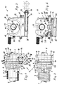
- the figures all show a section of a shaft 1, as is known in the art Way for the weight compensation and / or the drive of door leaves with vertical Motion component is used, i.e. for single-leaf overhead doors, Lifting gates and in particular overhead or sectional gates; basically Such a shaft can also be used in the area of a winding shaft for roller doors.
- cable drums are on both ends of the shaft provided, the end facing away from these windable and unwound ropes are attached to the door leaf and thus create a gear connection the movement of the door leaf in an accompanying rotational movement of the shaft implement; these facilities are generally known.
- this high-speed transmission 8 is a self-locking, single-stage worm gear, so that the drive member of the Worm 10 and the output member corresponds to the worm wheel 9, the latter arranged coaxially to the chuck and connected to it so that it cannot rotate is.
- worm 10 is a motor-driven Hand tools, for example electric hand drill optionally from one of the two shaft ends 25 of the screw 10 which has a torsion-proof manner Rotation shaft 24, connectable, so that with the relatively high output speed the drilling machine a relatively slow clamping rotation of the spring can be reached without the handling of the drilling machine causing problems and without the repercussions from the tensioned spring from the drill hold hand when driving from the drill interrupted on the snail.
- motor-driven Hand tools for example electric hand drill optionally from one of the two shaft ends 25 of the screw 10 which has a torsion-proof manner Rotation shaft 24, connectable, so that with the relatively high output speed the drilling machine a relatively slow clamping rotation of the spring can be reached without the handling of the drilling machine causing problems and without the repercussions from the tensioned spring from the drill hold hand when driving from the drill interrupted on the snail.
- the chuck 5 is included the worm wheel arranged on the side axially facing away from the torsion spring 2 9 formed in one piece, namely under a molded between them Groove 19.
- the worm wheel 9 has an approximately quarter circle Toothing parallel in the area axially facing away from chuck 5 to the axis of the shaft 1 and other end directed approximately radially outwards is formed on an annular bead 18 between the and the chuck 5 the circumferential groove 19 is formed.
- the clamping housing 11 has a main part 12 and a locking pin 13. Of the Main part is U-shaped in the axial direction of shaft 1 and houses it the worm 10 in its web. In the state applied to the shaft 1 this is included in the base area between the legs 15 and the web and is overlapped by the locking pin 13, which is used for this purpose through holes arranged in alignment in the free end regions of the legs 17 is performed.
- the shaft is enclosed with such little play that the worm 10 in terms of gear technology in the groove-shaped toothing of the worm wheel 9 intervenes properly.
- This radial alignment of the worm 10 is supplemented by an axial position lock, which is given in that the Clamping housing 11 with a projection 20 in the groove 19 between the chuck 5th and annular bead 18 engages, as can be seen in FIGS. 1 and 2.
- the rotation shaft 24, which receives the worm 10 in a rotationally fixed manner or in one piece therewith is located in the area of the web 14 of the clamping housing 11, namely by two ball bearings 26 against axial and radial movements - bearing collars 27 and mounting parts 28 held.
- the terminal training 25 for the optional connection to a hand drill from one of the two shaft ends.
- connection designs are designed like a screw head, which correspond in size to the screw heads of the locking screws 22, with which the chuck 5 is rotatably connected to the shaft 1 can be.
- These locking screws 22 are facing away from her head End provided with cutting edges that are also under the maximum tension of the spring ensure this torsional strength.
- the locking screws are preferably located in the area the hub of the chuck 5 between the radial bores 6.
- the torsion spring With this rolling body lies the Boom, for example, at the lintel of the door opening during the tensioning process the torsion spring and rolls on it.
- the blind bores are made in the web 14 from both directions, and in different depths, so that from both sides the possibility of different depth insertion of the boom 32 results, whereby a corresponding "change in length" of the boom, i.e. a different one Distance between web 14 and roller 33 can adjust.
- One deep blind bore 31 is axially a correspondingly short blind bore 29 ' across from. This applies accordingly to the other two holes provided.
- the locking pin 13 has one end provided a handpiece and secured against loss at 23 on the clamping housing fixed.
- the leg ends receiving the aligned bores 17 are provided with bevels 16 on the outside.
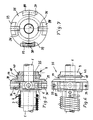
- the further exemplary embodiment according to FIGS. 5 and 7 works with the same Clamping housing 11, as in connection with the first embodiment described according to Figures 1 to 4.
- the second embodiment is characterized by a for retrofitting an existing chuck 5 with radial bores 6 in that the worm wheel 9 having Connection body 35 is provided separately in two parts in the central axis plane is.
- This connector body 35 engages after application to the shaft, that is Merging its two parts, with pin 36, which are perpendicular to Partition plane extend radially inwards in two diametrically opposite one another Radial bores of the chuck 5 a.
- the two halves of the connector body 35 are joined by means of two screw connections 37, which each pass through a sleeve 38 which in correspondingly aligned holes of the two parts of the connecting body 35 in the respective screw area are used. Due to the adapter sleeves 38, the alignment and spacing of the two parts determined exactly, so that the formation of the worm gear 9 is technically flawlessly manufactured. Both the pins 36 as well as the adapter sleeves 38 and thus screw connections 37 are each in axially projecting regions 39 of the connecting body 35. Also in this The exemplary embodiment is the toothing 40 of the worm wheel 9 in the form of a groove as stated in the first embodiment, which is why the one to be used in each case Clamping housing 11 can match.
Landscapes
- Engineering & Computer Science (AREA)
- Structural Engineering (AREA)
- Architecture (AREA)
- Civil Engineering (AREA)
- Mechanical Engineering (AREA)
- Gear Transmission (AREA)
- Springs (AREA)
- Vehicle Body Suspensions (AREA)
- Devices For Conveying Motion By Means Of Endless Flexible Members (AREA)
- Operating, Guiding And Securing Of Roll- Type Closing Members (AREA)
- Registering, Tensioning, Guiding Webs, And Rollers Therefor (AREA)
- Elevator Door Apparatuses (AREA)
- Closing And Opening Devices For Wings, And Checks For Wings (AREA)
- Automatic Cycles, And Cycles In General (AREA)
Applications Claiming Priority (5)
| Application Number | Priority Date | Filing Date | Title |
|---|---|---|---|
| DE4339202 | 1993-11-16 | ||
| DE4339202 | 1993-11-16 | ||
| DE4341309A DE4341309C1 (de) | 1993-11-16 | 1993-12-03 | Spanneinrichtung für die Gewichtsausgleichs-Torsionsfeder eines Torblattes |
| DE4341309 | 1993-12-03 | ||
| PCT/DE1994/001345 WO1995014150A1 (de) | 1993-11-16 | 1994-11-15 | Spanneinrichtung für die gewichtsausgleichs-torsionsfedereinrichtung eines torblattes |
Publications (2)
| Publication Number | Publication Date |
|---|---|
| EP0729542A1 EP0729542A1 (de) | 1996-09-04 |
| EP0729542B1 true EP0729542B1 (de) | 1998-10-21 |
Family
ID=25931287
Family Applications (1)
| Application Number | Title | Priority Date | Filing Date |
|---|---|---|---|
| EP95900626A Expired - Lifetime EP0729542B1 (de) | 1993-11-16 | 1994-11-15 | Spanneinrichtung für die gewichtsausgleichs-torsionsfedereinrichtung eines torblattes |
Country Status (7)
| Country | Link |
|---|---|
| EP (1) | EP0729542B1 (da) |
| AT (1) | ATE172515T1 (da) |
| DK (1) | DK0729542T3 (da) |
| ES (1) | ES2122507T3 (da) |
| FI (1) | FI104912B (da) |
| NO (1) | NO309160B1 (da) |
| WO (1) | WO1995014150A1 (da) |
Family Cites Families (2)
| Publication number | Priority date | Publication date | Assignee | Title |
|---|---|---|---|---|
| US3921761A (en) * | 1974-04-12 | 1975-11-25 | Univ Iowa State Res Found Inc | Method and means of winding torsion spring |
| US4981165A (en) * | 1989-04-11 | 1991-01-01 | Millco Products, Inc. | Spring adjustment device for overhead doors |
-
1994
- 1994-11-15 WO PCT/DE1994/001345 patent/WO1995014150A1/de not_active Ceased
- 1994-11-15 DK DK95900626T patent/DK0729542T3/da active
- 1994-11-15 EP EP95900626A patent/EP0729542B1/de not_active Expired - Lifetime
- 1994-11-15 ES ES95900626T patent/ES2122507T3/es not_active Expired - Lifetime
- 1994-11-15 AT AT95900626T patent/ATE172515T1/de not_active IP Right Cessation
-
1996
- 1996-05-15 FI FI962082A patent/FI104912B/fi active
- 1996-05-15 NO NO961985A patent/NO309160B1/no not_active IP Right Cessation
Also Published As
| Publication number | Publication date |
|---|---|
| ES2122507T3 (es) | 1998-12-16 |
| FI962082L (fi) | 1996-07-15 |
| FI962082A0 (fi) | 1996-05-15 |
| WO1995014150A1 (de) | 1995-05-26 |
| EP0729542A1 (de) | 1996-09-04 |
| FI104912B (fi) | 2000-04-28 |
| NO961985D0 (no) | 1996-05-15 |
| ATE172515T1 (de) | 1998-11-15 |
| NO309160B1 (no) | 2000-12-18 |
| NO961985L (no) | 1996-07-09 |
| DK0729542T3 (da) | 1999-06-28 |
Similar Documents
| Publication | Publication Date | Title |
|---|---|---|
| DE3617217C2 (da) | ||
| DE2758874A1 (de) | Verbesserungen an mit drahtzug arbeitenden fensterhebern, insbesondere fuer kraftfahrzeuge | |
| EP3568264B1 (de) | Spannvorrichtung zum spannen einer schraubenfeder | |
| DE2511081A1 (de) | Schlitz- oder stemm-maschine | |
| EP1426538B1 (de) | Wellentorantriebsvorrichtung, und damit versehenes Tor | |
| DE4341309C1 (de) | Spanneinrichtung für die Gewichtsausgleichs-Torsionsfeder eines Torblattes | |
| DE3141332C2 (de) | Vorrichtung zum Zusammensetzen zweier ineinanderschiebbarer Teile, von denen eines wenigstens einen radial gerichteten Vorsprung aufweist | |
| EP3461594B1 (de) | Getriebeanordnung für eine angetriebene werkzeugmaschine | |
| EP0729542B1 (de) | Spanneinrichtung für die gewichtsausgleichs-torsionsfedereinrichtung eines torblattes | |
| DE3619756C2 (da) | ||
| DE3608988A1 (de) | Vorrichtung zur handbetaetigung einer elektromotorisch antreibbaren wickelwelle z.b. eines rolladens | |
| EP0649492B1 (de) | Motorische antriebseinrichtung für ein torblatt | |
| EP1216335A1 (de) | Zwischengetriebe für fenster-oder türbeschlag | |
| EP0766794B1 (de) | Kupplung | |
| EP0075749A1 (de) | Zweiachsiger elektrischer Kompaktantrieb, insbesondere Stellantrieb | |
| DE9318535U1 (de) | Spanneinrichtung für die Gewichtsausgleichs-Torsionsfedereinrichtung eines Torblattes | |
| DE19938707A1 (de) | Verschraubungswerkzeug mit einem Winkelkopf für Flachabtriebe | |
| DE102012224524B4 (de) | Kopplungsvorrichtung für eine Antriebsvorrichtung sowie Antriebseinrichtung | |
| EP4063606B1 (de) | Getriebe mit freilauf | |
| DE69814079T2 (de) | Befestigungsvorrichtung | |
| DE4414421A1 (de) | Einrichtung zum Spannen einer Torsionsfeder | |
| DE202005007605U1 (de) | Tor mit Wellentorantrieb | |
| EP3943226A1 (de) | Bohrmaschine | |
| DE3616731C2 (da) | ||
| DE3824949A1 (de) | Getriebe fuer sektional- oder rolltore |
Legal Events
| Date | Code | Title | Description |
|---|---|---|---|
| PUAI | Public reference made under article 153(3) epc to a published international application that has entered the european phase |
Free format text: ORIGINAL CODE: 0009012 |
|
| 17P | Request for examination filed |
Effective date: 19960610 |
|
| AK | Designated contracting states |
Kind code of ref document: A1 Designated state(s): AT BE CH DE DK ES FR GB GR IT LI NL SE |
|
| RBV | Designated contracting states (corrected) |
Designated state(s): AT BE CH DE DK ES FR GB GR IT LI NL SE |
|
| GRAG | Despatch of communication of intention to grant |
Free format text: ORIGINAL CODE: EPIDOS AGRA |
|
| 17Q | First examination report despatched |
Effective date: 19980213 |
|
| GRAG | Despatch of communication of intention to grant |
Free format text: ORIGINAL CODE: EPIDOS AGRA |
|
| GRAH | Despatch of communication of intention to grant a patent |
Free format text: ORIGINAL CODE: EPIDOS IGRA |
|
| GRAH | Despatch of communication of intention to grant a patent |
Free format text: ORIGINAL CODE: EPIDOS IGRA |
|
| GRAA | (expected) grant |
Free format text: ORIGINAL CODE: 0009210 |
|
| AK | Designated contracting states |
Kind code of ref document: B1 Designated state(s): AT BE CH DE DK ES FR GB GR IT LI NL SE |
|
| REF | Corresponds to: |
Ref document number: 172515 Country of ref document: AT Date of ref document: 19981115 Kind code of ref document: T |
|
| REG | Reference to a national code |
Ref country code: CH Ref legal event code: NV Representative=s name: PATENTANWALTSBUERO EDER AG Ref country code: CH Ref legal event code: EP |
|
| REF | Corresponds to: |
Ref document number: 59407153 Country of ref document: DE Date of ref document: 19981126 |
|
| REG | Reference to a national code |
Ref country code: ES Ref legal event code: FG2A Ref document number: 2122507 Country of ref document: ES Kind code of ref document: T3 |
|
| ET | Fr: translation filed | ||
| GBT | Gb: translation of ep patent filed (gb section 77(6)(a)/1977) |
Effective date: 19990125 |
|
| REG | Reference to a national code |
Ref country code: DK Ref legal event code: T3 |
|
| PLBE | No opposition filed within time limit |
Free format text: ORIGINAL CODE: 0009261 |
|
| STAA | Information on the status of an ep patent application or granted ep patent |
Free format text: STATUS: NO OPPOSITION FILED WITHIN TIME LIMIT |
|
| 26N | No opposition filed | ||
| REG | Reference to a national code |
Ref country code: GB Ref legal event code: IF02 |
|
| PGFP | Annual fee paid to national office [announced via postgrant information from national office to epo] |
Ref country code: SE Payment date: 20021025 Year of fee payment: 9 Ref country code: GR Payment date: 20021025 Year of fee payment: 9 |
|
| PGFP | Annual fee paid to national office [announced via postgrant information from national office to epo] |
Ref country code: DK Payment date: 20021111 Year of fee payment: 9 |
|
| PGFP | Annual fee paid to national office [announced via postgrant information from national office to epo] |
Ref country code: CH Payment date: 20021112 Year of fee payment: 9 |
|
| PGFP | Annual fee paid to national office [announced via postgrant information from national office to epo] |
Ref country code: GB Payment date: 20021113 Year of fee payment: 9 |
|
| PGFP | Annual fee paid to national office [announced via postgrant information from national office to epo] |
Ref country code: ES Payment date: 20021114 Year of fee payment: 9 Ref country code: AT Payment date: 20021114 Year of fee payment: 9 |
|
| PGFP | Annual fee paid to national office [announced via postgrant information from national office to epo] |
Ref country code: FR Payment date: 20021128 Year of fee payment: 9 |
|
| PGFP | Annual fee paid to national office [announced via postgrant information from national office to epo] |
Ref country code: NL Payment date: 20021130 Year of fee payment: 9 |
|
| PGFP | Annual fee paid to national office [announced via postgrant information from national office to epo] |
Ref country code: BE Payment date: 20021202 Year of fee payment: 9 |
|
| PGFP | Annual fee paid to national office [announced via postgrant information from national office to epo] |
Ref country code: DE Payment date: 20030115 Year of fee payment: 9 |
|
| PG25 | Lapsed in a contracting state [announced via postgrant information from national office to epo] |
Ref country code: GB Free format text: LAPSE BECAUSE OF NON-PAYMENT OF DUE FEES Effective date: 20031115 Ref country code: AT Free format text: LAPSE BECAUSE OF NON-PAYMENT OF DUE FEES Effective date: 20031115 |
|
| PG25 | Lapsed in a contracting state [announced via postgrant information from national office to epo] |
Ref country code: SE Free format text: LAPSE BECAUSE OF NON-PAYMENT OF DUE FEES Effective date: 20031116 |
|
| PG25 | Lapsed in a contracting state [announced via postgrant information from national office to epo] |
Ref country code: ES Free format text: LAPSE BECAUSE OF NON-PAYMENT OF DUE FEES Effective date: 20031117 |
|
| PG25 | Lapsed in a contracting state [announced via postgrant information from national office to epo] |
Ref country code: LI Free format text: LAPSE BECAUSE OF NON-PAYMENT OF DUE FEES Effective date: 20031130 Ref country code: CH Free format text: LAPSE BECAUSE OF NON-PAYMENT OF DUE FEES Effective date: 20031130 Ref country code: BE Free format text: LAPSE BECAUSE OF NON-PAYMENT OF DUE FEES Effective date: 20031130 |
|
| PG25 | Lapsed in a contracting state [announced via postgrant information from national office to epo] |
Ref country code: DK Free format text: LAPSE BECAUSE OF NON-PAYMENT OF DUE FEES Effective date: 20031201 |
|
| BERE | Be: lapsed |
Owner name: *HORMANN K.G. BROCKHAGEN Effective date: 20031130 |
|
| PG25 | Lapsed in a contracting state [announced via postgrant information from national office to epo] |
Ref country code: NL Free format text: LAPSE BECAUSE OF NON-PAYMENT OF DUE FEES Effective date: 20040601 |
|
| PG25 | Lapsed in a contracting state [announced via postgrant information from national office to epo] |
Ref country code: DE Free format text: LAPSE BECAUSE OF NON-PAYMENT OF DUE FEES Effective date: 20040602 |
|
| PG25 | Lapsed in a contracting state [announced via postgrant information from national office to epo] |
Ref country code: GR Free format text: LAPSE BECAUSE OF NON-PAYMENT OF DUE FEES Effective date: 20040603 |
|
| EUG | Se: european patent has lapsed | ||
| GBPC | Gb: european patent ceased through non-payment of renewal fee |
Effective date: 20031115 |
|
| REG | Reference to a national code |
Ref country code: DK Ref legal event code: EBP |
|
| REG | Reference to a national code |
Ref country code: CH Ref legal event code: PL |
|
| PG25 | Lapsed in a contracting state [announced via postgrant information from national office to epo] |
Ref country code: FR Free format text: LAPSE BECAUSE OF NON-PAYMENT OF DUE FEES Effective date: 20040730 |
|
| NLV4 | Nl: lapsed or anulled due to non-payment of the annual fee |
Effective date: 20040601 |
|
| REG | Reference to a national code |
Ref country code: FR Ref legal event code: ST |
|
| REG | Reference to a national code |
Ref country code: ES Ref legal event code: FD2A Effective date: 20031117 |
|
| PG25 | Lapsed in a contracting state [announced via postgrant information from national office to epo] |
Ref country code: IT Free format text: LAPSE BECAUSE OF NON-PAYMENT OF DUE FEES;WARNING: LAPSES OF ITALIAN PATENTS WITH EFFECTIVE DATE BEFORE 2007 MAY HAVE OCCURRED AT ANY TIME BEFORE 2007. THE CORRECT EFFECTIVE DATE MAY BE DIFFERENT FROM THE ONE RECORDED. Effective date: 20051115 |