EP0729736A2 - Couverture pour table d'opération et procédé pour sa fabrication - Google Patents
Couverture pour table d'opération et procédé pour sa fabrication Download PDFInfo
- Publication number
- EP0729736A2 EP0729736A2 EP96101894A EP96101894A EP0729736A2 EP 0729736 A2 EP0729736 A2 EP 0729736A2 EP 96101894 A EP96101894 A EP 96101894A EP 96101894 A EP96101894 A EP 96101894A EP 0729736 A2 EP0729736 A2 EP 0729736A2
- Authority
- EP
- European Patent Office
- Prior art keywords
- operating table
- cuff edge
- side edges
- edge
- table cover
- Prior art date
- Legal status (The legal status is an assumption and is not a legal conclusion. Google has not performed a legal analysis and makes no representation as to the accuracy of the status listed.)
- Granted
Links
Images




Classifications
-
- A—HUMAN NECESSITIES
- A61—MEDICAL OR VETERINARY SCIENCE; HYGIENE
- A61G—TRANSPORT, PERSONAL CONVEYANCES, OR ACCOMMODATION SPECIALLY ADAPTED FOR PATIENTS OR DISABLED PERSONS; OPERATING TABLES OR CHAIRS; CHAIRS FOR DENTISTRY; FUNERAL DEVICES
- A61G13/00—Operating tables; Auxiliary appliances therefor
- A61G13/10—Parts, details or accessories
-
- A—HUMAN NECESSITIES
- A61—MEDICAL OR VETERINARY SCIENCE; HYGIENE
- A61B—DIAGNOSIS; SURGERY; IDENTIFICATION
- A61B46/00—Surgical drapes
- A61B46/10—Surgical drapes specially adapted for instruments, e.g. microscopes
Definitions
- the invention relates to an operating table cover consisting of a film tube made of thermoplastic material with a closed base area and an open head area provided with a circumferential cuff edge, the side edges of which are closed by weld seams, and a method for producing such an operating table cover.
- an operating table cover of the above-mentioned documents has the further handling disadvantage that, although its cuff edge can be put relatively easily over a supporting surface serving as an operating table, the subsequent long distance below its cuff edge to the floor area while overcoming relatively large frictional forces must be pulled over the contact surface. This friction is exacerbated by the unpleasant property of the plastic film, which often sticks to the support surface in some areas of its inside during this slip-on process.
- an operating table cover of another type has become known, the cuff edge of which has the same width as the film tube and the cuff edge with its free end comprising at least two layers with the outer layer towards the opening in the head area is folded over.
- this operating table cover can be slipped over the operating table more quickly and with less effort than all the ones described above, it has not been able to establish itself in practice because the hospital staff is usually not prepared to handle the familiar operating table cover with a different product once it has been practiced to change.
- the invention has for its object to provide an operating table cover of the type mentioned, which is characterized by easier handling when slipping over the support surface of an operating table despite its low-waste production.
- the length of the offset area in the side edges below the cuff edge is slightly larger than the length of the cuff edge, whereas the length of the offset areas of the side edges near the bottom area is either the same or slightly smaller or larger than the length of the cuff edge.
- the base area can be pushed under the edge of the cuff relatively easily before it is reduced by further transverse and longitudinal folds to an application-oriented folding package.
- the width of the offset area below the cuff edge is the same as the width of the offset area near the bottom area.
- the ends of the offset areas merge with the adjacent, projecting side edges of the middle area and the cuff edge in the form of a quarter circle.
- the floor area of the operating table cover is closed either by a folded edge or by a weld seam.
- the operating table covers according to EP 0 290 738 B1 and DE 37 15 691 A1 are produced from a film tube made of thermoplastic material, which is closed on the longitudinal edge forming the base area of the operating table cover and opened on the longitudinal edge forming the head area and which is in the longitudinal direction of the transport by means of preferential rollers or tapes are drawn, at regular intervals on an outside with nonwoven fabric blanks and then provided with weld seams and recesses running transversely to the direction of transport, after which the film tube is provided with a cuff edge at its head area after a longitudinal fold in the center area and by two longitudinal folds folded over on opposite sides whose side edges are connected by a weld.
- the weld seams running transversely to the direction of transport are introduced into the film tube, which extend to the lower edge of the cuff edge pass.
- the adjacent cuts for the operating table covers no longer have any connection between this lower edge of the cuff edge and the floor area.
- the film tube After a longitudinal fold in the central area and after the two longitudinal folds on its head area folded over on opposite sides, the film tube only has a connection between the individual cuts for the operating table covers at its head area.
- the relatively small-area offset areas are produced by means of a separating weld, whereas with features b) and c) the individual cuts of the operating table covers remain connected to each other until they are separated, both in the relatively long central area and on the cuff edge by a perforated weld seam. This ensures that the individual, still connected operating table covers are transported evenly and without delay until they are separated.
- the perforation welds in the middle area and on the cuff edge of the operating table covers are advantageously separated at the same time.
- the operating table covers are reduced by further longitudinal and transverse folds to an application-oriented folding packet, as has been the case up to now with the production method of the operating table covers EP 0 290 738 B1 and DE 37 15 691 A1 and these have been available on the market in this form for many years.
- the coherent operating table covers can be wound onto a roll after the perforation weld seams have been produced in the middle area and on the cuff edge, from which they can be torn off one after the other at their perforation weld seams in the middle area and on the cuff edge.
- the winding of the roll saves time-consuming unpacking and unfolding in the known set packaging.
- the method according to the invention is variable both in terms of the time and location of the individual folds and in terms of the temporal arrangement of the perforation weld seams in the vicinity of the cuff edge.
- the cuff edge it is also possible for the cuff edge to be provided with a perforated weld seam on its side edges and to be closed on both sides by the weld seams only after a further longitudinal fold with the interposition of a protective metal sheet between the central region and the longitudinally folded cuff edge thereon. In this step, the metal sheet protects the central area from another Welding during the manufacture of the weld seams of the cuff edge.
- the film tube serving as the starting material.
- the film tube is manufactured from a single-layer plastic film that is folded exactly in the middle parallel to the direction of transport.
- the fold area forms the later floor area of the individual operating table covers.
- the film tube can also be formed from two congruently superimposed individual films, which are provided on the bottom area with a continuous weld seam parallel to the transport direction.
- the operating table covers also have a weld seam on their base area.
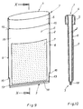
- the operating table cover 1 consists of a film tube 2 made of thermoplastic material with a closed bottom area 3 and an open head area 4 provided with a circumferential cuff edge 5.
- the operating table cover 1 is covered with an absorbent nonwoven fabric 7 and closed at its side edges 8, 9 by welds. With a steadily increasing number of operating table covers 1, the nonwovens 7 are no longer necessary due to new surgical techniques with special suction devices.
- the operating table cover 1 is pulled over a support surface 10 of an operating table 11.
- the operating table cover 1 In order to protect the surface of the nonwoven fabric 7 from possible infectious germs until shortly before its intended use, the operating table cover 1 according to FIG. 3 is pushed over the contact surface 10 in the longitudinally folded position shown there. The nurse grips on both sides with her hands under the cuff edge 5 while keeping the head area 4 open and pushes the operating table cover approximately up to its center over the support surface 10. In this position, the nonwoven fabric 7 is protected against infection germs due to its folded position. When the operating table cover 1 is pushed further over the support surface 10, the other half of the operating table cover 1 that remains folded rolls in the direction of the arrow 12 over the edge 10a until, according to FIG. 4, the operating table cover 1 is stripped over the support surface 10 except for its cuff edge 5.
- the side edges 8, 9 of the operating table cover 1 in the vicinity of the base region 3 and immediately below the cuff edge 5 are provided with inward offset regions 13, 14, the cuff edge 5 having the same width B S as that between the two offset areas 13, 14 center area 15 of the Has film tube 2.
- the length L 1 of the offset areas 14 of the side edges 8, 9 below the cuff edge 5 is slightly greater than the length L S of the cuff edge 5, while the length L 2 of the side edges 8, 9 in the vicinity of the bottom area 3 is either the same or slightly smaller or is greater than the length L S of the cuff edge 5.
- the width b 1 of the offset regions 14 below the cuff edge 5 is equal to the width b 2 of the offset regions 13 in the vicinity of the base region 3.
- the cuff edge 5 of FIGS. 7 and 8 is turned outwards in such a way that its length L S extends approximately over the length L 1 of the offset areas 14.
- the bottom region 3 can be pushed with low friction between the inside of the cuff edge 5 and the surface of the film tube 1 when folding in order to protect the nonwoven fabric 7 from infectious germs.
- the offset regions 13, 14 are designed in such a way that they can be pulled over the contact surface 10 of an operating table 11. While increased friction is to be expected at the level of these offset areas 13, 14 when covering them over the contact surface 10, this process is considerably facilitated in the central area 15 widened with its side edges 8, 9. In the prior art, this is exactly the opposite, whereby the handling of the operating table cover 1 according to the invention is also improved.
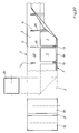
- FIGS. 11 and 12 The method according to the invention for producing an operating table cover is described below with reference to FIGS. 11 and 12, parts corresponding to FIGS. 1 to 10 being designated by the same reference numerals in FIGS. 11 to 20.
- the film tube 2 is drawn off from a supply roll 19, which in this case has already been produced from a single-layer plastic film, which is longitudinally folded exactly in its center parallel to the transport direction according to arrow 23 in the vicinity of the bottom region 3 of the later operating table covers 1. As a result, the bottom area 3 is already closed on this side, but is open on the top area 4.
- a non-woven fabric runs from a further supply roll 20, which is glued in individual blanks 7 onto the top side 6 of the film tube 2.
- this film tube 2 is formed by a film web 21 lying below in the drawing plane of FIG. 11 and a second film web 22 folded over it, as can be seen from FIGS. 13 and 18.
- the film tube 2 is underneath at the later side edges 8, 9 of the operating table cover 1 of the cuff edge 5 and in the vicinity of the base area 3 are subjected to a separating weld, as a result of which the relatively small, elongated oval waste areas 24, 25 are cut out by means of a separating weld.
- the result of the separation welding is that the two film webs 21, 22 according to FIG. 11 are tightly connected to one another at the edges 24a, 25a of the separated areas 24, 25.
- a perforation weld seam 26 extending transversely to the transport direction according to arrow 23 is attached between the two waste areas 24, 25 and at the same time the two film webs 21, 22 in the immediate vicinity of this perforation weld seam on both sides thereof 26 connected by welding and thus closed at these points.
- the film tube 2 is subjected to a first longitudinal fold, as a result of which the base region 3 comes into contact below the later cuff edge 5 and the cuts of the nonwoven fabrics 7 are folded into a protected position.
- this longitudinal fold 27 has been created, the individual blanks of the later operating table covers 1 remain both on their perforated weld seams 26 and also continuously Head area 4 connected, as can be seen from Fig. 14.
- each cuff edge 5 is provided with perforated weld seams 30 on its two side edges 5a, 5b (see FIGS. 5 and 7) and at the same time closed on both sides thereof by continuous weld seams.
- the individual cuts of the operating table covers 1 are thus connected to one another at their perforation weld seams 26 in the central region 15 and through the further perforation weld seams 30 at their cuff edges 5.
- 17 also shows the metal sheet 37 inserted to protect the areas underneath of the operating table cover 1 if the perforated weld seam 30 on the cuff edge 5 is to be created only at the height of the arrow 31.
- the method according to the invention allows the cutouts of the individual operating table covers 1, which are still connected in the production phase, to be left connected to their perforation weld seams 26, 30 in the production phase and to be wound onto a roll (not shown), from which they then serve as tear-off products for the known set -Packaging can be removed.
- FIG. 18 shows the enlarged section XVIII from FIG. 11 of two film webs 21, 22 which are still connected in the head region 4 and which are connected at the side edges 8, 9 in the central region 15 by a perforation weld seam 26.
- These operating table covers 1 are closed on their bottom area 3 by the folding edge 17 shown in FIG. 5.
- the film tube 2 is formed from two individual films 21, 22 which are congruently one above the other and drawn off by two supply rolls 19, 36 and which are connected to one another at the bottom region 3 by a continuous weld seam 18, as can be seen from FIGS .
- the operating table covers shown there are therefore formed from film tubes 2 using the method according to FIG. 20.
Landscapes
- Health & Medical Sciences (AREA)
- Life Sciences & Earth Sciences (AREA)
- Animal Behavior & Ethology (AREA)
- General Health & Medical Sciences (AREA)
- Biomedical Technology (AREA)
- Veterinary Medicine (AREA)
- Engineering & Computer Science (AREA)
- Public Health (AREA)
- Surgery (AREA)
- Medical Informatics (AREA)
- Molecular Biology (AREA)
- Heart & Thoracic Surgery (AREA)
- Wrappers (AREA)
- Absorbent Articles And Supports Therefor (AREA)
- Shaping Of Tube Ends By Bending Or Straightening (AREA)
- Making Paper Articles (AREA)
Applications Claiming Priority (2)
| Application Number | Priority Date | Filing Date | Title |
|---|---|---|---|
| DE19506046A DE19506046C1 (de) | 1995-02-22 | 1995-02-22 | Operationstischbezug sowie Verfahren zu seiner Herstellung |
| DE19506046 | 1995-02-22 |
Publications (3)
| Publication Number | Publication Date |
|---|---|
| EP0729736A2 true EP0729736A2 (fr) | 1996-09-04 |
| EP0729736A3 EP0729736A3 (fr) | 1997-07-23 |
| EP0729736B1 EP0729736B1 (fr) | 2001-05-09 |
Family
ID=7754679
Family Applications (1)
| Application Number | Title | Priority Date | Filing Date |
|---|---|---|---|
| EP96101894A Expired - Lifetime EP0729736B1 (fr) | 1995-02-22 | 1996-02-09 | Couverture pour table d'opération et procédé pour sa fabrication |
Country Status (4)
| Country | Link |
|---|---|
| US (1) | US5704370A (fr) |
| EP (1) | EP0729736B1 (fr) |
| DE (1) | DE19506046C1 (fr) |
| FI (1) | FI108703B (fr) |
Families Citing this family (7)
| Publication number | Priority date | Publication date | Assignee | Title |
|---|---|---|---|---|
| DE10102001C2 (de) | 2001-01-18 | 2003-01-30 | Hartmann Paul Ag | Gefalteter medizinischer Bezug zur Verwendung im Operationssaal und Verfahren zum Falten des Bezugs |
| US20060260622A1 (en) * | 2005-05-19 | 2006-11-23 | Wooley Deborah M | Operating room equipment drapes and methods of making and using the same |
| US7775213B2 (en) * | 2006-07-06 | 2010-08-17 | Qsum Biopsy Disposables, Llc | Medical procedure draping systems |
| US20080175879A1 (en) * | 2007-01-23 | 2008-07-24 | Feinberg Terry M | Table cloths or table covers invisible to and capable of repelling insects and animals |
| US9737363B2 (en) | 2012-08-10 | 2017-08-22 | Avent, Inc. | Sterile drape for two tiered hospital instrument table |
| US11065073B1 (en) * | 2015-12-15 | 2021-07-20 | Protection Products, Inc. | Disposable medical drape |
| US11439360B2 (en) * | 2017-08-16 | 2022-09-13 | Hologic, Inc. | Medical procedure draping system |
Family Cites Families (8)
| Publication number | Priority date | Publication date | Assignee | Title |
|---|---|---|---|---|
| US3707964A (en) * | 1970-06-20 | 1973-01-02 | Kendall & Co | Surgical drape with hand receiving cuff having internal stop guides |
| US3747655A (en) * | 1971-03-19 | 1973-07-24 | Becton Dickinson Co | Disposable mayo stand cover |
| DE3519705A1 (de) * | 1985-06-01 | 1986-12-11 | Karl-Heinz Dr. 4802 Halle Sengewald | Operationstischbezug und verfahren zu seiner herstellung |
| DE3715691A1 (de) * | 1987-05-12 | 1988-11-24 | Sengewald Klinikprodukte Gmbh | Operationstischbezug |
| DE4033243C1 (fr) * | 1990-10-19 | 1991-08-01 | Gfm Maschinenbau Gmbh, 4358 Haltern, De | |
| US5148940A (en) * | 1991-04-03 | 1992-09-22 | Microtek Medical, Inc. | Apparatus and method for disposing of infectious medical waste |
| US5411036A (en) * | 1992-11-18 | 1995-05-02 | Wilkes; Kenneth R. | Mayo stand cover |
| US5433221A (en) * | 1994-10-05 | 1995-07-18 | Adair; Edwin L. | Windowed self-centering drape for surgical camera |
-
1995
- 1995-02-22 DE DE19506046A patent/DE19506046C1/de not_active Expired - Fee Related
-
1996
- 1996-02-09 EP EP96101894A patent/EP0729736B1/fr not_active Expired - Lifetime
- 1996-02-21 FI FI960782A patent/FI108703B/fi not_active IP Right Cessation
- 1996-02-22 US US08/604,223 patent/US5704370A/en not_active Expired - Fee Related
Also Published As
| Publication number | Publication date |
|---|---|
| EP0729736A3 (fr) | 1997-07-23 |
| FI108703B (fi) | 2002-03-15 |
| DE19506046C1 (de) | 1996-01-11 |
| FI960782A0 (fi) | 1996-02-21 |
| FI960782A7 (fi) | 1996-08-23 |
| EP0729736B1 (fr) | 2001-05-09 |
| US5704370A (en) | 1998-01-06 |
Similar Documents
| Publication | Publication Date | Title |
|---|---|---|
| DE3319754C2 (fr) | ||
| EP0574449B1 (fr) | Sachet tubulaire d'emballage, notamment de marchandises du type serviettes hygieniques | |
| EP0544156B1 (fr) | Emballage pour feuilles en papier, en particulier pour mouchoirs en papier | |
| EP0162291A1 (fr) | Emballage pour marchandises en colis | |
| WO1992016431A1 (fr) | Emballage en forme de sachet tubulaire | |
| DE69003795T2 (de) | Tragetasche aus Kunststoffolie. | |
| DE60003781T2 (de) | Stapel mit sich überlappenden ineinandergefaltenen laminaren Artikeln, Verpackung dafür und Verfahren zur dessen Herstellung | |
| EP0729736B1 (fr) | Couverture pour table d'opération et procédé pour sa fabrication | |
| DE2623404C3 (de) | Quaderförmige, leicht zu öffnende Packung, die aus flexiblem bzw. biegbarem schlauchförmigen Verpackungsmaterial gebildet ist | |
| EP0944524B1 (fr) | Fabrication d'un tuyau plastique en continu | |
| EP0399540B1 (fr) | Procédé et dispositif pour envelopper des marchandises avec une housse de film étirable et ensemble d'emballage formé avec ceux-ci | |
| EP0450114B1 (fr) | Procédé pour la fabrication d'une pochette d'emballage portable en plastique avec la partie haute pliée | |
| DE3008807C2 (fr) | ||
| DE102007026807A1 (de) | Beutel zur Aufnahme von Lebensmitteln, enthaltend eine Perforationsnaht | |
| EP0974532A2 (fr) | Distributeur pour bloc de sachets en film de matière thermoplastique | |
| WO2016165686A1 (fr) | Emballage de matériaux en rouleaux | |
| DE2547049C2 (de) | Wickelbeutel aus miteinander verbundenen thermoplastischen Kunststoffolien und Vorrichtung zum Anbringen eines Verschlußstreifens in der Öffnung der Tasche eines derartigen Wickelbeutels | |
| WO2012106742A1 (fr) | Procédé de fermeture d'un corps de sac tubulaire | |
| DE10127278A1 (de) | Hygieneprodukt sowie Verfahren und Vorrichtung zu seiner Herstellung | |
| DE2627558A1 (de) | Zu einer rolle aufgewickelte hygienepapier-bahn | |
| DE2724999B2 (de) | Wegwerfbare Kochhaube | |
| DE9017942U1 (de) | Beutelstrang und davon abgetrennter Beutel | |
| DE2928105C2 (de) | Verpackung für Flüssigkeiten mit Ausgießvorrichtung | |
| DE4033243C1 (fr) | ||
| DE19956846A1 (de) | Packungseinheit |
Legal Events
| Date | Code | Title | Description |
|---|---|---|---|
| PUAI | Public reference made under article 153(3) epc to a published international application that has entered the european phase |
Free format text: ORIGINAL CODE: 0009012 |
|
| AK | Designated contracting states |
Kind code of ref document: A2 Designated state(s): FR GB IT NL |
|
| PUAL | Search report despatched |
Free format text: ORIGINAL CODE: 0009013 |
|
| AK | Designated contracting states |
Kind code of ref document: A3 Designated state(s): FR GB IT NL |
|
| 17P | Request for examination filed |
Effective date: 19970912 |
|
| GRAG | Despatch of communication of intention to grant |
Free format text: ORIGINAL CODE: EPIDOS AGRA |
|
| 17Q | First examination report despatched |
Effective date: 20000406 |
|
| GRAG | Despatch of communication of intention to grant |
Free format text: ORIGINAL CODE: EPIDOS AGRA |
|
| GRAG | Despatch of communication of intention to grant |
Free format text: ORIGINAL CODE: EPIDOS AGRA |
|
| GRAH | Despatch of communication of intention to grant a patent |
Free format text: ORIGINAL CODE: EPIDOS IGRA |
|
| GRAH | Despatch of communication of intention to grant a patent |
Free format text: ORIGINAL CODE: EPIDOS IGRA |
|
| RAP1 | Party data changed (applicant data changed or rights of an application transferred) |
Owner name: GFM MASCHINENBAU GMBH |
|
| GRAA | (expected) grant |
Free format text: ORIGINAL CODE: 0009210 |
|
| AK | Designated contracting states |
Kind code of ref document: B1 Designated state(s): FR GB IT NL |
|
| ITF | It: translation for a ep patent filed | ||
| GBT | Gb: translation of ep patent filed (gb section 77(6)(a)/1977) |
Effective date: 20010802 |
|
| ET | Fr: translation filed | ||
| REG | Reference to a national code |
Ref country code: GB Ref legal event code: IF02 |
|
| PLBE | No opposition filed within time limit |
Free format text: ORIGINAL CODE: 0009261 |
|
| STAA | Information on the status of an ep patent application or granted ep patent |
Free format text: STATUS: NO OPPOSITION FILED WITHIN TIME LIMIT |
|
| 26N | No opposition filed | ||
| PGFP | Annual fee paid to national office [announced via postgrant information from national office to epo] |
Ref country code: FR Payment date: 20040202 Year of fee payment: 9 |
|
| PGFP | Annual fee paid to national office [announced via postgrant information from national office to epo] |
Ref country code: NL Payment date: 20040216 Year of fee payment: 9 |
|
| PG25 | Lapsed in a contracting state [announced via postgrant information from national office to epo] |
Ref country code: IT Free format text: LAPSE BECAUSE OF NON-PAYMENT OF DUE FEES Effective date: 20050209 |
|
| PGFP | Annual fee paid to national office [announced via postgrant information from national office to epo] |
Ref country code: GB Payment date: 20050209 Year of fee payment: 10 |
|
| PG25 | Lapsed in a contracting state [announced via postgrant information from national office to epo] |
Ref country code: NL Free format text: LAPSE BECAUSE OF NON-PAYMENT OF DUE FEES Effective date: 20050901 |
|
| PG25 | Lapsed in a contracting state [announced via postgrant information from national office to epo] |
Ref country code: FR Free format text: LAPSE BECAUSE OF NON-PAYMENT OF DUE FEES Effective date: 20051031 |
|
| NLV4 | Nl: lapsed or anulled due to non-payment of the annual fee |
Effective date: 20050901 |
|
| REG | Reference to a national code |
Ref country code: FR Ref legal event code: ST Effective date: 20051031 |
|
| PG25 | Lapsed in a contracting state [announced via postgrant information from national office to epo] |
Ref country code: GB Free format text: LAPSE BECAUSE OF NON-PAYMENT OF DUE FEES Effective date: 20060209 |
|
| GBPC | Gb: european patent ceased through non-payment of renewal fee |
Effective date: 20060209 |